Table of Contents
Advertisement
Quick Links
Advertisement
Table of Contents

Subscribe to Our Youtube Channel
Related Manuals for Conel CDA 70

Summary of Contents for Conel CDA 70
- Page 1 WWW.INFOPULSAS.LT info@infopulsas.lt Declared system ISO 9001:2009...
-
Page 2: Table Of Contents
CONTENTS Contents Safety instructions Description of the CDA70 radio modem 2.1. General 2.2. Examples of possible applications 2.3. Description of individual components 2.3.1. Radio component 2.3.2. Modem component 2.3.3. Microcomputer 2.3.4. Inputs and outputs for telemetry 2.3.5. User interface protocols 2.3.6. - Page 3 Attention – notice on possible problems, which can arise to in specific cases. Information, notice – information, which contains useful advices or special interest. Conel s.r.o., Sokolska 71, 562 04 Usti nad Orlici, Czech Republic Issue in CZ, 8/11/2010...
-
Page 4: Safety Instructions
• Use only the original Conel company accessories. Thus you will prevent possible health risks and damage to the devices and ensure compliance with all relevant provisions. Unauthorised adjustments or use of unapproved accessories may result in damage to the module and breach of applicable laws. -
Page 5: Description Of The Cda70 Radio Modem
CDA70 MODEM DESCRIPTION 2. Description of the CDA70 radio modem 2.1. General The CDA70 radio modem is a device for wireless data transmission. Communication between two radio modems is a simplex one and is carried out on a single frequency. Modems work in frequency band of 143 to 174 MHz (CDA70V) and 403 to 470 MHz (CDA70U). -
Page 6: Modem Component
CDA70 MODEM DESCRIPTION Modem component 2.3.2. The modem part converts digital bit flow from the microcomputer to the FFSK or GMSK analogue modulation, which is brought to the transmitter of the radio data module. And vice versa, it converts analogue signal from the receiver to digital bit flow to the microcomputer. The modem part is designed on the basis of a CML integrated circuit. -
Page 7: User Interface Protocols
CDA70 MODEM DESCRIPTION outputs. With the equipment you may establish simple telemetry at low cost, without the use of industrial control automat. User interface protocols 2.3.5. For user interface, a range of standard protocols is implemented: • AT modem • PROFIBUS •... -
Page 8: Technical Parameters
CDA70 MODEM DESCRIPTION Technical parameters 2.3.6. Frequency band 143 – 174 MHz (CDA70V version) 403 – 470 MHz (CDA70U version) Adjustment of working frequency program setting Adjustment of working frequency of separate for each part receiver and transmitter Adjustment of channel spacing program setting 12,5;... -
Page 9: Radio Modem Status Indication
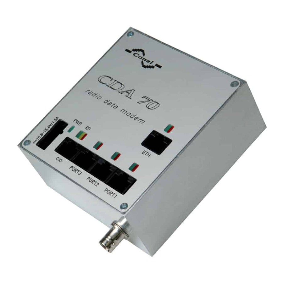
CDA70 MODEM DESCRIPTION 2.4. Radio modem status indication Seven LED status indicators informing of the radio data modem status are located on the front panel. They are arranged in three arrays: Colour Group Meaning Blinking 1:9…..……..proper function Blinking 9:1…..……..RF monitoring Permanently on .. -
Page 10: Connection Of Port1, Port2 And Port3 Connectors (Rs232)
CDA70 MODEM DESCRIPTION Connection of PORT1, PORT2 and PORT3 connectors (RS232) 2.5.1. (RS232 – DCE – Data Communication Equipment) Signal Description Data flow direction number mark Request To Send Input Clear To Send Output Data Terminal Ready Input Data Set Ready - connected to +12V through Output 1k8 Ohm resistor GROUND - signal ground... -
Page 11: Connection Of Port1 Connectors (M-Bus)
CDA70 MODEM DESCRIPTION modem CDA70 Circuit example of the RS232 equipment with Cable KD-2 Modem CDA70 PORT3 PORT2 PORT1 Connection of PORT1 connectors (M-BUS) 2.5.2. Panel socket RJ45 Signal Description Data flow direction number mark SGND Signal and supply ground SGND Signal and supply ground TxRx-... -
Page 12: Connection Of Port2 Connectors (Rs485G)
MBUS (-) Meter MBUS (+) M-BUS data cable more than 10 m it is need to use over-voltage protection on CDA 70 modem side! External or internal power supply of expansion port M-BUS it is can evoke by wiring of the jumper. For details see chapter 2.8. - Page 13 RS485 (+) At RS485 data cable more than 10 m it is need to use over-voltage protection on CDA 70 modem side! External or internal power supply of expansion port RS485 it is can evoke by wiring of the jumpers. For details see chapter 2.8.
-
Page 14: Connection Of Eth Connectors (Ethernet)
CDA70 MODEM DESCRIPTION Connection of ETH connectors (ETHERNET) 2.5.4. Panel socket RJ45 Data flow Signal mark Description number direction TXD+ Transmit Data Input/Output TXD- Transmit Data Input/Output RXD+ Receive Data Input/Output RXD- Receive Data Input/Output ATTENTION! Port ETH is not with POE (Power Over Ethernet) compatible! to equipment with Ethernet Circuit example of the CDA70 with UTP cable... - Page 15 CDA70 MODEM DESCRIPTION...
-
Page 16: Power Supply Connector (Pwdd)
CDA70 MODEM DESCRIPTION Power supply connector (PWDD) 2.5.6. Signal mark Description number +12V Positive pole of supply voltage Negative pole of supply voltage PWRSV Open collector output (Power Save) for controlling of supply voltage of the whole radio modem, see chapter 3.4 Input -power failure supervision. - Page 17 CDA70 MODEM DESCRIPTION Circuit example: DC supply Pin 1 – +12V Pin 2 – GND Modem CDA70 Pin 3 – PWRSV Pin 4 – INAC DC supply with backup battery with present supply monitoring Pin 1 – +12V Pin 2 – GND Modem CDA70 Pin 3 –...
-
Page 18: Antenna Connection
CDA70 MODEM DESCRIPTION 2.6. Antenna connection Antenna is connected to the radio data modem via a BNC connector located on the side panel. 2.7. Power supply Supply voltage working range of the radio modem is +10.8 to +15.6V dc (12V accumulator). -
Page 19: Ports Technical Specifications
CDA70 MODEM DESCRIPTION 2.8. Ports technical specifications • RS232 Name of product RS232 Power supply Internal ..Environment Operating temperature -20 .. +55 C Storage temperature -20 .. +85 C Standards Emission EN 55022/B Immunity ETS 300 342 Safety EN 60950 RS232 specifications Max. - Page 20 CDA70 MODEM DESCRIPTION Connection of the jumpers: CDA-70-U(V)-EM version CDA-70-U(V)-4M version Jumpers SK7 and SK8 Jumper J3 • M-BUS Name of port M-BUS Power supply Voltage 10,8 .. 15,6 V Supply power Max. 30 W Environment Operating temperature -20 .. +55 C Storage temperature -20 ..
- Page 21 CDA70 MODEM DESCRIPTION Connection of the jumpers: CDA-70-U(V)-EM version CDA-70-U(V)-4M version Jumpers SK9 a SK10 Jumper J4 • Ethernet Port Power supply Internal Environment Operating temperature -20 .. +55 C Storage temperature -20 .. +85 C Standards Emission EN 55022/B Immunity ETS 300 342 Safety...
-
Page 22: Configuration Of Radio Modem
CDA70 - PC connection cable with DCR and GND signals connected at 100 Ohm. It is made from normal data cable by adding service interconnection. It is necessary to interconnect all eight signals between CDA 70 and PC. See description of the RJ45 connector in chapter 2.5.1. -
Page 23: Accessories
CDA70 MODEM DESCRIPTION 2.11. Accessories 1. Power supply connector for a power supply cable 2. Three RJ45 connectors to complete the data cable by snapping to the cable. 3. Compliance certificate 4. Complaint procedure 5. Warranty 2.12. Additional accessories 1. CIO-ReO-2 – expansion module with relay output 2. -
Page 24: Mechanical Drawing Of Cda70 And Recommendations For Montage
CDA70 MODEM DESCRIPTION 2.13. Mechanical drawing of CDA70 and recommendations for montage For the majority of applications with a built-in modem in a switch board it is possible to recognize two sorts of environments: • nonpublic and industry environment of low voltage with high interference, •... - Page 25 CDA70 MODEM DESCRIPTION For compliance of EN 60439 - 1 + A1 specification it is necessary observe next assembly of the modem to the switch - board: • round antenna we recommend to observe a distance of 6 cm from cables and metal surfaces on every side according to the next picture due to the elimination of interference, while using an external antenna except for the switch-board it is necessary to fit a lightening conductor,...
- Page 26 CDA70 MODEM DESCRIPTION • sufficient space must be left before individual connectors for handling of cables, • for correct function of the modem we recommend to use in switch - board earth- bonding distribution frame for grounding of power supply of modem, data cables and antenna, •...
-
Page 27: Product Marking
CDA70 MODEM DESCRIPTION 2.14. Product marking Antenna Marking Power supply Other connector CDA-70-XX-YY +10,8 to 15,6 V DC XX – frequency band U 403 to 470 MHz 143 to 174 MHz YY – port 3x RS232 configuration 1x M-BUS + 1x RS485 + 1x RS232 1x Ethernet + 3 x RS232 1x Ethernet + 1x M-BUS + 1x RS485 + 1x RS232 1x CAN... -
Page 28: Assembly Procedure
CDA70 MODEM DESCRIPTION 2.15. Assembly procedure The radio data modem CDA70 is designed as a standard for: 1. DIN 35 mm rail assembly using plastic grips. - Page 29 CDA70 MODEM DESCRIPTION 2. DIN 35 mm rail assembly using plastic grips from back side.
-
Page 30: Product Label
CDA70 MODEM DESCRIPTION 2.16. Product label... -
Page 31: Basic Parameters Description
[1]. In right under main menu is function list where is possible choice Configuration (Ctrl + F1). Next table describes parameters of the tap Basic. Ports description is depend on used protocol. Protocols description is possible to get from Conel Company. Set value... - Page 32 CDA70 MODEM DESCRIPTION Set value Parameter name Parameter description range RF channel protocol Information about used radio channel protocol. Relay station YES/NO Indicates relay property of this station. Only for automatic tables. Mobile station YES/NO When this parameter is set on YES, than this modem never works as relay station and sends data directly to destination stations (no relay) regardless of signal levels.
- Page 33 CDA70 MODEM DESCRIPTION Set value Parameter name Parameter description range Low threshold RF -90 up to -130 Threshold of RF signal level when the RF signal level channel is considered to be busy. Maximum number of 1 up to 10 Maximum number of packets which are linked packets linked together and send at once.
- Page 34 CDA70 MODEM DESCRIPTION Set value Parameter name Parameter description range Log CIO YES/NO When this parameter is set to YES, than CIO information is stored to the journal. Log service events YES/NO When this parameter is set to YES, than service events are stored to the journal.
-
Page 35: Cio - Analogue Inputs And Binary Outputs
CIO DESCRIPTION 3. CIO - analogue inputs and binary outputs 3.1. Introduction CDA70 is equipped with a user interface (I/O) for scanning and processing of analogue signals and for controlling (setting) of binary signals. The user can use five adjustable inputs outputs, which are placed on the I/O connector at the back panel of the module. -
Page 36: I/O Signals Parameters
CIO DESCRIPTION I/O signals parameters 3.2.4. Signal Measuring Resolution Sampling Average Hysteresis Control level name range [V] [bit] [msec] from samples I/O1-5 0 to 5 Optional Optional Optional 1 - 128 0 - 255 3.3. Measuring other CDA70 signals Measuring the supply voltage 3.3.1. -
Page 37: Measuring Dsr Output Signal Level
CIO DESCRIPTION Measuring DSR output signal level 3.3.3. On CDA70 side, DSR signals on individual user interfaces are output signals. They are not internally controlled. Individual signals are connected via 1k8 ohms resistors to the 12V supply voltage (the same voltage as at the supply connector of CDA70). Due to the loading of DSR output by a 100 ohm resistor to the earth, the supply voltage on the output drops to 2V. - Page 38 CIO DESCRIPTION LED on the front panel. Input circuits are protected against short-time over voltage by suppressors and against the long-time one by a reverse fuse. Ranges of the measured values: U 1V, U 2V, U 5V, U 10V, U 20V I 5mA, I 10mA, I 20mA Pt100 100 C, Pt100 200...
-
Page 39: Reference
[2] Conel s.r.o.: Application CGU Server, 2004 [3] Conel s.r.o.: CIO 2 User’s guide, 2008 5. Links to related products of the manufacturer For related and referenced products and material, see the Conel website: www.conel.cz 5.1. Systems AGNES - a comprehensive communication system made by Conel. -
Page 40: Complaints Procedure
COMPLAINTS PROCEDURE 7. Complaints procedure Dear customer, The product you have purchased had passed manufacturer's tests and its functions had been checked by our technician before sale. In case any defect shows up during the guarantee period that prevents normal use we ask you to follow the Complaints procedure when registering your claim. - Page 41 COMPLAINTS PROCEDURE The claim is deemed unsubstantiated when the defect is not found by the vendor processing the complaint or the defect is not covered by the guarantee under Article 3 of the procedure. In case the claimed defect is not found and functionality is proven to the customer, the customer is obliged to pay demonstrable cost related to expert assessment of the claimed defect.
-
Page 42: Warranty
WARRANTY 8. Warranty Device type Serial number Guarantee period (months) Vendor Date of purchase Seal of the vendor... - Page 43 WARRANTY Date of complaint registration Complaint protocol number Date of reception of the device in repair shop Date of finished repair Number of repair sheet Warranty repair YES - NO YES - NO YES - NO YES - NO YES - NO New serial number of the device...
Need help?
Do you have a question about the CDA 70 and is the answer not in the manual?
Questions and answers