Table of Contents
Advertisement
Quick Links
Advertisement
Chapters
Table of Contents

Related Manuals for FujiFilm ALPHA 5 RYT-SX

Summary of Contents for FujiFilm ALPHA 5 RYT-SX
- Page 1 FUJI SERVO SYSTEM USER'S MANUAL RYT-SX type MEHT301a...
- Page 2 This manual is "User's Manual for Fuji AC Servo System ALPHA5 Series". The user's manual is in one volume and covers all handling methods of the product. The following documents are included in the package of each device. Device Document name Doc.
- Page 3 CHAPTER 0 INTRODUCTION CHAPTER 1 INSTALLATION CHAPTER 2 WIRING CHAPTER 3 OPERATION CHAPTER 4 PARAMETER CHAPTER 5 SERVO ADJUSTMENT CHAPTER 6 KEYPAD CHAPTER 7 MAINTENANCE AND INSPECTION CHAPTER 8 SPECIFICATIONS CHAPTER 9 CHARACTERISTICS CHAPTER 10 PERIPHERAL EQUIPMENT CHAPTER 11 ABSOLUTE POSITION SYSTEM CHAPTER 12 POSITIONING DATA CHAPTER 13 PC LOADER CHAPTER 14 APPENDIXES...
-
Page 4: Table Of Contents
Contents CHAPTER 0 INTRODUCTION Safety Precautions ・・・・・・・・・・・・・・・・・・・・・・・・・・・・・・・・・・・・・・・・・・ ■ Precautions on use ・・・・・・・・・・・・・・・・・・・・・・・・・・・・・・・・・・・・・・・・・・・・・・・・・・・・・・・ ■ Precautions on storage ・・・・・・・・・・・・・・・・・・・・・・・・・・・・・・・・・・・・・・・・・・・・・・・・・・・ ■ Precautions on transportation ・・・・・・・・・・・・・・・・・・・・・・・・・・・・・・・・・・・・・・・・・・・・・・ ■ Precautions on installation ・・・・・・・・・・・・・・・・・・・・・・・・・・・・・・・・・・・・・・・・・・・・・・・・ ■ Precautions on wiring ・・・・・・・・・・・・・・・・・・・・・・・・・・・・・・・・・・・・・・・・・・・・・・・・・・・・・ ■ Precautions on operation ・・・・・・・・・・・・・・・・・・・・・・・・・・・・・・・・・・・・・・・・・・・・・・・・・ ■ General precautions ・・・・・・・・・・・・・・・・・・・・・・・・・・・・・・・・・・・・・・・・・・・・・・・・・・・・・・... - Page 5 1.2.2 Operating Environment ・・・・・・・・・・・・・・・・・・・・・・・・・・・・・・・・・・・・ 1.2.3 Installing the Servo Amplifier ・・・・・・・・・・・・・・・・・・・・・・・・・・・・・・・ 1.2.4 Depth of Control Panel ・・・・・・・・・・・・・・・・・・・・・・・・・・・・・・・・・・・・ 1-10 CHAPTER 2 WIRING Configuration ・・・・・・・・・・・・・・・・・・・・・・・・・・・・・・・・・・・・・・・・・・・・・・・ 2.1.1 Part Name ・・・・・・・・・・・・・・・・・・・・・・・・・・・・・・・・・・・・・・・・・・・・・・・ 2.1.2 Configuration ・・・・・・・・・・・・・・・・・・・・・・・・・・・・・・・・・・・・・・・・・・・・・ 2.1.3 Sequence I/O ・・・・・・・・・・・・・・・・・・・・・・・・・・・・・・・・・・・・・・・・・・・・ 2-12 2.1.3.1 Pulse Input (PPI, CA, *CA, CB, *CA) ・・・・・・・・・・・・・・・・・・・・・・・・・・・・・・・・・...
- Page 6 Interrupt input: Sequence input signal (Reference value 49) ・・・・・・・・・・・・・・・・・・・ 2-38 Over-travel in positive direction [+OT]: Sequence input signal (Reference value 7) ・・・・・・・・・・・・・・・・・・・・・・・・・・・・・・・・・・・・・・・・・・・・・・・・・・・・・・ 2-40 Over-travel in negative direction [-OT]: Sequence input signal (Reference value 8) ・・・・・・・・・・・・・・・・・・・・・・・・・・・・・・・・・・・・・・・・・・・・・・・・・・・・・・ 2-40 ABS/INC: Sequence input signal (Reference value 9) ・・・・・・・・・・・・・・・・・・・・・・・・...
- Page 7 Free-run [BX]: Sequence input signal (Reference value 54) ・・・・・・・・・・・・・・・・・・・ 2-61 Edit permission: Sequence input signal (Reference value 55) ・・・・・・・・・・・・・・・・・・ 2-62 Anti resonance frequency selection 0: Sequence input signal (Reference value 57) 2-63 ・・・・・・・・・・・・・・・・・・・・・・・・・・・・・・・・・・・・・・・・・・・・・・・・・・・・ Anti resonance frequency selection 1: Sequence input signal (Reference value 58) ・・・・・・・・・・・・・・・・・・・・・・・・・・・・・・・・・・・・・・・・・・・・・・・・・・・・...
- Page 8 Speed coincidence [NARV]: Sequence output signal (Reference value 25) ・・・・・・ 2-81 Torque limit detection: Sequence output signal (Reference value 26) ・・・・・・・・・・・ 2-82 Overload warning detection: Sequence output signal (Reference value 27) ・・・・・・ 2-82 Servo control ready [S-RDY]: Sequence output signal (Reference value 28) 2-84 ・・・・・...
- Page 9 CONTa Through: Sequence output signal (Reference value 91) ・・・・・・・・・・・・・・・ 2-96 CONTb Through: Sequence output signal (Reference value 92) ・・・・・・・・・・・・・・・ 2-96 CONT1 Through: Sequence output signal (Reference value -) ・・・・・・・・・・・・・・・・・ 2-96 CONT2 Through: Sequence output signal (Reference value -) 2-96 ・・・・・・・・・・・・・・・・・ CONT3 Through: Sequence output signal (Reference value -) ・・・・・・・・・・・・・・・・・...
- Page 10 3.4.3 Positioning Data Operation ・・・・・・・・・・・・・・・・・・・・・・・・・・・・・・・・ 3-35 3.4.4 Pulse Operation ・・・・・・・・・・・・・・・・・・・・・・・・・・・・・・・・・・・・・・・・・ 3-37 3.4.5 Interrupting/Stopping Operation ・・・・・・・・・・・・・・・・・・・・・・・・・・・・ 3-38 3.4.6 Reading/writing a Parameter 3-46 ・・・・・・・・・・・・・・・・・・・・・・・・・・・・・・ 3.4.7 Reading/writing a Positioning Data ・・・・・・・・・・・・・・・・・・・・・・・・・ 3-49 3.4.8 Selecting the Monitor ・・・・・・・・・・・・・・・・・・・・・・・・・・・・・・・・・・・・・ 3-53 CHAPTER 4 PARAMETER Parameter Division ・・・・・・・・・・・・・・・・・・・・・・・・・・・・・・・・・・・・・・・・・・...
- Page 11 PA1_36 to 40 Acceleration / deceleration selection at speed control, Acceleration time and deceleration time settings ・・・・・・・・・・・・・・・ 4-19 PA1_41 to 47 Manual feed speed 1 to 7 ・・・・・・・・・・・・・・・・・・・・・・・・・・・・・・・・・・ 4-21 ・・・・・・・・・・・・・・・・・・ Control Gain and Filter Setting Parameters 4-22 4.3.1 List (PA1_ ・・・・・・・・・・・・・・・・・・・・・・・・・・・・・・・・・・・・・・・・・・...
- Page 12 PA2_13 Home position LS signal edge selection ・・・・・・・・・・・・・・・・・・・・・・・・・・・ 4-40 PA2_14 Home position shift unit amount ・・・・・・・・・・・・・・・・・・・・・・・・・・・・・・・・・・ 4-41 PA2_15 Deceleration operation for creep speed ・・・・・・・・・・・・・・・・・・・・・・・・・・・・ 4-41 PA2_16 Home position after homing completion 4-42 ・・・・・・・・・・・・・・・・・・・・・・・・・・・ PA2_17 Home position detection range ・・・・・・・・・・・・・・・・・・・・・・・・・・・・・・・・・・・ 4-42 PA2_18 Deceleration time at OT during homing ・・・・・・・・・・・・・・・・・・・・・・・・・・・・...
- Page 13 PA2_78 Display transition at warning detection ・・・・・・・・・・・・・・・・・・・・・・・・・・・・ 4-81 PA2_80 to 85 Parameter in RAM 1 to 6 ・・・・・・・・・・・・・・・・・・・・・・・・・・・・・・・・・・・ 4-82 PA2_86 to 88 Positioning data in RAM 1 to 3 ・・・・・・・・・・・・・・・・・・・・・・・・・・・・・・ 4-82 PA2_89 and 90 Sequence test mode: Mode selection and encoder selection 4-83 ・・・...
- Page 14 5.5.4 Manual Tuning Adjustment Procedure ・・・・・・・・・・・・・・・・・・・・・・ 5-17 5.5.5 Individual Adjustment ・・・・・・・・・・・・・・・・・・・・・・・・・・・・・・・・・・・・・ 5-18 ・・・・・・・・・・・・・・・・・・・・・・・・・・・・・・・・ Interpolation Control Mode 5-19 5.6.1 Conditions for Interpolation Control Mode 5-19 ・・・・・・・・・・・・・・・・・・・ 5.6.2 Parameters Used for Interpolation Control Mode ・・・・・・・・・・・・・ 5-19 5.6.3 Adjustment Procedure in Interpolation Control Mode ・・・・・・・・・・...
- Page 15 7.5.3 Discarding ・・・・・・・・・・・・・・・・・・・・・・・・・・・・・・・・・・・・・・・・・・・・・・ 7-17 Approximate Replacement Timing ・・・・・・・・・・・・・・・・・・・・・・・・・・ 7-18 CHAPTER 8 SPECIFICATIONS Specifications of Servomotor ・・・・・・・・・・・・・・・・・・・・・・・・・・・・・・・・ 8.1.1 GYS Motor ・・・・・・・・・・・・・・・・・・・・・・・・・・・・・・・・・・・・・・・・・・・・・・・ 8.1.2 GYC Motor ・・・・・・・・・・・・・・・・・・・・・・・・・・・・・・・・・・・・・・・・・・・・・・・ 8.1.3 GYG Motor [2000 r/min] 8-10 ・・・・・・・・・・・・・・・・・・・・・・・・・・・・・・・・・・・ 8.1.4 GYG Motor [1500 r/min] ・・・・・・・・・・・・・・・・・・・・・・・・・・・・・・・・・・・ 8-12 Specifications of Servo Amplifier ・・・・・・・・・・・・・・・・・・・・・・・・・・・...
- Page 16 CHAPTER 10 PERIPHERAL EQUIPMENT 10-1 10.1 Overall Configuration of Peripheral Equipment ・・・・・・・・・・・・・・ 10-2 ・・・・・・・・・・・・・・・・・・・・・・・・・・・・・・・・・・・・・・・・・・・・・・・・ 10.2 Cable Size 10-3 10.2.1 Main Circuit Section Cable Size 10-4 ・・・・・・・・・・・・・・・・・・・・・・・・・・・・ 10.2.2 Encoder Cable 10-6 ・・・・・・・・・・・・・・・・・・・・・・・・・・・・・・・・・・・・・・・・・・・ 10.2.3 How to Calculate the Servo Amplifier Input Current ・・・・・・・・・・・...
- Page 17 Monitor (CN6) ・・・・・・・・・・・・・・・・・・・・・・・・・・・・・・・・・・・・・・・・・・・・・・・・・・・・・・・・・・ 10-34 External braking resistor (1) ・・・・・・・・・・・・・・・・・・・・・・・・・・・・・・・・・・・・・・・・・・・・・・ 10-34 External braking resistor (2) ・・・・・・・・・・・・・・・・・・・・・・・・・・・・・・・・・・・・・・・・・・・・・・ 10-35 External braking resistor (3) 10-36 ・・・・・・・・・・・・・・・・・・・・・・・・・・・・・・・・・・・・・・・・・・・・・・ External braking resistor (4) ・・・・・・・・・・・・・・・・・・・・・・・・・・・・・・・・・・・・・・・・・・・・・・ 10-37 External braking resistor (5) ・・・・・・・・・・・・・・・・・・・・・・・・・・・・・・・・・・・・・・・・・・・・・・ 10-38 CHAPTER 11 ABSOLUTE POSITION SYSTEM 11-1 11.1 Specifications ・・・・・・・・・・・・・・・・・・・・・・・・・・・・・・・・・・・・・・・・・・・・...
- Page 18 CHAPTER 13 PC LOADER 13-1 13.1 Operating Environment ・・・・・・・・・・・・・・・・・・・・・・・・・・・・・・・・・・・・ 13-2 ・・・・・・・・・・・・・・・・・・・・・・・・・・・・・・・・・・・・・・・・ 13.2 Installation Method 13-2 ・・・・・・・・・・・・・・・・・・・・・・・・・・・・・・・・・・・・・・・・・・・・・ 13.3 Function List 13-9 ・・・・・・・・・・・・・・・・・・・・・・・・・・・・・・・・・ 13.4 Use Method at Setting Up 13-10 13.5 Detail Description of Function ・・・・・・・・・・・・・・・・・・・・・・・・・・・・・ 13-11 13.5.1 Real-Time Trace ・・・・・・・・・・・・・・・・・・・・・・・・・・・・・・・・・・・・・・・・ 13-11 13.5.2 Historical Trace ・・・・・・・・・・・・・・・・・・・・・・・・・・・・・・・・・・・・・・・・・...
-
Page 19: Chapter 0 Introduction
CHAPTER 0 INTRODUCTION... -
Page 20: Safety Precautions
CHAPTER 0 INTRODUCTION 0.1 Safety Precautions (1) Types and meanings of warning signs Before starting installation, wiring work, maintenance or inspection, read through this manual and other attached documents. Be familiar with the device, safety information and precautions before using. In this manual, safety precautions are described in two categories: "WARNING"... -
Page 21: Precautions On Use
CHAPTER 0 INTRODUCTION ■ Precautions on use WARNING Do not touch the inside of the servo amplifier. There is a risk of electric shock. Make sure to ground the grounding terminal of the servo amplifier and servomotor. There is a risk of electric shock. Before performing wiring or inspection, turn the power off and wait for at least five minutes, and check that the charge LED is unlit. -
Page 22: Precautions On Storage
CHAPTER 0 INTRODUCTION ■ Precautions on storage CAUTION Do not store at places susceptible to rain or water splashes or toxic gases or liquid. It might cause failure. Store at places without direct sunshine within the predetermined temperature and humidity range (between -20 [°C] and 60 [°C], between 10 [%] and 90 [%] RH, without condensation). -
Page 23: Precautions On Installation
CHAPTER 0 INTRODUCTION ■ Precautions on installation CAUTION Do not ride on the servomotor or place a heavy matter on it. It might cause failure, breakage, electric shock and injuries. Do not block the exhaust port or do not allow foreign substance to enter. It might cause fire and electric shock. -
Page 24: Precautions On Wiring
CHAPTER 0 INTRODUCTION ■ Precautions on wiring CAUTION Never apply the commercial power supply to the U, V and W terminals of the servomotor. It might cause fire and failure. Do not connect the grounding (E) cable to the U, V and W terminals of the servomotor. Do not connect the U, V and W terminals in inappropriate order. -
Page 25: Precautions On Operation
CHAPTER 0 INTRODUCTION ■ Precautions on operation CAUTION In order to avoid unstable motions, never change adjustment radically. It might cause injuries. To perform test operation, fix the servomotor and leave it disconnected from the mechanical system. After checking the motion, connect to the machine. Otherwise, it might cause injuries. -
Page 26: General Precautions
CHAPTER 0 INTRODUCTION ■ General precautions CAUTION Drawings in this manual may show the state without covers or shields for safety to explain in details. Restore the covers and shields in the original state when operating the product. In case of disposal of the product, comply with the following two laws and act in accordance with each regulation. -
Page 27: Compliance With Eu Directives
CHAPTER 0 INTRODUCTION ■ Compliance with EU directives EU directives aim at integration of regulations among the EU member countries to promote distribution of safety assured products. It is required to satisfy basic safety requirements including machine directive (enacted in January 1995), EMC directive (enacted in January 1996), and low voltage directive (enacted in January 1997) and affix a CE mark (CE marking) on the product sold in EU member countries. -
Page 28: Compliance With Eu Directives And Ul/Csa Standard
CHAPTER 0 INTRODUCTION ■ Compliance with EU Directives and UL/CSA Standard • Safety Standard for North America (UL) UL standard (UL File No.) Servo amplifier UL508C (E132902) Servomotor UL1004 (E102475) • EC Directives Low voltage EMC directive directive Servo amplifier EN50178 EN55011 EN61800-3... -
Page 29: Outline Of System
CHAPTER 0 INTRODUCTION 0.2 Outline of System ALPHA 5 Series is an AC servo system that supports various host interfaces and realizes the best motion control for the target machine. 0.2.1 Servomotor The variation of the servomotor includes three types: slim type (GYS), cubic type (GYC) and medium inertia type (GYG). -
Page 30: Servo Amplifier
CHAPTER 0 INTRODUCTION 0.2.2 Servo Amplifier Three types of servo amplifiers are provided: general-purpose interface type (VV), high-speed serial bus type (VS) and positioning type (LS). (The positioning type and high-speed serial bus type are compatible with our SX bus.) 0-12 Outline of System... -
Page 31: Model Nomenclature
If you have any uncertainties, contact the seller. 0.3.1 Servomotor AC SERVO MOTOR TYPE GYS201D5-HB2 3000 min 200 W 0.64 Nm 200 Hz 92 V 1.8 A S1 Ins. B(FD01MB) SER.NO 6427751022 Fuji Electric FA YM539189-1 JAPAN 0-13 Model Nomenclature... -
Page 32: Servo Amplifier
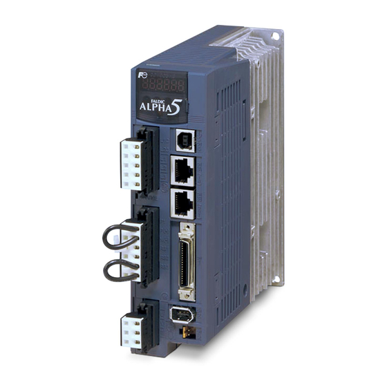
0.3.2 Servo Amplifier The model and serial number are also marked on the front panel of the main body of the servo amplifier. TYPE RYT401D5-VS2 SOURCE 1PH/3PH 200-230V 50or60Hz OUTPUT 3PH 400W SER. 693081A0021 Fuji Electric FA JAPAN 0-14 Model Nomenclature... - Page 33 CHAPTER 0 INTRODUCTION 0.4 Combination between Servomotor and Servo Amplifier 0.4.1 SX Type Use the servomotor and servo amplifier in one of the following sets. Do not use in other sets. Rated rotation Servo amplifier model Motor Capacity Motor model Frame speed model...
-
Page 34: Combination Between Servomotor And Servo Amplifier
CHAPTER 0 INTRODUCTION 0-16 Combination between Servomotor and Servo Amplifier... -
Page 35: Chapter 1 Installation
CHAPTER 1 INSTALLATION... -
Page 36: Servomotor
CHAPTER 1 INSTALLATION 1.1 Servomotor 1.1.1 Storage Environment Select the following environment when storing the servomotor, or when resting the machine under the state without power distribution. Item Environmental condition Ambient temperature -20 [°C] to +60 [°C] (no freezing allowed) Ambient humidity 10 [%] to 90 [%] RH (no condensation allowed) 1.1.2 Operating Environment... -
Page 37: Installing The Servomotor
CHAPTER 1 INSTALLATION 1.1.3 Installing the Servomotor The servomotor can be installed horizontally or vertically with the shaft facing up or down. The same rule applies to the brake-incorporated servomotor and gear head. The symbol in the figure is the installation method symbol specified by JEM. Description in parentheses ( ) indicates the earlier JEM symbol. -
Page 38: Servomotor Handling Precautions
CHAPTER 1 INSTALLATION 1.1.5 Servomotor Handling Precautions Do not hammer Do not give a strong impact on the output shaft of the servomotor. Otherwise the encoder inside the motor will be broken. Align the center when connecting with the machine system. Use a flexible coupling. Use rigid one designed exclusively for servomotors whenever possible. -
Page 39: Assembling Accuracy
CHAPTER 1 INSTALLATION 1.1.7 Assembling Accuracy The assembling accuracy of the servomotor is shown below. Unit: [mm] Runout at shaft Misalignment Perpendicularity of Servomotor model (flange) flange face Within 0.02 Within 0.06 Within 0.08 Perpendicularity of Misalignment Runout at shaft end flange face Servomotor... -
Page 40: Allowable Load
Radial load (Fr) Radial load Thrust load the shaft end Motor model Fr[N] Fs[N] LR[mm] GYS500D5-□B2(6) AC SERVO MOTOR Thrust load Fuji Electric FA JAPAN YM539189-1 GYS101D5-□B2(6) (Fs) GYS201D5-□B2(6) Servomotor at the shaft end (LR) GYS401D5-□B2(6) GYS751D5-□B2 GYS102D5-□B2 GYS152D5-□B2 GYS202D5-□B2 GYS302D5-□B2... -
Page 41: Cautionary Items On Servomotor Equipped With A Brake
CHAPTER 1 INSTALLATION 1.1.9 Cautionary Items on Servomotor Equipped with a Brake Brake noise The brake lining may issue chattering noise during operation of the motor equipped with a brake. As it is caused by brake structure and is not abnormal, the noise will not effect functional operation. Others (shaft end magnetization) The shaft end of the servomotor equipped with a brake is subject to leaking magnetic flux during energization of the brake coil (when the brake is released). -
Page 42: Servo Amplifier
CHAPTER 1 INSTALLATION 1.2 Servo Amplifier 1.2.1 Storage Environment Select the following environment when storing the servo amplifier, or when resting the machine under the state without power distribution. Item Environmental condition Ambient temperature -20 [°C] to +80 [°C] (no freezing allowed) Ambient humidity 10 [%] to 90 [%] RH (no condensation allowed) Indoors at altitude ≤... -
Page 43: Installing The Servo Amplifier
CHAPTER 1 INSTALLATION 1.2.3 Installing the Servo Amplifier (1) Install the servo amplifier vertically to the ground so that the "ALPHA5" characters (see the arrow in the figure on the right) on the front panel of the servo amplifier is horizontal. (2) Some parts of the servo amplifier generate heat during operation. -
Page 44: Depth Of Control Panel
CHAPTER 1 INSTALLATION (4) To improve air convection, reserve a clearance indicated in the diagram below between servo amplifiers or a distance to the peripheral equipment. 50[mm] or more 10[mm] or more 10[mm] or more 5[mm] or more 40[mm] or more 1.2.4 Depth of Control Panel Reserve 80 [mm] or a wider space in front of the servo amplifier which is connected with sequence I/O cables and encoder cable. -
Page 45: Chapter 2 Wiring
CHAPTER 2 WIRING... -
Page 46: Configuration
2.1.1 Part Name All wiring of the servo amplifier of 0.75 [kW] or less is connected via connectors. Servomotor GYS/GYC type 0.75kW or AC SERVO MOTOR less Fuji Electric FA YM539189-1 JAPAN Encoder cable Motor power cable (Lead 300 [mm]) - Page 47 CHAPTER 2 WIRING ■ Servomotor GYS/GYC type 1kW or more and GYG type Encoder connector Motor power connector Servo amplifier (frame 4) Keypad 6-digit 7-segment LED, 4 buttons, monitor terminals and one LED are installed. Analog monitor (CN6) The analog waveform is monitored. Power supply (TB1) USB (CN4) - Control power...
- Page 48 CHAPTER 2 WIRING Servo amplifier (frame 5, 6) Keypad 6-digit 7-segment LED, 4 buttons, monitor terminals and one LED are installed. Analog monitor (CN6) The analog waveform is monitored. USB (CN4) USB_B connector SX bus (CN3A (IN), CN3B (OUT)) Upper side: CN3A. Lower side: CN3B Charge LED Sequence I/O (CN1) Encoder wiring (CN2)
-
Page 49: Configuration
CHAPTER 2 WIRING 2.1.2 Configuration The figure on page 2-7 shows the general configuration of devices. There is no need to connect all devices. • The size on each device in the figure is not drawn at the uniform scale. (same as other chapters) •... - Page 50 CHAPTER 2 WIRING For servo amplifier frames 1, 2 and 3 (except for RYT***B5, C5) For lead wire type motors, connect cables as shown below. MCCB/ELCB PC (marketed item) The loader software can AC reactor be downloaded free of charge. Power filter (L1C, L2C) (USB)
- Page 51 CHAPTER 2 WIRING Connection Diagram (Servo amplifier frame 1, 2) Connect the external regenerative resistor across RB1 In case of commercial power and RB2. (Remove the short wire supply (single-phase 100V or from RB2-RB3.) single-phase 200V input), P(+) N(-) RB1 RB2 connect across L1 and L2 terminals.
- Page 52 CHAPTER 2 WIRING For servo amplifier frames 3 and 4 (except for 751D5 in frame 3) For Cannon connector type motors, connect cables as shown below. MCCB/ELCB AC reactor PC (marketed item) The loader software can be downloaded free Power filter of charge.
- Page 53 CHAPTER 2 WIRING Connection Diagram (Servo amplifier frame 3, 4) Connect the external regenerative resistor across RB1 and RB2. In case of commercial power (Remove the short wire from supply (single-phase 100V or RB2-RB3.) P(+) N(-) RB1 RB2 single-phase 200V input), connect across L1 and L2 terminals.
- Page 54 CHAPTER 2 WIRING In case of servo amplifier frames 5 or 6 For Cannon connector type motors, connect cables as shown below. MCCB/ELCB AC reactor PC (marketed item) The loader software can be downloaded free Servo amplifier of charge. Power filter (USB)...
- Page 55 CHAPTER 2 WIRING Connection Diagram (Servo amplifier frame 5, 6) Connect the external regenerative resistor across RB1 and RB2. (Remove the short wire from RB2-RB3.) P(+) N(-) RB1 RB2 Commercial power supply: 3-phase input 1(A) U M 2(B) V 3(C) W 4(D) DC24V 1(E) Br...
-
Page 56: Sequence I/O
CHAPTER 2 WIRING 2.1.3 Sequence I/O The wiring connector is not included in the servo amplifier. Connector kit type: WSK-D36P MON1 *FFA MON2 *FFB *FFZ OUT1 OUT2 CONT1 CONT2 CONT5 19 COMOUT 20 COMIN CONT3 CONT4 Terminal Function symbol Pull-up power input for pulse input 12 to 24 [V] DC Pulse input (for VS type, counter function only) Max. - Page 57 CHAPTER 2 WIRING Terminal Function symbol CONT1 Sequence input (For sink/source) CONT2 Supply command signals to the servo amplifier through these terminals. CONT3 12 [V] to 24 [V] DC/20 [mA] (per point). CONT4 Photo coupler isolated. The reference potential is the COMIN terminal. CONT5 (Soft filter 0.5 [ms], agreement of two scans, except for interrupt input) COMIN...
-
Page 58: Pulse Input (Ppi, Ca, *Ca, Cb, *Ca)
CHAPTER 2 WIRING 2.1.3.1 Pulse Input (PPI, CA, *CA, CB, *CA) Pulse input terminal • Format: Command pulse/direction, forward/reverse pulse, A/B phase pulse (parameter switch) • Max. input frequency: 1MHz (differential output), 200kHz (open collector output) A/B phase pulse indicates the frequency after multiplication by four. It is always a multiple of four. (1) Differential output Do not use the PPI terminal. -
Page 59: Pulse Output (Ffa, *Ffa, Ffb, *Ffb, Ffz, *Ffz)
CHAPTER 2 WIRING 2.1.3.2 Pulse Output (FFA, *FFA, FFB, *FFB, FFZ, *FFZ) The FFA, *FFA, FFB, and *FFB signals are output in a pulse proportionate to motor revolutions as two signals having a 90-degree phase difference (A/B phase pulse). The number of output pulses per motor revolution can be specified in a parameter. The output frequency is in proportion to the rotation speed of the shaft. -
Page 60: Sequence Input (Cont1, Cont2, Cont3
CHAPTER 2 WIRING 2.1.3.5 Sequence Input (CONT1, CONT2, CONT3, ... COMIN) The sequence input supports sink input and source input. A current of 24 [V] DC/20 [mA] is consumed at each point. The ON/OFF effect of the terminal can be changed with a parameter. Therefore only necessary signals can be assigned. - Page 61 CHAPTER 2 WIRING ONL 0 1 2 3 4 5 6 7 ONL 0 1 2 3 4 5 6 7 APS30 SCPU32 SCPU32 Wrap plug EMG +OT -OT SX ERR 8 9 101112131415 ERR 8 9 101112131415 TERM TERM STOP STOP LOADER...
- Page 62 CHAPTER 2 WIRING (3) SX bus transmission distance The SX bus supports the length up to 25 [m] as standard. If you need longer distance, you can use a SX bus electrical repeater unit: NP2L-RP1 to extend 25 [m] in addition. Up to three SX bus electrical repeater units can be used and the extended length will be up to 100 [m] in total.
- Page 63 CHAPTER 2 WIRING (4) Degraded operation ALPHA5 supports degraded operation of MICREX-SX. If the parameter of the CPU module is set to degraded operation enable, system operation continues even if the control power of the amplifier is shut off. Degraded operation is set: Serious alarm with amplifier control power shut off (system stopped) Degraded operation is not set: Light alarm with amplifier control power shut off (system operation continued)
- Page 64 CHAPTER 2 WIRING IQ area (VS type) Address Command position (PC ← servo amplifier) Feedback position (PC ← servo amplifier) Feedback speed (1 word) /parameter current value (PC ← servo amplifier) Torque (1 word) /parameter current value (PC ← servo amplifier) Position data sampling timing (PC ←...
- Page 65 CHAPTER 2 WIRING IQ area (LS type) Address Command position/feedback position/position deviation Feedback speed Command torque (1 word) Alarm code Execution M code Data selection check Positioning address check Over write Read completion completion Position command Speed command (manual feed) /speed data (positioning data) Acceleration time data Deceleration time data Acceleration...
-
Page 66: Usb (Cn4)
CHAPTER 2 WIRING Data assigned in IQ area can be changed using 8 to 11 bits in data selection (word +14). If command position is selected in data selection, specifications become compatible with conventional FALDIC-α series. One bit has been added to data selection of Faldic-α series. When data assigned in IQ area has been updated in data selection (word +14), the data selection check (word +6) will be updated to the identical pattern. -
Page 67: P-N Junction
CHAPTER 2 WIRING 2.2 P-N Junction Directly connect the DC link voltage of two servo amplifiers to exchange power. In a system having a powering (driving) shaft and regenerating shaft such as the winder/unwinder unit, the power consumption of the entire system can be reduced. Do not supply main power to the servo amplifier on the other side of the P-N junction. -
Page 68: Servomotor
CHAPTER 2 WIRING 2.3 Servomotor There are wiring of the main body of the servomotor and that of the brake (servomotor equipped with a brake). CAUTION • Keep consistency in the phase order between the servomotor and servo amplifier. • Do not connect commercial power to the servomotor. Otherwise it may cause failure. 2.3.1 Brake Connector Connector kit type: WSK-M02P-E (servomotor side of GYC and GYS type 0.75 [kW] or less) The brake of the servomotor equipped with a brake is a non-exciting brake. -
Page 69: Encoder
CHAPTER 2 WIRING 2.4 Encoder 2.4.1 Encoder Wiring Cable Use a shielded cable for encoder wiring of the servomotor. The optional cable for the servomotor is a UL-rated cable having bend resistance. Use a regular twisted pair batch shield cable if the servomotor and cable do not move. Cross linked polyethylene vinyl sheath cable for robot travel (Daiden Co., Ltd.) RMCV-SB-A (UL2464) AWG#25/2P + AWG#23/2C (Twisted type) (For 10 [m] or smaller wiring length) -
Page 70: Encoder Cable
CHAPTER 2 WIRING 2.4.2 Encoder Cable To fabricate the encoder cable by yourself, take care of the following. • Do not install a relaying terminal block between the servo amplifier and motor. • Use a shielded cable. • Connect the shielded cable with the designated connector pin, connector shell or cable clamp on both sides. -
Page 71: Description Of I/O Signals
CHAPTER 2 WIRING 2.5 Description of I/O Signals 2.5.1 I/O Signals of VS Type List of input signals The signal assigned to the sequence input terminal or to IQ area can be specified with a parameter. Default Name Setting range Change value PA03_01 CONT1 signal assignment... -
Page 72: List Of Output Signals
CHAPTER 2 WIRING (3) Input signals fixed in IQ area (cannot be changed) Function Function Servo-on [S-ON] Interrupt input enable Forward command [FWD] Deviation clear Reverse command [REV] Free-run Homing [ORG] Toggle monitor 0 Forced stop [EMG] Toggle monitor 1 Alarm reset [RST] Position command operation Write command... -
Page 73: I/O Signals Of Ls Type
CHAPTER 2 WIRING Output signals fixed in IQ area (cannot be changed) Function Function Ready for servo-on [RDY] Toggle error In-position [INP] Toggle answer 0 Over write completion Toggle answer 1 Read completion Forced stop detection Alarm detection Z-phase detection Homing completion Interrupt position detection Zero deviation... - Page 74 CHAPTER 2 WIRING Name Setting range Default value Change PA03_13 CONT13 signal assignment PA03_14 CONT14 signal assignment PA03_15 CONT15 signal assignment 9 (IQ:ABS/INC) 1 to 76 PA03_16 CONT16 signal assignment 10 (IQ:EMG) PA03_17 CONT17 signal assignment PA03_18 CONT18 signal assignment PA03_19 CONT19 signal assignment Note: After the setting change, the parameters above are enabled after power cycle.
- Page 75 CHAPTER 2 WIRING Function list (sequence input signal, IQ area) Function Function Servo-on [S-ON] Pause Forward command [FWD] Positioning cancel Reverse command [REV] External braking resistor overheat Start positioning [START] Teaching Homing [ORG] Override enable Home position LS [LS] Override 1 Override 2 Override 4 ABS/INC...
-
Page 76: List Of Output Signals
CHAPTER 2 WIRING List of output signals Set the sequence output terminals or signals assigned to IQ area in parameters. Name Setting range Default value Change PA03_51 OUT1 signal assignment PA03_52 OUT2 signal assignment PA03_53 OUT3 signal assignment 1 (IQ:RDY) PA03_54 OUT4 signal assignment 2 (IQ:INP) PA03_55 OUT5 signal assignment... - Page 77 CHAPTER 2 WIRING Function list (sequence output signal, IQ area) Function Function Function 1 Ready for servo-on [RDY] 30 Data error 60 MD0 31 Address error 61 MD1 2 In-position [INP] 32 Alarm code 0 62 MD2 11 Speed limit detection 33 Alarm code 1 63 MD3 13 Over write completion...
-
Page 78: Signal Descriptions
CHAPTER 2 WIRING 2.5.3 Signal Descriptions Input signal Servo-on [S-ON]: Sequence input signal (Reference value 1) The signal makes the servomotor ready to rotate. Function The servomotor is ready to rotate while the servo-on [S-ON] signal remains turned on. When the servo-on signal is turned off, the gate for IGBT is turned off and the servomotor does not rotate. - Page 79 CHAPTER 2 WIRING LS type: The servomotor keeps rotating in the positive (negative-) direction while the forward command [FWD] (reverse command [REV]) signal remains turned on. Acceleration begins at the rising edge, while the trailing edge triggers deceleration. The motor rotates at a speed selected through combination of multi-step speed settings [X1] (= No.
-
Page 80: Start Positioning [Start]: Sequence Input Signal (Reference Value 4)
CHAPTER 2 WIRING Start positioning [START]: Sequence input signal (Reference value 4) Positioning motion is executed according to positioning data or IQ area data. This signal is enabled only for LS type. Function The positioning motion starts at the activating edge of the start positioning signal. Specify the positioning data number to be executed to the positioning address in word+14. - Page 81 CHAPTER 2 WIRING Relevant description (1) Backlash compensation Backlash in mechanical system can be compensated using the traveling unit amount of the servomotor output shaft. Name Setting range Default value Change PA2_30 Backlash compensation 0 to 200000 [pulse] Always (in increments of 1) The servomotor rotates with adding the amount of reference value each time the servomotor changes the direction of rotation.
-
Page 82: Homing [Org]: Sequence Input Signal (Reference Value 5)
CHAPTER 2 WIRING Homing [ORG]: Sequence input signal (Reference value 5) Homing position LS [LS]: Sequence input signal (Reference value 6) Interrupt input: Sequence input signal (Reference value 49) A homing motion is executed and the home position is determined. Function The rising edge of the homing signal starts a homing motion. - Page 83 CHAPTER 2 WIRING To perform homing, use up positive over-travel [+OT] and negative over-travel [-OT] signals to assure safety. Homing direction • Detection of over-travel signal If homing is started from position A in the figure above, the home position LS is detected and stoppage is caused.
-
Page 84: Over-Travel In Negative Direction [-Ot]: Sequence Input Signal
CHAPTER 2 WIRING • Home position LS signal edge selection (PA2_13) After the trailing edge of the LS is detected, the Z-phase signal after the home position LS is detected. • Deceleration operation for creep speed (PA2_15) Controlled stop is caused during homing upon detection of the home position LS (or reference signal for shift operation), followed by reverse rotation until the point before the home position LS is reached, and then homing is performed again at the creep speed. - Page 85 CHAPTER 2 WIRING Parameter setting To assign the +OT signal to a sequence input terminal, specify the corresponding value ("7") to the input terminal function setting parameter. For the -OT signal, specify ("8"). This signal is handled to be always turned on if it is not assigned to the sequence input terminal. This signal is operated at the normally closed contact when assigned to the sequence input terminal and at the normally open contact when assigned to IQ area.
-
Page 86: Abs/Inc: Sequence Input Signal (Reference Value 9)
CHAPTER 2 WIRING ABS/INC: Sequence input signal (Reference value 9) Set the ABS/INC of positioning data when starting using an immediate value from IQ area. This signal is enabled only for LS type. Function ABS/INC While the ABS/INC signal is turned off, the position data when the start positioning [START] signal is turned on is handled as an ABS (absolute position specification). -
Page 87: Forced Stop [Emg]: Sequence Input Signal (Reference Value 10)
CHAPTER 2 WIRING Forced stop [EMG]: Sequence input signal (Reference value 10) Used to forcibly stop the servomotor. Function (1) Forced stop The servomotor is forcibly stopped while the forced stop [EMG] signal remains turned off. This signal is enabled in all control modes and it is given the highest priority. Because the safety and detection speed are significant, the forced stop signal is generally connected to the servo amplifier directly. -
Page 88: Alarm Reset [Rst]: Sequence Input Signal (Reference Value 11)
CHAPTER 2 WIRING Alarm reset [RST]: Sequence input signal (Reference value 11) The alarm reset signal resets alarm detection of the servo amplifier. Function The sequence input signal resets alarm detection of the servo amplifier. The rising edge of the alarm reset [RST] signal resets alarm detection. By starting the test operation mode at the keypad, operating the PC Loader or turning the power on again, the alarm can be reset. -
Page 89: Acc0: Sequence Input Signal (Reference Value 14)
CHAPTER 2 WIRING Parameter setting To assign the VEL0 and VEL1 signals to IQ area (sequence input terminal), specify the corresponding value ("12" or "13") to the input terminal function setting parameter. This signal is handled to be always turned off if it is not assigned to the sequence input terminal. Relevant description If the VEL0 and VEL1 signals are not assigned to the sequence input terminal, speed data in word +10 and +11 are enabled. -
Page 90: Position Preset: Sequence Input Signal (Reference Value 16)
CHAPTER 2 WIRING Position preset: Sequence input signal (Reference value 16) The present command position and feedback position are preset (overwritten). Function The present command position and the present feedback position are made the reference value of PA2_19 (preset position) at the rising edge. However, the deviation is subtracted from the feedback position. -
Page 91: Torque Limit 0: Sequence Input Signal (Reference Value 19)
CHAPTER 2 WIRING Gain switch Control gain PA1_55: Position loop gain 1 PA1_56: Speed loop gain 1 PA1_57: Speed loop integration time constant 1 PA1_58: Feed forward gain 1 PA1_64: Position loop gain 2 PA1_65: Speed loop gain 2 PA1_66: Speed loop integration time constant 2 PA1_67: Feed forward gain 2 Parameter setting To assign the gain switch to IQ area (sequence input terminal), specify the corresponding value... - Page 92 CHAPTER 2 WIRING • Torque limit under speed control and position control The following settings can be specified as a limitation set on the torque. VS type LS type IQ area (4000H/300 [%]) Forward rotation torque limit (PA1_27), reverse rotation torque limit (PA1_28) Second torque limit (PA2_58) Third torque limit (PA2_60) If "0"...
-
Page 93: Immediate Value Continuation: Sequence Input Signal (Reference Value 22)
CHAPTER 2 WIRING Parameter setting To assign the torque limit signal to IQ area (sequence input terminal), specify the corresponding value ("19" or "20") to the input terminal function setting parameter. (LS type accepts "20" only.) If the torque limit signal is not assigned to the sequence input terminal, the settings of PA1_27 (forward rotation torque limit) and PA1_28 (reverse rotation torque limit) are always enabled. - Page 94 CHAPTER 2 WIRING Parameter setting To assign the immediate value continuation command to IQ area (sequence input terminal), specify the corresponding value ("22") to the input terminal function setting parameter. Relevant signal reference values include following. Assigned signal Immediate value continuation: sequence input signal Immediate value continuation completion: sequence output signal...
-
Page 95: Immediate Value Change: Sequence Input Signal (Reference Value 23)
CHAPTER 2 WIRING Immediate value change: Sequence input signal (Reference value 23) The target position and target speed of immediate data start can be changed at an arbitrary timing. This signal is enabled only for LS type. Function After immediate data operation is started and the in-position signal is turned off, the target position and target speed can be changed at an arbitrary timing. -
Page 96: Command Pulse Ratio 1: Sequence Input Signal (Reference Value 27)
CHAPTER 2 WIRING (2) Command position / command speed / ABS/INC (IQ area) Each piece of data can be changed arbitrarily. The data in the IQ area at the timing of activating edge of the immediate value continuation command is enabled. However, the ABS/INC signal retains the state enabled at the activating edge of the start positioning signal. -
Page 97: Proportional Control: Sequence Input Signal (Reference Value 29)
CHAPTER 2 WIRING Proportional control: Sequence input signal (Reference value 29) Proportional band control is adopted as a servo amplifier control method. Function With [S-ON] signal turned on, the signal will be turned on while the servomotor shaft is mechanically locked. If the proportional control is turned on during servomotor rotation, position control becomes unstable. -
Page 98: Positioning Cancel: Sequence Input Signal (Reference Value 32)
CHAPTER 2 WIRING Relevant description (1) Positioning cancel If positioning cancel (32) is executed while the pause (31) signal remains turned on, the positioning motion is canceled. (2) ABS/INC (positioning data) After the pause (31) signal is turned off, the remaining motion continues without relations to the absolute (ABS) or incremental (INC) mode of positioning data. -
Page 99: Teaching: Sequence Input Signal (Reference Value 35)
CHAPTER 2 WIRING Teaching: Sequence input signal (Reference value 35) The current position of the servomotor is written as position data in the positioning data. This signal is enabled only for LS type. Function The current command position of the servomotor is written as position data in the positioning data at the activating edge of the teaching signal. -
Page 100: Torque Control: Sequence Input Signal (Reference Value - )
CHAPTER 2 WIRING Torque control: Sequence input signal (Reference value - ) This signal is enabled only for VS type. Function The torque control is executed by setting a value in data area after turning the "torque control" and "forward or reverse command" on in IQ area. Relevant description (1) Maximum rotation speed If there is no load connected to the servomotor, the rotation speed is subject to a limitation on... -
Page 101: Override Enable: Sequence Input Signal (Reference Value 43)
CHAPTER 2 WIRING Override enable: Sequence input signal (Reference value 43) Override 1: Sequence input signal (Reference value 44) Override 2: Sequence input signal (Reference value 45) Override 4: Sequence input signal (Reference value 46) Override 8: Sequence input signal (Reference value 47) The rotation speed of the servomotor can be changed during operation. -
Page 102: Interrupt Input Enable: Sequence Input Signal (Reference Value 48)
CHAPTER 2 WIRING (2) Weight of override The weight can be changed, using PA2_36 to 39 (override 1/2/4/8). Default Name Setting range Change value PA2_36 Override 1 PA2_37 Override 2 0[%] to 150[%] Always (In increments of 1) PA2_38 Override 4 PA2_39 Override 8 If all the override 1/2/4/8 settings are turned on, the weight is 150 (10 + 20 + 40 + 80). - Page 103 CHAPTER 2 WIRING Relevant description (1) Interrupt traveling unit amount The traveling unit amount after the interrupt input signal is turned on is specified in PA2_20 (interrupt traveling unit amount). The timing chart is shown in the figure below. Rotation speed Time Position control Interrupt input enable...
-
Page 104: Deviation Clear: Sequence Input Signal (Reference Value 50)
CHAPTER 2 WIRING (4) Command input cumulative pulse latch function This function is enabled only for VS type. While PA2_92 is 4 through 7 and the interrupt position detection command (input signal: %QX*.15.10) in IQ area and interrupt input enable are turned on, an interrupt input is detected to retain the number of input cumulative pulses at that point. -
Page 105: Multi-Step Speed Selection [X1]: Sequence Input Signal (Reference Value 51)
CHAPTER 2 WIRING Multi-step speed selection [X1]: Sequence input signal (Reference value 51) Multi-step speed selection [X2]: Sequence input signal (Reference value 52) Multi-step speed selection [X3]: Sequence input signal (Reference value 53) The manual feed speed is specified. This signal is enabled only for LS type. Function The rotation speed while the forward command [FWD] (reverse command [REV]) signal is turned on is selected. -
Page 106: Edit Permission: Sequence Input Signal (Reference Value 55)
CHAPTER 2 WIRING Parameter setting To assign the free-run to IQ area (sequence input terminal), specify the corresponding value ("54") to the input terminal function setting parameter. This signal is handled to be always turned off if it is not assigned to the sequence input terminal. Edit permission: Sequence input signal (Reference value 55) Editing operation for parameters and so on is limited with an external sequence input signal. - Page 107 CHAPTER 2 WIRING Anti resonance frequency selection 0: Sequence input signal (Reference value 57) Anti resonance frequency selection 1: Sequence input signal (Reference value 58) Select the anti resonance frequency, which is a vibration suppressing control function. Function In a spring characteristic structure such as the robot arm and transfer machine, vibration is caused at the end of the workpiece upon sudden acceleration or deceleration of the motor.
-
Page 108: Toggle Monitor 0: Sequence Input Signal (Reference Value 75)
CHAPTER 2 WIRING Toggle monitor 0: Sequence input signal (Reference value 75) Toggle monitor 1: Sequence input signal (Reference value 76) This signal checks if communications between the SX controller and servo amplifier is properly carried out. Function Using the toggle monitor bit and toggle answer bit, the normality of communications data of SX bus can be checked. -
Page 109: Position Control: Sequence Input Signal (Reference Value -)
CHAPTER 2 WIRING VS type: Signals related to toggle monitor are assigned and fixed to IQ area. Address Signal Toggle monitor 0 %QX*.15.15 Toggle monitor 1 %QX*.15.14 Toggle answer 0 %IX*.9.15 Toggle answer 1 %IX*.9.14 Toggle error %QX*.8.5 The toggle monitor function can be disabled by the setting of parameter PA2_92. (VS type only) LS type: Signals related to toggle monitor are used by assigning them OUT and CONT signals in parameter as necessary. -
Page 110: Z-Phase Detection Command: Sequence Input Signal (Reference Value -)
CHAPTER 2 WIRING Z-phase detection command: Sequence input signal (Reference value -) The Z-phase detection is enabled while the signal is turned on. This signal is enabled only for VS type. Function If Z-phase of the servomotor is detected while the this function is activated, bit 6 in word 9 in IQ area (Z-phase signal detection) is turned on. -
Page 111: Output Signal
CHAPTER 2 WIRING Output signal Ready for servo-on [RDY]: Sequence output signal (Reference value 1) This signal is turned on if the servomotor is ready to operate. Function The ready for servo-on signal is turned on if the conditions shown in the table below are satisfied. Signal Function Signal name... -
Page 112: In-Position [Inp]: Sequence Output Signal (Reference Value 2)
CHAPTER 2 WIRING In-position [INP]: Sequence output signal (Reference value 2) This signal is turned on after a positioning motion is finished. Function (1) Status of in-position signal The state under position control is shown in the table below. Status of in-position signal Factor Sequence status If servo-on [S-ON] is turned off... - Page 113 CHAPTER 2 WIRING Rotation Speed PA1_32: Zero deviation range/In-position range Time Zero speed Zero deviation In-position (level) PA1_35: In-position judgment time In-position (single shot) ON PA1_34: In-position output time (VS type), In-position min. OFF time/single shot ON time (LS type) (3) Interrupt positioning Level: The signal is turned on if conditions (A) and (B) below are satisfied.
-
Page 114: Speed Limit Detection: Sequence Output Signal (Reference Value 11)
CHAPTER 2 WIRING Speed limit detection: Sequence output signal (Reference value 11) The signal is turned on if the rotation speed of the servomotor reaches the preset speed limit. Function The signal is output to an external device if the rpm of the servomotor reaches the preset speed limit. - Page 115 CHAPTER 2 WIRING Write command Over write completion (Parameter) You can change parameter reference values when the over write completion signal has been turned on. (2) Parameter read Select a parameter type in the data selection area. A parameter is loaded with the activation of read command according to the table below. When the read command is turned off, the read completion is also turned off.
- Page 116 CHAPTER 2 WIRING Write command Over write completion (Positioning data) You can change positioning data reference values when the over write completion signal has been turned on. (4) Positioning data read Positioning data is loaded with the activation of read command according to the table below. When the read command is turned off, the read completion is also turned off.
-
Page 117: Brake Timing: Sequence Output Signal (Reference Value 14)
CHAPTER 2 WIRING Brake timing: Sequence output signal (Reference value 14) The timing signal for applying or releasing the brake of the servomotor. The signal is turned on during operation, while it is turned off after operation is stopped. Function The brake timing output is turned off if the servo-on [S-ON] signal is turned off. - Page 118 CHAPTER 2 WIRING (2) Upon alarm Alarm detection Base signal Ready for servo-on [RDY] Brake timing output (3) Upon main power supply OFF Main power supply Base signal Ready for servo-on [RDY] Brake timing output 2-74 Description of I/O Signals...
-
Page 119: Alarm Detection (Normally Open Contact): Sequence Output Signal
CHAPTER 2 WIRING Alarm detection (normally open contact): Sequence output signal (Reference value 16) Alarm detection (normally closed contact): Sequence output signal (Reference value 76) Signals are turned on (off in case of normally closed contact) if the servo amplifier detects an alarm (activation of a protective function). - Page 120 CHAPTER 2 WIRING Point detection, area detection 1: Sequence output signal (Reference value 17) Point detection, area detection 2: Sequence output signal (Reference value 18) The current position of the servomotor is detected and output in these signals. This signal is enabled only for LS type. Function Three types of the output format can be selected through settings of PA2_31 (point detection, area detection).
-
Page 121: Limiter Detection: Sequence Output Signal (Reference Value 19)
CHAPTER 2 WIRING Limiter detection: Sequence output signal (Reference value 19) Whether the limiter function is enabled or not is checked. This signal is enabled only for LS type. Function With the limiter function, a motion started with positioning data exceeding the positive limiter detecting position (PA2_28) or negative limiter detecting position (PA2_29) is stopped at the detecting position. -
Page 122: Ot Detection: Sequence Output Signal (Reference Value 20)
CHAPTER 2 WIRING OT detection: Sequence output signal (Reference value 20) This signal is output if the over-travel (OT) signal is turned off. Function The OT detection ("20") sequence output is issued while the +OT (7) or -OT (8) sequence input signal terminal remains turned off. -
Page 123: Cycle End Detection: Sequence Output Signal (Reference Value 21)
CHAPTER 2 WIRING Cycle end detection: Sequence output signal (Reference value 21) Add a cycle end to positioning data to check if the data position is reached. PA2_41 (sequential start selection) must be set at “1” (enable). Change PA2_40 (internal positioning data selection) to “1” (enable). -
Page 124: Homing Completion: Sequence Output Signal (Reference Value 22)
CHAPTER 2 WIRING Relevant description The cycle end detection signal is not output if sequential start cannot be executed. • If the servo-on signal is turned off • If the pulse ratio is enabled or a homing cycle is executed during sequential operation •... -
Page 125: Zero Deviation: Sequence Output Signal (Reference Value 23)
CHAPTER 2 WIRING Zero deviation: Sequence output signal (Reference value 23) The signal is turned on if the deviation (deviation amount) retained in the servo amplifier becomes within the reference value under position control. Whether the servomotor has reached close to the command position can be checked. Function The signal is turned on if the difference (deviation amount) between the command position and feedback position is within the reference value of PA1_32 (zero deviation width/in-position range). -
Page 126: Torque Limit Detection: Sequence Output Signal (Reference Value 26)
CHAPTER 2 WIRING Parameter setting To assign the speed coincidence [NARV] signal to IQ area (sequence output terminal), specify the corresponding value ("25") to the output terminal function setting parameter. Relevant description PA1_25 (max. rotation speed (for position and speed Control)) Specify the upper limit of the servomotor rotation speed which is specified with a parameter. - Page 127 CHAPTER 2 WIRING Standard series Overload warning time (at 3000r/min) 1200 1000 Overload warning value=20% Overload warning value=40% Overload warning value=60% Overload warning value=80% Overload warning value=100% Overload detection (OL2) alarm Lock detection (OL1) alarm Load factor [%] Overload warning time (at 6000r/min) Overload warning value=20% Overload warning value=40% Overload warning value=60%...
-
Page 128: Servo Control Ready [S-Rdy]: Sequence Output Signal (Reference Value 28)
CHAPTER 2 WIRING Servo control ready [S-RDY]: Sequence output signal (Reference value 28) Use the signal to check that the servo amplifier and servomotor operate correctly. Function The servo control ready signal remains turned on while the conditions listed in the table below are satisfied. -
Page 129: Data Error: Sequence Output Signal (Reference Value 30)
CHAPTER 2 WIRING Parameter setting To assign the edit permission response to IQ area (sequence output terminal), specify the corresponding value ("29") to the output terminal function setting parameter. Relevant description For details, refer to "Edit permission" on page 2-62. Data error: Sequence output signal (Reference value 30) The signal is turned on if the data reading or writing process between the SX controller and servo amplifier does not proceed correctly. -
Page 130: Alarm Code 0: Sequence Output Signal (Reference Value 32)
CHAPTER 2 WIRING Alarm code 0: Sequence output signal (Reference value 32) Alarm code 1: Sequence output signal (Reference value 33) Alarm code 2: Sequence output signal (Reference value 34) Alarm code 3: Sequence output signal (Reference value 35) Alarm code 4: Sequence output signal (Reference value 36) Upon alarm, signal to output alarm details into code Function Alarm code 0 to 4 signals assigned to OUT output signals identifies the nature of the alarm. - Page 131 CHAPTER 2 WIRING List of alarm nature and code Nature of alarm ALM4 ALM3 ALM2 ALM1 ALM0 Code Indication Order No alarm (during correct operation) Overload 1 Overload 2 Command pulse frequency error Amplifier overheat Internal braking resistor overheat External braking resistor overheat Braking transistor error Deviation overflow Overcurrent 1...
-
Page 132: Ot Detection: Sequence Output Signal (Reference Value 38)
CHAPTER 2 WIRING Type Nature of alarm Code BCD error Address error Out-of-range error Command rejection BCD error Data error Out-of-range error, 0 data write Negative sign designation Battery warning Maintenance function Life warning • If two or more alarms occur simultaneously, alarms are output in the priority specified in the table above. -
Page 133: Home Position Ls Detection: Sequence Output Signal (Reference Value 40)
CHAPTER 2 WIRING Home position LS detection: Sequence output signal (Reference value 40) The signal is output while the home position LS signal (input signal) remains turned on. Function The sequence output corresponding to home position LS detection is turned on while the home position LS sequence input signal remains turned on. -
Page 134: Life Warning: Sequence Output Signal (Reference Value 46)
CHAPTER 2 WIRING Life warning: Sequence output signal (Reference value 46) The life of internal main circuit capacitors of the servo amplifier and that of the cooling fan are calculated and output its signal. Function The life of internal main circuit capacitors of the servo amplifier and that of the cooling fan are calculated and, if either exceeds the rated time, a life warning is turned on. - Page 135 CHAPTER 2 WIRING Simultaneous output of M code Rotation M code 20 speed Time Timer (positioning data) Ready for servo-on Start positioning AD7 to AD0 In-position (level) M code * Positioning data is executed while the timer time is counted . * The default value of the M code is FF.
-
Page 136: Position Preset Completion: Sequence Output Signal (Reference Value 75)
CHAPTER 2 WIRING Output after M code issuing Rotation M code 20 speed Time Timer (positioning data) Ready for servo-on Start positioning AD7 to AD0 In-position (level) M code * Positioning data is executed while the timer time is counted . * The default value of the M code is FF. -
Page 137: Immediate Value Continuation Permission: Sequence Output Signal
CHAPTER 2 WIRING Immediate value continuation permission: Sequence output signal (Reference value 79) The signal is turned on when the system is ready to accept an immediate value continuation command. This signal is enabled only for LS type. Function The immediate value continuation command can be accepted only if this signal is turned on after immediate data operation is started. - Page 138 CHAPTER 2 WIRING Immediate value change completion: Sequence output signal (Reference value 81) The signal is turned on when the changing process is executed according to an immediate value change signal, and it is turned off after the immediate value change is turned off. This signal is enabled only for LS type.
- Page 139 CHAPTER 2 WIRING If the command positioning completion signal is assigned to an output signal, the condition for the next start signal is activation of the command positioning completion signal. Refer to the timing chart below. (Example : Positioning continuation) Speed Motor speed...
-
Page 140: Conta Through: Sequence Output Signal (Reference Value 91)
CHAPTER 2 WIRING CONTa Through: Sequence output signal (Reference value 91) CONTb Through: Sequence output signal (Reference value 92) The signals input to IQ area on the SX controller side can be output to the OUT signal of the servo amplifier. -
Page 141: Internal Command Pulse Zero: Sequence Output Signal (Reference Value -)
CHAPTER 2 WIRING Internal command pulse zero: Sequence output signal (Reference value -) The signal is turned on when the position command (unit: encoder pulse amount) inside the amplifier becomes zero. The signal can be output to IQ area (%IX*.9.8). This signal is enabled only for VS type. - Page 142 CHAPTER 2 WIRING 2-98 Description of I/O Signals...
-
Page 143: Chapter 3 Operation
CHAPTER 3 OPERATION... -
Page 144: Signal Description (Priority Among Input Signals)
CHAPTER 3 OPERATION 3.1 Signal Description (Priority among Input Signals) Input signals of the servo amplifier for stopping the motor shaft are received first in view of safety. Applicable signal Description (Function No.) Free-run command (54) 01 Operation signal always given highest priority Servo-on (1) Forced stop (10) 02 Operation signal always given priority... -
Page 145: Operation Check
CHAPTER 3 OPERATION 3.2 Operation Check 3.2.1 Power-On Connect the commercial power supply and the servomotor to the servo amplifier. For the wiring method, refer to "CHAPTER 2 WIRING." Supplying commercial power Operate MCCB/ELCB to supply power. Supply main power simultaneously or later to the control power. If necessary, insert an electromagnetic contactor in the upstream of the main power input so that the power can be shut off at any time. -
Page 146: Power-On/Servo Control-Ready [S-Rdy]
CHAPTER 3 OPERATION If the keypad indicates differently If three characters from the left is "AL-," an alarm is detected. In this case, the display blinks. In addition, the orange LED below the keypad blinks upon an alarm. If the keypad shows those other than specified above, the servo amplifier is not in the factory shipment state. -
Page 147: Test Operation At Keypad
CHAPTER 3 OPERATION 3.2.4 Test Operation at Keypad Using the test operation mode of the keypad, check the motor rotation. In case of a servomotor equipped with a brake, supply 24 [V] DC to release the brake. The motor rotates even without a sequence I/O signal. The relevant parameter settings and default values are shown below. -
Page 148: If The Servomotor Fails To Start
CHAPTER 3 OPERATION 3.2.5 If the Servomotor Fails to Start If the servomotor fails to start or unexpected indication is given, it is recommended to undergo the procedure described in “13.5.8 Diagnosis to be Made If the Servomotor Fails to Start” on page 13-29, using PC Loader. -
Page 149: Operation With Vs Type
CHAPTER 3 OPERATION 3.3 Operation with VS Type This section describes the VS type (RST □□□□5-VS□) servo amplifier. The servo amplifier occupies 16 words of the IQ area. 3.3.1 IQ Area Select the individual module and servo in the system definition of D300win. Designate an arbitrary station number. -
Page 150: Servo-On [S-On]/ Ready For Servo-On [Rdy]
CHAPTER 3 OPERATION 3.3.2 Servo-On [S-ON]/ Ready for Servo-on [RDY] The servo amplifier becomes operable about 2.0 seconds after the control power and motor power are supplied. Turn on servo-on [S-ON] (%QX*.14.15) to supply power to the servomotor to make it ready to rotate. After servo-on is turned on and the motor becomes ready to rotate, the ready for servo-on [RDY] (%IX*.8.15) signal is turned on to indicate that the motor is ready to rotate. - Page 151 CHAPTER 3 OPERATION Turn on servo-on [S-ON] and position control (%QX*.14.9) to stop with the servo locked. The position command remains enabled after the activating edge while position command operation is turned on. Change the position command (%QD*.10) after in-position (%IX*.8.14) is turned off. Speed [RDY] Position control...
-
Page 152: Operation Under Speed Control
CHAPTER 3 OPERATION The toggle error is not a detected alarm. The toggle error is detected after the toggle is executed even once. Issue an alarm reset signal after toggle restart to reset from the toggle error. • Command position (%ID*.0) The position command that is given through the SX bus and interpolated at the servo amplifier control period into the latest command position is output. -
Page 153: Interrupting/Stopping Operation
CHAPTER 3 OPERATION 3.3.7 Interrupting/Stopping Operation The following input signals interrupt or stop each operation. ・Servo-on [S-ON] ・+OT/-OT ・Forced stop [EMG] ・Positioning cancel ・Deviation clear ・Free-run (1) Servo-on [S-ON] If servo-on [S-ON] is turned off during motor rotation, operation is stopped and the motor is stopped according to the setting of parameter PA2_61 (action sequence at servo-on OFF). - Page 154 CHAPTER 3 OPERATION (2) +OT/-OT / positive software OT / negative software OT If +OT or -OT is detected during motor rotation (inactive due to normally closed contacts) or positive software OT or negative software OT is detected, operation is stopped and immediate controlled stop is caused according to the torque specified in extended function parameter PA2_60 (third torque limit).
- Page 155 CHAPTER 3 OPERATION (3) Forced stop [EMG] If forced stop [EMG] is detected during motor rotation, operation is stopped and immediate controlled stop is caused according to the torque specified in extended function parameter PA2_60 (third torque limit). While forced stop [EMG] is detected, the motor is stopped at the zero speed and the current position is not retained.
- Page 156 CHAPTER 3 OPERATION (4) Positioning cancel If the positioning cancel signal is turned on during motor rotation, operation is stopped and controlled stop is caused according to the deceleration time setting. While the positioning cancel signal remains active, homing or position command operation does not start. The signal is disabled for speed operation.
- Page 157 CHAPTER 3 OPERATION (6) Free-run While the free-run signal is turned on, outputs of the servo amplifier are turned off and the servomotor coasts to stop (at zero torque). (The motor rotation is not controlled.) If the free-run signal is turned on during motor rotation, operation is stopped and the motor keeps rotating due to the inertia of the load.
-
Page 158: Writing A Parameter
CHAPTER 3 OPERATION 3.3.8 Writing a Parameter To read or write parameters, change the SEL2, SEL1 and SEL0 bits to those specified in the table below. Reading or writing is made at the activating edge of the read command or write command bit. Designate the parameter number in low order bits of word +14. - Page 159 CHAPTER 3 OPERATION Bit command (word position 14) Name Bit position Function While the bit is turned on, the motor is turned on to be ready to Servo-on [S-ON] operate. Forward command While the bit is turned on under position or speed control, the [FWD] motor rotates.
- Page 160 CHAPTER 3 OPERATION Name Bit position Function Write command Parameter write command Read command Parameter read command Bit data (8 word) Name Bit position Function Ready for The bit is turned on when the servomotor is ready to rotate. servo-on [RDY] The bit is turned off if position command operation is turned on In-position and the position command can be updated.
- Page 161 CHAPTER 3 OPERATION Bit data (9 word) Name Bit position Function Toggle answer 0 Refer to the description about toggle monitor in the text. Toggle answer 1 CONT1 Through CONT2 Through The status of the sequence input terminal is output without CONT3 Through changes.
-
Page 162: Selecting The Monitor
CHAPTER 3 OPERATION 3.3.9 Selecting the Monitor Enter the parameter address to select the active monitor. Use bit settings of words +14 and +15 in the following IQ address to select the monitor as shown in the table on the next page. Address Command position (PC ←... - Page 163 CHAPTER 3 OPERATION ① ② ③ ④ Address Data format Data Parameter selection address (+14) [00□□□□□□] Feedback speed Command torque [01□□□□□□] Feedback speed: [10 □□□000] Feedback speed 4000'H/3000r/min or 3000'H/3000r/min (signed) [10 □□□001] Command speed: Command speed 4000'H/3000r/min or 3000'H/3000r/min (signed) [10 □□□010] Command torque: Command torque...
-
Page 164: Operation With Ls Type
CHAPTER 3 OPERATION 3.4 Operation with LS Type This section describes the LS type (RYT□□□□5-LS□) servo amplifier. The servo amplifier occupies 16 words of the IQ area. 3.4.1 IQ Area Register the servo and RYS-LS/RYT-LS linear positioning in the system definition of SX-Programmer Expert. - Page 165 CHAPTER 3 OPERATION The following signals are assigned if the input terminal function parameters and output terminal function parameters are in the default states (bit data at word 7, bit command at word 15). Address Command position/feedback position/deviation current value/ parameter read value/position data (positioning data)/LS-Z pulse Feedback speed/speed data (positioning data)/command speed/ torque current value/motor feedback current value/peak torque/effective torque...
- Page 166 CHAPTER 3 OPERATION Details of I/O signals in IQ area Address Command position/feedback position/position deviation (Low order word) Command position/feedback position/position deviation (High order word) Feedback speed (Low order word) Feedback speed (High order word) Command torque (1 word) Alarm code Execution M code Data selection check Positioning address check...
- Page 167 CHAPTER 3 OPERATION Address Command position/feedback position/position deviation (Low order word) Command position/feedback position/position deviation (High order word) Monitor 1 (Low order word) Monitor 1 (High order word) Monitor 2 (1 word) Alarm code - Data selection check Monitor 1 and 2 selection check -...
- Page 168 CHAPTER 3 OPERATION Address Command position/feedback position/position deviation (Low order word) Command position/feedback position/position deviation (High order word) Feedback speed (Low order word) Feedback speed (High order word) Command torque (1 word) Alarm code - Data selection check Vibration suppressing workpiece inertia ratio check -...
- Page 169 CHAPTER 3 OPERATION Address Read parameter (Low order word) Read parameter (High order word) - - - - - Data selection check Parameter no. check - Over write Read OUT3 OUT4 OUT5 OUT6 OUT7 OUT8 OUT9 OUT10 OUT11 OUT12 OUT13 OUT14 OUT15 OUT16 completion completion Write parameter (Low order word)
- Page 170 CHAPTER 3 OPERATION Address Read position data (Low order word) Read position data (High order word) Read speed data (Low order word) Read speed data (High order word) Read timer data Read attribute Read M code Data selection check Positioning data no. check -...
- Page 171 CHAPTER 3 OPERATION Allocation of IQ area ・Acceleration/deceleration time rate You can designate the actual Acceleration Deceleration Acceleration time Deceleration time time rate time rate acceleration/deceleration time 0:PA1_37, PA1_39 0:PA1_38, PA1_40 according to this multiplication 1 to 255:0.1 to 25.5ms 1 to 255:0.1 to 25.5ms 0 to 255:0 to 255ms 0 to 255:0 to 255ms...
- Page 172 CHAPTER 3 OPERATION Setting and display unit Data item Unit Setting range Command 1 [unit amount], signed - position Feedback position 1 [unit amount], signed - Position deviation 1 [pulse], signed - Feedback speed 1 [r/min], signed - Command torque 1 [%], signed -...
-
Page 173: Immediate Data Operation
CHAPTER 3 OPERATION 3.4.2 Immediate data operation Use position data setting at words 8 and 9 and speed data setting at words 10 and 11 to execute immediate data operation. When in-position [INP] is turned on, immediate data operation is executed at the activating (rising) edge of start positioning [START]. - Page 174 CHAPTER 3 OPERATION Speed data setting Speed Position data setting Time [RDY] [INP] [OFF, OFF, OFF, OFF] [CSEL3, 2, 1, 0] [OFF, OFF, OFF, OFF] [SEL3, 2, 1, 0] 10000 [unit amount] Position data setting 50000 [×0.01 r/min] Speed data setting 200 [×acceleration time rate] Acceleration time data [0,1](→×1 ms)...
- Page 175 CHAPTER 3 OPERATION You can perform “immediate value change operation” to change the target stopping position during immediate data operation. Change position data setting (words 8 and 9) and speed data setting (words 10 and 11) and turn the immediate value change command on during immediate data operation to change operation.
- Page 176 CHAPTER 3 OPERATION Perform “immediate value continuation operation” to designate the next target stopping position during immediate data operation and continue operation. Specify the position data setting (words 8 and 9) and speed data setting (words 10 and 11) during immediate data operation and turn the immediate value continuation command on to execute (continue) immediate data operation.
-
Page 177: Positioning Data Operation
CHAPTER 3 OPERATION Speed Time Immediate value continuation Immediate value continuation permission 50ms 50ms 3.4.3 Positioning Data Operation Enter “1” as an automatic operation setting parameter (internal positioning data selection (PA2_40)) to execute positioning data operation. Specify the positioning data number to be executed as a positioning address at bits 7 to 0 of word 14 and turn start positioning [START] on to execute positioning. - Page 178 CHAPTER 3 OPERATION (1) Acceleration and deceleration follow the settings of basic setting parameters PA1_37 to 40 and input signal ACC0. (2) Positioning data operation can be executed if data selection [SEL 3, 2, 1 and 0] is specified as shown below.
-
Page 179: Pulse Operation
CHAPTER 3 OPERATION Positioning data operation can be continued upon a single input of start positioning [START] with positioning of continuous numbers (continuous data operation). For the setting method, refer to “CHAPTER 12 POSITIONING DATA.” 3.4.4 Pulse Operation Pulse operation can be performed when either command pulse ratio 1 or 2 is turned on. Use command pulse ratios 1 and 2 to the CONT signal with input terminal function parameters. -
Page 180: Interrupting/Stopping Operation
CHAPTER 3 OPERATION The number of motor travel pulses corresponding to each input pulse is obtained in the equation below. 1 input pulse × command pulse ratio 1 × (numerator 0 of electronic gear / denominator of electronic gear) = number of motor travel pulses (example with command pulse ratio 1 input turned on) Operation follows the frequency and pulse count of the supplied pulse. - Page 181 CHAPTER 3 OPERATION (1) Servo-on [S-ON] If servo-on [S-ON] is turned off during motor rotation, operation is stopped and the motor is stopped according to the setting of parameter PA2_61 (action sequence at servo-on OFF). If immediate deceleration is selected, deceleration is made at the torque specified in parameter PA2_60 (third torque limit).
- Page 182 CHAPTER 3 OPERATION (2) +OT/-OT / positive software OT / negative software OT If +OT or -OT is detected during motor rotation (inactive due to normally closed contacts) or positive software OT or negative software OT is detected, operation is stopped and immediate controlled stop is caused according to the torque specified in extended function parameter PA2_60 (third torque limit).
- Page 183 CHAPTER 3 OPERATION (3) Forced stop [EMG] If forced stop [EMG] is detected during motor rotation, operation is stopped and immediate controlled stop is caused according to the torque specified in extended function parameter PA2_60 (third torque limit). While forced stop [EMG] is detected, the motor is stopped at the zero speed and the current position is not retained.
- Page 184 CHAPTER 3 OPERATION (4) Pause If the pause signal is turned on during homing, interrupt positioning, immediate data operation or positioning data operation, operation is interrupted and the motor is stopped while the signal remains turned on. After the signal is turned off, the operation continues. In-position [INP] is not turned on in a pause.
- Page 185 CHAPTER 3 OPERATION (1) Acceleration/deceleration follows the settings of basic setting parameters PA1_37 through 40 and the state of input signal ACC0, or the settings of acceleration/deceleration time data (IQ area). (2) The in-position [INP] signal shown in the figure indicates the state in the level output mode.
- Page 186 CHAPTER 3 OPERATION (7) Free-run While the free-run signal is turned on, outputs of the servo amplifier are turned off and the servomotor coasts to stop (at zero torque). (The motor rotation is not controlled.) If the free-run signal is turned on during motor rotation, operation is stopped and the motor keeps rotating due to the inertia of the load.
- Page 187 CHAPTER 3 OPERATION (8) Positive limiter detection / negative limiter detection If the limiter detection position (PA2_28, PA2_29) is set, operation is canceled before exceeding the target positon and stopped at positive/negative limiter detection position. Speed Automatic operation setting parameter Positive limit detection position (PA2_28) Time [RDY]...
-
Page 188: Reading/Writing A Parameter
CHAPTER 3 OPERATION 3.4.6 Reading/writing a Parameter To read or write a parameter, enter the SEL3, SEL2, SEL1 and SEL0 bits as shown in the table below and switch the IQ area of the SX bus to that of parameter reading/writing, and designate the page to be edited (PA*_) and number and set the data. - Page 189 CHAPTER 3 OPERATION (1) Parameter read Parameter data is read by the read command (0 bit in 15th word). [SEL3, 2, 1, 0] [OFF, OFF, ON, ON] → PA1_ Parameter no. [Set] Read command [CSEL3, 2, 1, 0] [OFF, OFF, ON, ON] → PA1_ Parameter no.
- Page 190 CHAPTER 3 OPERATION (3) Parameter read/write error If parameter read/write fails, a data error is turned on instead of read/write completion. If a data error is turned on, correct setting items and execute read/write again. [SEL3, 2, 1, 0] [OFF, OFF, ON, ON] → PA1_ Parameter no.
-
Page 191: Reading/Writing A Positioning Data
CHAPTER 3 OPERATION 3.4.7 Reading/writing a Positioning Data To read or write a positioning data, enter the SEL3, SEL2, SEL1 and SEL0 bits as shown in the table below and switch the IQ area of the SX bus to that of positioning data reading/writing, and designate the number to be edited (address) and set the positioning data. - Page 192 CHAPTER 3 OPERATION (1) Positioning data read Positioning data is read by the read command (0 bit in 15th word). [SEL3, 2, 1, 0] [OFF, ON, ON, OFF] Positioning address Read command [CSEL3, 2, 1, 0] [OFF, ON, ON, OFF] Positioning address [Check] Read completion Position data [Read]...
- Page 193 CHAPTER 3 OPERATION (2) Positioning data write Positioning data is written by the write command (0 bit in 15th word). [SEL3, 2, 1, 0] [OFF, ON, ON, OFF] Positioning address Position data 10000 Speed data 2500 Stand still timer M code output timing ON = Output at completion M code selection ON = Enable...
- Page 194 CHAPTER 3 OPERATION (3) Positioning data read/write error If positioning data read/write fails, a data error is turned on instead of read/write completion. If a data error is turned on, correct setting items and execute read/write again. [SEL3, 2, 1, 0] [OFF, ON, ON, OFF] Positioning address Position data...
-
Page 195: Selecting The Monitor
CHAPTER 3 OPERATION 3.4.8 Selecting the Monitor Enter the parameter address to select the active monitor. Use bit settings of words +14 and +15 in the following IQ address to select the monitor as shown in the table on the next page. Address Command position/feedback position/position deviation Monitor area +2, +3... - Page 196 CHAPTER 3 OPERATION ① ② ③ Parameter address Address +2, 3 (DINT-type) Data format Address +4 (INT-type) [00 □□□□□□] Feedback speed Command torque [01 □□□□□□] [10 □□□000] Feedback speed 1r/min, signed [10 □□□001] Command speed 1r/min, signed [10 □□□010] Command torque 1%, signed [10 □□□011] Motor current...
-
Page 197: Chapter 4 Parameter
CHAPTER 4 PARAMETER... -
Page 198: Parameter Division
CHAPTER 4 PARAMETER 4.1 Parameter Division CAUTION • Never add an extreme change to parameters. Otherwise machine motion will become unstable. Risk of injuries Parameters of the ALPHA5 servo amplifiers are divided into the following setting items according to the function. - Page 199 CHAPTER 4 PARAMETER Record of Control mode Name Default value Power reference PA1_ value Position Speed Torque Output pulse phase selection at CCW rotation Z-phase position offset Tuning mode selection Load inertia ratio Auto tuning gain 1 Auto tuning gain 2 Easy tuning: stroke setting 2.00 Easy tuning: speed setting...
-
Page 200: Description Of Each Parameter
CHAPTER 4 PARAMETER 4.2.2 Description of Each Parameter PA1_02 INC/ABS system selection Default Name Setting range Change value INC/ABS selection 0: Incremental system 1:Absolute system 2: Non-overflow absolute system Power (not detect the multi-turn overflow) Select either the relative position (incremental) system or absolute position system. Reference Function Description... - Page 201 CHAPTER 4 PARAMETER Command pulse / sign (reference value of parameter 03: 0) The command pulse indicates the rotation amount (CA, *CA), while the command sign (CB, *CB) indicates the direction of rotation. If (CB) is at the low level and (*CB) is at the high level, a forward direction command is issued. Differential input Forward rotation command Reverse rotation command...
-
Page 202: Pa1_04 Rotation Direction Selection
CHAPTER 4 PARAMETER A/B phase pulse (reference value of parameter 03: 2) The A-phase signal (CA, *CA) and B-phase signal (CB, *CB) indicate the direction of rotation and rotation amount, respectively. Each edge of the A-phase and B-phase signals corresponds to one pulse. (It is four-fold frequency in the amplifier.) ・Differential input Forward rotation command... -
Page 203: Pa1_05 Number Of Command Input Pulses Per Revolution
CHAPTER 4 PARAMETER Forward/Reverse rotation Forward rotation The servomotor rotates forward if it rotates counterclockwise (CCW: figure on the right) when the output shaft is viewed from the front. Clockwise rotation is reverse rotation. PA1_05 Number of command input pulses per revolution Default Name Setting range... - Page 204 CHAPTER 4 PARAMETER Entering from PC Loader Use the "Mechanical settings calculation (T)" button provided at the lower part of the parameter editing screen (PA1: Basic setting) of PC Loader to specify the electronic gear simply. Enter the specifications of the machine to automatically calculate the settings.
-
Page 205: Pa1_08 Number Of Output Pulses Per Revolution
CHAPTER 4 PARAMETER PA1_08 Number of output pulses per revolution Default Name Setting range Change value Number of output 0: Entered values at PA1_09 and _10 are enabled. 2048 Power pulses per 16 to 262144 [pulses]: Number of command input revolution pulses per revolution is enabled. -
Page 206: Pa1_11 Output Pulse Phase Selection At Ccw Rotation
CHAPTER 4 PARAMETER PA1_11 Output pulse phase selection at CCW rotation Default Name Setting range Change value Output pulse phase 0: B-phase pulse lead at CCW rotation Power selection at CCW 1: A-phase pulse lead at CCW rotation rotation The phase of the output pulse of the servomotor is adjusted to the traveling direction of the machine. Select the phase of forward rotation (CCW rotation) of the servomotor. -
Page 207: Pa1_13 Tuning Mode Selection
CHAPTER 4 PARAMETER PA1_13 Tuning mode selection Default Name Setting range Change value 0: Auto tuning 1: Semi-auto tuning Tuning mode selection Always 2: Manual tuning 3: Interpolation control mode This parameter is enabled under position and speed control. Select the tuning method of the servo amplifier. Refer to the following description to select the mode. Auto tuning (default value) In this mode, the ratio of moment of inertia of the load of the machine is always assumed inside the amplifier and the gain is automatically adjusted to the best one. -
Page 208: Pa1_14 Load Inertia Ratio
CHAPTER 4 PARAMETER Parameters that must be entered in each tuning mode and automatically adjusted parameters are shown below. Tuning mode selection Name PA1_ 3: Interpolation 0: Auto 1: Semi-auto 2: Manual control Load inertia ratio Auto tuning gain 1 Moving average S-curve time Position command response time constant... -
Page 209: Pa1_15 Auto Tuning Gain
For the moment of inertia calculation method, refer to "CHAPTER 14 APPENDICES." • The value is automatically calculated with the capacity selection software (visit Fuji Electric's home page to download). PA1_15 Auto tuning gain 1... -
Page 210: Pa1_16 Auto Tuning Gain 2
CHAPTER 4 PARAMETER PA1_16 Auto tuning gain 2 Default Name Setting range Change value Auto tuning gain 2 1 to 12 (in increments of 1) Always This parameter is enabled only under position control. The parameter is enabled if PA1_13 (tuning mode selection) is 0 (auto tuning) or 1 (semi-auto tuning). This parameter adjusts the command response. -
Page 211: Pa1_20 To 23 Easy Tuning Settings
CHAPTER 4 PARAMETER PA1_20 to 23 Easy tuning settings Default Name Setting range Change value Easy tuning: 0.01 [rev] to 200.00 [rev] (in increments of 0.01) 2.00 Always stroke setting Easy tuning: 10.00 [r/min] to Max. rotation speed [r/min] (in 500.00 Always speed setting... -
Page 212: Pa1_29 Speed Coincidence Range
CHAPTER 4 PARAMETER CCW torque Forward rotation torque limit CW rotation CCW rotation Reverse rotation torque limit CW torque PA1_29 Speed coincidence range Default Name Setting range Change value Speed coincidence 10 [r/min] to max. rotation speed [r/min] Always range Enter the range in which the "speed coincidence"... -
Page 213: Pa1_31 Deviation Unit Selection
CHAPTER 4 PARAMETER PA1_31 Deviation unit selection Default Name Setting range Change value 0: Unit amount [unit amount] Deviation unit selection Always 1: Pulse amount [pulse] Enter the unit of position deviation. Select 0 (unit amount) for the unit after multiplication by the electronic gear ratio. [Unit] is displayed. Select 1 (pulse amount) for the unit before multiplication by the electronic gear ratio. - Page 214 CHAPTER 4 PARAMETER In-position signal The in-position signal is turned on if position deviation is within the reference value of "zero deviation range" and the motor rotation speed is within the reference value of "zero speed range" (AND condition of zero speed and zero deviation). The output timing of this signal substantially varies according to the setting of PA1_31 (deviation unit selection).
- Page 215 CHAPTER 4 PARAMETER PA1_36 to 40 Acceleration / deceleration selection at speed control, Acceleration time and deceleration time settings Default Name Setting range Change value Acceleration / deceleration 0: Disable Always selection at speed control 1: Enable Acceleration time 1 100.0 Deceleration time 1 100.0...
- Page 216 CHAPTER 4 PARAMETER • VS type Use PA1_36 (acceleration / deceleration selection at speed control) to select acceleration/deceleration of speed control. To perform position control at the host control unit and to perform speed control at the servo system, enter "0" to PA1_36 (control method to output analog speed command voltage at host control unit). To perform speed control independently in the servo system, enter "1"...
-
Page 217: Pa1_41 To 47 Manual Feed Speed 1 To 7
CHAPTER 4 PARAMETER PA1_41 to 47 Manual feed speed 1 to 7 Default Name Setting range Change value Manual feed speed 1 for 100.00 Always position and speed control Manual feed speed 2 for 500.00 Always position and speed control Manual feed speed 3 for 1000.00 Always... -
Page 218: Control Gain And Filter Setting Parameters
CHAPTER 4 PARAMETER 4.3 Control Gain and Filter Setting Parameters Parameters marked " " in the "Power" field is enabled after the control power is turned off then turned on again. (Check that the keypad (7-segment display) of the servo amplifier is unlit when the control power is turned off.) 4.3.1 List (PA1_ Default value: *** Determined in auto tuning. -
Page 219: Description Of Each Parameter
CHAPTER 4 PARAMETER Control mode Default Record of Name Power PA1_ value reference value Position Speed Torque 300.0 Vibration suppressing anti resonance frequency 3 Vibration suppressing workpiece inertia ratio (vibration suppressing resonance frequency) 3 0.0000 Vibration suppressing damping coefficient Model torque filter time constant Position loop integration time constant Position loop integration limiter Load torque observer... -
Page 220: Pa1_54 Position Command Response Time Constant
CHAPTER 4 PARAMETER The parameter is enabled under position control. If the function is enabled, smoothing is added to the position command every 2 [ms] Command intervals. pulse A larger setting at low command pulse frequencies or large electronic gear ratios can smoothing reduce the torque ripple caused by fluctuation of the command pulse. -
Page 221: Pa1_58 Feed Forward Gain 1
CHAPTER 4 PARAMETER PA1_58 Feed forward gain 1 Default Name Setting range Change value Feed forward gain 1 0.000 to 1.500 0.000 Always A larger setting decreases the position deviation amount, improving the response characteristics. Set at 1.000 to reduce the position deviation at a constant speed to almost zero (except during acceleration or deceleration). -
Page 222: Pa1_61 To 67 Second Gain Settings
CHAPTER 4 PARAMETER PA1_61 to 67 Second gain settings Default Name Setting range Change value 0: Position deviation (×10) 1: Feedback speed 2: Command frequency Gain changing factor Always (position control)/command speed (speed contorl) 3: External switch (use CONT signal) Gain changing level 1 to 1000 (in increments of 1) Always... -
Page 223: Pa1_68 Acceleration Compensation Gain For Position Control
CHAPTER 4 PARAMETER If external switch is selected as a gain changing factor, changeover to the second gain occurs during OFF-to-ON transition as shown on the last page. In this case, you can turn on or off at an arbitrary timing without relations to the motor motion. - Page 224 CHAPTER 4 PARAMETER How to set the notch filter (1) If there is resonance in the mechanical system, a notch filter is automatically set. If resonance is not suppressed, set PA1_70 (automatic notch filter selection) at 0 (disable) and follow the procedure below to manually adjust the notch filter.
-
Page 225: Pa1_77 To 86 Vibration Suppressing Control Settings
CHAPTER 4 PARAMETER PA1_77 to 86 Vibration suppressing control settings Default Name Setting range Change value Automatic vibration suppressing selection 0: Disable 1: Enable Always 2: IQ area Vibration suppressing anti resonance frequency 0 1.0 [Hz] to 300.0 [Hz] 300.0 Always (in increments of 1) Vibration suppressing workpiece inertia ratio... -
Page 226: Pa1_87 Model Torque Filter Time Constant
CHAPTER 4 PARAMETER PA1_87 Model torque filter time constant Default Name Setting range Change value Model torque filter time constant 0.00 [ms] to 20.00 [ms] Always Specify the feed forward control filter time constant of the torque for a model of inertia moment. Automatic adjustment is made inside the amplifier in other than the manual tuning mode. -
Page 227: Pa1_92 And 93 Friction Compensation Settings
CHAPTER 4 PARAMETER PA1_92 and 93 Friction compensation settings Default Name Setting range Change value Speed range for friction compensation 0.1 [r/min] to 20.0 [r/min] 10.0 Always Coulomb friction torque for friction 0 [%] to 50 [%] Always compensation Specify in a system with reversing speeds if smooth reversing motions are not obtained due to friction. Specify the speed at which static friction changes to dynamic friction, in these parameters. -
Page 228: Pa1_96 Speed Limit Gain For Torque Control
CHAPTER 4 PARAMETER PA1_96 Speed limit gain for torque control Default Name Setting range Change value Speed limit gain for torque control 0.0 to 50.0 10.0 Always This parameter is enabled only for VS type. This parameter is enabled under torque control. If the rotation speed exceeds the reference value of PA1_26 (maximum rotation speed (under torque control)) under torque control, the command torque is reduced so that the rotation speed becomes near the reference value. -
Page 229: Automatic Operation Setting Parameters
CHAPTER 4 PARAMETER 4.4 Automatic Operation Setting Parameters Parameters marked " " in the "Power" field are enabled after the control power is turned off then turned on again. (Check that the keypad (7-segment display) of the servo amplifier is unlit when the control power is turned off.) 4.4.1 List (PA2_ Record of Control mode... -
Page 230: Description Of Each Parameter
CHAPTER 4 PARAMETER Record of Control mode Name Default value Power reference PA2_ Position Speed Torque value Point detection, area detection position 2 Point detection range Override 1 Override 2 Override 4 Override 8 Internal positioning data ○ ○ ○ selection Sequential start selection ○... -
Page 231: Pa2_06 To 18 And 24 Homing Settings
CHAPTER 4 PARAMETER PA2_06 to 18 and 24 Homing settings Default Name Setting range Change value Homing speed 0.01 [r/min] to Max. rotation speed [r/min] 500.00 Always Creep speed for homing 0.01 [r/min] to Max. rotation speed [r/min] 50.00 Always 0:Forward rotation 1:Reserve rotation Starting direction for homing Power... - Page 232 CHAPTER 4 PARAMETER (1) Homing profile setting procedure The basic procedure for specifying the homing profile (homing parameter) is described. Homing pattern setting procedure Home position shift unit amount Z-phase/home Enter the standard signal for position LS determining the home position Enter the reference signal for +OT/-OT Shift operation.(PA2_11)...
-
Page 233: Pa2_06 Homing Speed
CHAPTER 4 PARAMETER PA2_06 Homing speed Default Name Setting range Change value Homing speed 0.01 [r/min] to Max. rotation speed [r/min] 500.00 Always Specify the homing speed. Homing speed (PA2_06) Homing creep speed (PA2_06) Speed Time Homing [ORG] Reference signal for homing PA2_07 Creep speed for homing Default... -
Page 234: Pa2_09 Reverse Traveling Unit Amount For Homing
CHAPTER 4 PARAMETER PA2_09 Reverse traveling unit amount for homing Default Name Setting range Change value Reverse traveling unit 0 to 2000000000 [unit amount] Always amount for homing Not a compulsory item Specify the reverse traveling amount taken in the direction opposite to the starting direction for homing at the start of homing motion. -
Page 235: Pa2_10 Homing Direction After Reference Signal Detection
CHAPTER 4 PARAMETER PA2_10 Homing direction after reference signal detection Default Name Setting range Change value Homing direction after 0: Forward rotation Power reference signal detection 1: Reverse rotation Specify the direction of the zero position when viewed from the reference signal for shift operation. The reference signal for shift operation is passed during home position shift unit amount travel in this direction. -
Page 236: Pa2_12 Reference Signal For Homing (Deceleration Starting Signal)
CHAPTER 4 PARAMETER PA2_12 Reference signal for homing (Deceleration starting signal) Default Name Setting range Change value Reference signal for homing 0: Home position LS 1:+OT 2:-OT Power (Deceleration starting signal) If the encoder Z-phase is selected as a reference signal for shift operation, specify the timing signal for deceleration to the creep speed for homing. -
Page 237: Pa2_14 Home Position Shift Unit Amount
CHAPTER 4 PARAMETER PA2_14 Home position shift unit amount Default Name Setting range Change value Home position shift unit 0 to 2000000000 [unit amount] 1000 Always amount Specify the distance (traveling amount) from the reference Home position shift unit amount signal for shift operation to the home position. -
Page 238: Pa2_16 Home Position After Homing Completion
CHAPTER 4 PARAMETER PA2_16 Home position after homing completion Default Name Setting range Change value Home position after homing -2000000000 to 2000000000 Always completion [unit amount] Not a compulsory item Home position shift unit amount Specify the coordinate position of the homing completion point. After a homing is normally finished, the current position is replaced with the reference value of this parameter. -
Page 239: Pa2_22 Detection Time For Contact-Stopper Pa2_23 Torque Limit For Contact-Stopper
CHAPTER 4 PARAMETER [Example of calculation of reference value] Moving range after OT × 0.7 = Homing speed × Reduction ratio × Ball screw lead × (Homing speed/2000 [r/min] × Deceleration time after homing OT/1000/60) × 1/2 30[mm] ×0.7 = 1000.00 [r/min] × (1/5) × 20 [mm] ×... -
Page 240: Pa2_24 Selection Of Operation At Ot During Homing
CHAPTER 4 PARAMETER PA2_24 Selection of operation at OT during homing Default Name Setting range Change value Selection of operation at 0: Reverse rotation Power OT during homing 1: Stop and cancel the homing Specify the motion taken upon first OT detection during homing motion. Specify 0 to reverse the motion upon first OT detection. - Page 241 CHAPTER 4 PARAMETER PA2_60 (third torque limit) Default Name Setting range Change value Third torque limit 0 [%] to 300 [%] Always Specify the deceleration torque for stopping upon detection of +OT or -OT during homing motion. If 1 (stop) is selected as parameter PA2_24 (selection of operation at OT during homing) and OT is detected, the homing process is canceled and controlled stop is caused according to this parameter.
- Page 242 CHAPTER 4 PARAMETER Typical homing profiles (1) Basic homing profile (equivalent to homing profile 1 of FALDIC-α Series) Described here is the homing profile of the most basic motion, in which homing is started, the reference signal for homing (deceleration starting signal) is detected and deceleration to the creep speed for homing occurs, and the reference signal for shift operation is detected and movement by the home position shift unit amount is caused until the motion is stopped.
- Page 243 CHAPTER 4 PARAMETER The motion proceeds in the following procedure. (1) The motion starts upon homing [ORG] (OFF → ON) in the starting direction for homing (PA2_08) at homing speed (PA2_06). (2) When the home position LS (PA2_12, PA2_13) is detected, the motion changes in the homing direction after reference signal detection (PA2_10) at the creep speed for homing (PA2_07).
- Page 244 CHAPTER 4 PARAMETER (2) OT reference homing profile (equivalent to homing profile 2 of FALDIC-α Series) If the OT located in the starting direction for homing is detected after homing is started before the reference signal for homing (deceleration starting signal) is detected, the motion reverses automatically and a travel occurs in the opposite direction for a reference signal for shift operation in this homing profile.
- Page 245 CHAPTER 4 PARAMETER (4) Upon detection of the first encoder Z-phase (PA2_11) after detection of the home position LS (PA2_12) during travel in the homing direction after reference signal detection (PA2_10), a travel continues by the home position shift unit amount (PA2_14), followed by stoppage. The stopping point changes to the home position and homing completion is turned on and the homing process is finished.
- Page 246 CHAPTER 4 PARAMETER (3) At-start reverse rotation homing profile1 (equivalent to homing profile 3 of FALDIC-α Series) After homing is started, a travel occurs in the direction opposite to the starting direction for homing by the specified reverse traveling unit amount for homing while the reference signal for homing (deceleration starting signal) is searched for.
- Page 247 CHAPTER 4 PARAMETER The motion proceeds in the following procedure. (1) The motion starts at the rising edge (OFF → ON) of homing [ORG] in the direction opposite to the starting direction for homing (PA2_08) at the homing speed (PA2_06). (2) If the home position LS (PA2_12) is detected during travel by the reverse traveling unit amount for homing (PA2_09), the motion changes in the homing direction after reference signal detection (PA2_10) at the creep speed for homing (PA2_07).
- Page 248 CHAPTER 4 PARAMETER If the home position LS (PA2_12) is not found during travel from the homing starting position in the reverse traveling unit amount for homing (PA2_09), the motion continues in the starting direction for homing to search for the home position LS (PA2_12). (1) The motion starts at the rising edge (OFF →...
- Page 249 CHAPTER 4 PARAMETER • At the rotation direction selection point with zero speed, zero speed and in-position [INP] are momentarily turned on. The signal change may fail to be sensed according to some scanning periods of the host controller. If the home position LS (PA2_12) is not found during travel from the homing starting position in the reverse traveling unit amount for homing (PA2_09), the motion changes in the starting direction for homing and the home position LS (PA2_12) is searched for.
- Page 250 CHAPTER 4 PARAMETER Home position shift unit amount Encoder Z-phase Home Home Starting direction for homing position Homing direction after reference position LS signal detection Home position shift unit Reverse traveling amount [PA2_14] Homing creep speed [PA2_07] unit amount for homing [PA2_09] Speed Homing speed...
- Page 251 CHAPTER 4 PARAMETER (4) Reference signal for shift operation homing profile (equivalent to homing profile 4 of FALDIC-α Series) Upon detection of a reference signal for shift operation after the start of homing, the motion reverses to the point ahead of the reference signal for shift operation, and then the motion continues at the creep speed for homing to detect the reference signal for shift operation and determine the home position.
- Page 252 CHAPTER 4 PARAMETER The motion proceeds in the following procedure. (1) The motion starts at the rising edge (OFF → ON) of homing [ORG] in the starting direction for homing (PA2_08) at the homing speed (PA2_06). (2) Upon detection of the home position LS (PA2_12, PA2_13), the motion reverses in the direction opposite to the homing direction after reference signal detection (PA2_10) to the point ahead of the home position LS (PA2_12).
- Page 253 CHAPTER 4 PARAMETER (5) At-start reverse rotation homing profile2 The motion occurs in the direction opposite to the homing direction after reference signal detection (direction of home position when viewed from the reference signal for homing) to detect the reference signal for homing (deceleration starting signal) and reference signal for shift operation. This profile is used if the machine stopping position is larger than the reference signal for homing or reference signal for homing.
- Page 254 CHAPTER 4 PARAMETER The motion proceeds in the following procedure. (1) The motion starts at the rising edge (OFF → ON) of homing [ORG] in the starting direction for homing (PA2_08; direction opposite to homing direction after reference signal detection in this case) at the homing speed (PA2_06).
- Page 255 CHAPTER 4 PARAMETER (6) Homing profile without using OT Below is an example of the setting for returning to the home position with the home position LS signal without the OT signal. Use this profile for mechanical configurations where one of directions of the moving part of the mechanical system is turned on with the home position LS signal as shown in the figure below.
- Page 256 CHAPTER 4 PARAMETER If PA2_08 = “2” and neither of the above conditions is satisfied, the starting direction for homing follows the setting of PA2_10 (homing direction after reference signal detection). If PA2_08 is set at “2,” PA2_09 (reverse traveling unit amount for homing) is internally handled as zero forcibly. The motion proceeds in the following procedure.
- Page 257 CHAPTER 4 PARAMETER • Zero speed and in-position [INP] are temporarily turned on when the speed is reduced to zero at changeover of the direction of rotation. Signal transition may not be detected according to some scanning frequencies of the host controller. •...
- Page 258 CHAPTER 4 PARAMETER • Operation example at parameter setting change Operation examples after a parameter change necessitated due to the position, etc. of the home position LS (see Table a for the setting example) are shown in Figs. a to c. Table a Setting example of Setting example of...
- Page 259 CHAPTER 4 PARAMETER [Fig. b] Reverse rotation LS ON edge Forward rotation LS (ON active) Z-phase PA2_06:Homing speed Start from the inside of LS → Position PA2_07:Creep speed for homing PA2_14:Home position shift unit amount Start from outside of LS →...
- Page 260 CHAPTER 4 PARAMETER (7) Homing pattern using the stopper [Parameter setting example] PA2_ Default Name Setting Change value Homing speed 500.00 [r/min] 500.00 Always Creep speed for homing 50.00 [r/min] 50.00 Always Homing direction after reference signal 0: Forward rotation Power detection Reference signal for...
- Page 261 CHAPTER 4 PARAMETER Timing chart Speed Homing speed [PA2_06] Time Home position shift unit amount [PA2_14] Creep speed for Stopper homing [PA2_07] Homing PA2_22: Detection time for contact-stopper Torque limit detection Homing completion PA2_23: Torque limit for contact-stopper Torque limit value PA1_27: Forward rotation torque limit PA1_28: Reverse rotation torque limit (1) The activating edge of the homing signal starts operation at the homing speed (PA2_06)
-
Page 262: Pa2_19 Preset Position
CHAPTER 4 PARAMETER PA2_19 Preset position Default Name Setting range Change value -2000000000 to 2000000000 [unit Preset position Always amount] Specify the new position to be substituted with the current position upon an input signal ("position preset (16)" assigned to a CONT signal). After position preset is turned on, the current position changes to the reference value of this parameter. -
Page 263: Pa2_28 And 29 Limiter Detection Position
CHAPTER 4 PARAMETER Non-overflow: Repetitive rotation in the same direction can be made. The position is preset at the start, and all position data is handled as an incremental value. The OT function, software OT and hardware OT functions allocated to input signals are disabled. -
Page 264: Pa2_31 To 34 Point Detection, Area Detection Settings
CHAPTER 4 PARAMETER PA2_31 to 34 Point detection, area detection settings Default Name Setting range Change value Point detection, area 0: Point detection detection 1: ON for positive side Always 2: ON for negative side Point detection, area -2000000000 to 2000000000 [unit amount] Always detection position 1 Point detection, area... - Page 265 CHAPTER 4 PARAMETER (2) Area OFF → ON (If PA2_31 (point detection, area detection) is 1) The signal is turned on if the current position is exactly or larger than the setting of the standard parameter. It is turned off if the position is less than the setting. Point detection, area detection position 1 (PA2_32) Point detection, area detection position 2...
-
Page 266: Pa2_36 To 39 Override Settings
CHAPTER 4 PARAMETER PA2_36 to 39 Override settings Default Name Setting range Change value Override 1 Always Override 2 Always 0 [%] to 150 [%] Override 4 Always Override 8 Always This parameter is enabled only for LS type. These parameters are enabled under speed and position control. To use these signals, be sure to turn on "override enable."... -
Page 267: Pa2_41 Sequential Start Selection
CHAPTER 4 PARAMETER PA2_41 Sequential start selection Default Name Setting range Change value Sequential start selection 0: Disable 1: Enable Power This parameter is enabled only for LS type. Select whether sequential start is enabled or disabled. For details of sequential start, refer to “CHAPTER 12 POSITIONING DATA” PA2_42 Decimal point position of stand still timer Default Name... -
Page 268: Extended Function Setting Parameters
CHAPTER 4 PARAMETER 4.5 Extended Function Setting Parameters Parameters marked " " in the "Power" field are enabled after the control power is turned off then turned on again. (Check that the keypad (7-segment display) of the servo amplifier is unlit when the control power is turned off.) 4.5.1 List (PA2_ Control mode Record of... -
Page 269: Description Of Each Parameter
CHAPTER 4 PARAMETER Control mode Record of Name Default value Power reference PA2_ Position Speed Torque value SX extension function *1 ) - ○ ○ ○ *1) The parameter applicable only for VS type. *2) The parameter applicable only for LS type. Parameters marked in the table are enabled in the corresponding control mode. -
Page 270: Pa2_57 To 60 Torque Limit Settings
CHAPTER 4 PARAMETER PA2_57 to 60 Torque limit settings Default Name Setting range Change value Torque limit selection 0: As per CONT signal torque limit 0/1 Power (VS type only) 1:Torque limit specified in IQ area Second torque limit 0 [%] to 300 [%] Always 0: No deviation hold Deviation hold selection at... - Page 271 CHAPTER 4 PARAMETER (3) VS Type: Torque limit for controlled stop motion (under position or speed control) (If PA2_57 is 0) If PA2_57 is 1, the torque limit is always the TL value. CONT signal * State of each limit Enabled torque limit Torque Torque...
- Page 272 CHAPTER 4 PARAMETER (4) Third torque limit This parameter is enabled under position or speed control. The reference value of this parameter becomes the torque limit under the following conditions. Sudden controlled stop caused by servo-on (function No. 1) turned off Sudden controlled stop caused by forced stop (function No.
-
Page 273: Pa2_61 To 63 Action Sequence Settings
CHAPTER 4 PARAMETER [Reference example] Example: Timing chart with VS model To hold deviation at TL (IQ area) (Torque limit 1 = OFF, Torque limit 0 = ON) Forward rotation torque limit Reverse rotation torque limit Torque limit 150% 200% Time Forward rotation torque limit Reverse rotation torque limit... -
Page 274: Pa2_64 Torque Keeping Time To Holding Brake
CHAPTER 4 PARAMETER (*1) DB causes deceleration upon serious failure alarm. Specify the deceleration and stopping states for each condition as shown in the previous table. DB: Dynamic braking with short circuiting of three phases of motor Use DB under the following conditions. Frequency: Once in 10 min. -
Page 275: Pa2_66 Flying Start At Speed Control
CHAPTER 4 PARAMETER PA2_66 Flying start at speed control Default Name Setting range Change value Flying start at speed 0: No flying start Power control 1: Flying start This parameter is enabled only for VS type. The parameter is enabled under speed control. If servo-on is turned on during free-run operation, the speed at the timing is picked and acceleration begins at the speed. -
Page 276: Pa2_69 Deviation Detection Overflow Value
CHAPTER 4 PARAMETER PA2_69 Deviation detection overflow value Default Name Setting range Change value Deviation detection 0.1 [rev] to 100.0 [rev] 15.0 Always overflow value Specify the value for detecting an "Deviation overflow" alarm. Enter the parameter in a rotation amount of the motor output shaft. PA2_70 Overload warning value Default Name... -
Page 277: Pa2_77 Initial Display Of The Keypad (Keypad)
CHAPTER 4 PARAMETER PA2_77 Initial display of the keypad (Keypad) Default Name Setting range Change value 0: Sequence mode. 1: Feedback speed. 2: Command speed. 3: Command torque. 4: Motor current. 5: Peak torque. 6: Effective torque. 7: Feedback position. 8: Command position. -
Page 278: Pa2_80 To 85 Parameter In Ram 1 To
CHAPTER 4 PARAMETER PA2_80 to 85 Parameter in RAM 1 to 6 Default Name Setting range Change value Parameter in RAM 1 Parameter in RAM 2 Parameter in RAM 3 0: No designation Power 1 to 299: Parameter No. Parameter in RAM 4 Parameter in RAM 5 Parameter in RAM 6 If you change some parameters frequently, store them in RAM. -
Page 279: Pa2_89 And 90 Sequence Test Mode: Mode Selection And Encoder Selection
CHAPTER 4 PARAMETER PA2_89 and 90 Sequence test mode: Mode selection and encoder selection Default Name Setting range Change value Sequence test mode: 0: Normal mode Power Mode selection 1: Sequence test mode Sequence test mode: 0: 20 bit Power Encoder selection 1: 18 bit PA2_89 (sequence test mode):... -
Page 280: Pa2_92 Sx Extension Function
CHAPTER 4 PARAMETER PA2_92 SX extension function Default Name Setting range Change value 0 to 15 (Corresponds to the table SX extension function Always below.) This parameter is enabled only for VS type. Select the interrupt input function, 2 bit toggle error function, and speed format value. Values in speed format apply to the speed of 3000 [r/min] . -
Page 281: Input Terminal Function Setting Parameters
CHAPTER 4 PARAMETER 4.6 Input Terminal Function Setting Parameters Parameters marked " " in the "Power" field are enabled after the control power is turned off then turned on again. (Check that the keypad (7-segment display) of the servo amplifier is unlit when the control power is turned off.) 4.6.1 List (PA3_ Record of Control mode... -
Page 282: Description Of Each Parameter
CHAPTER 4 PARAMETER 4.6.2 Description of Each Parameter Default Name Setting range Change Default value(LS) value(VS) CONT1 signal assignment CONT2 signal assignment CONT3 signal assignment CONT4 signal assignment CONT5 signal assignment CONT6 signal assignment 0(IQ) 1(IQ:S-ON) CONT7 signal assignment 0(IQ) 2(IQ:FWD)... - Page 283 CHAPTER 4 PARAMETER VS Type Function List (A) Functions assigned to CONT 1 to 5 The signals which are turned on and off by an external signal. You can select five signals in the table below. Name Servo-on [S-ON] Home position LS [LS] Forced stop [EMG] External braking resistor overheat...
- Page 284 CHAPTER 4 PARAMETER Functions fixed in IQ area (cannot be changed) For details, refer to "CHAPTER 3 OPERATION." Name Servo-on [S-ON] Forward command [FWD] Reverse command [REV] Homing [ORG] Forced stop [EMG] Alarm reset [RST] Position preset Position control Torque control Interrupt input enable Deviation clear Free-run...
- Page 285 CHAPTER 4 PARAMETER LS Type Function List Name Name Servo-on [S-ON] Pause Forward command [FWD] Positioning cancel External braking resistor Reverse command [REV] overheat Start positioning [START] Teaching Homing [ORG] Override enable Home position LS [LS] Override 1 Override 2 Override 4 ABS/INC Override 8...
-
Page 286: Pa3_26 To 30 Cont Always On 1 To 5
CHAPTER 4 PARAMETER (2) Connector pin layout (Common to VS and LS types) The pin layout of each signal is shown in the figure below. Assign a desired function to signals CONT1 through CONT5. CONT 6 to 19 are assigned to IQ area. MON1 *FFA MON2... -
Page 287: Output Terminal Function Setting Parameters
CHAPTER 4 PARAMETER 4.7 Output Terminal Function Setting Parameters Parameters marked " " in the "Power" field are enabled after the control power is turned off then turned on again. (Check that the keypad (7-segment display) of the servo amplifier is unlit when the control power is turned off.) 4.7.1 List (PA3_ Record of Control mode... -
Page 288: Description Of Each Parameter
CHAPTER 4 PARAMETER 4.7.2 Description of Each Parameter PA3_51 to 55 OUT 1 to 16 signal assignment Default value Default value Name Setting range Change (VS) (LS) OUT1 signal assignment OUT2 signal assignment OUT3 signal assignment OUT4 signal assignment OUT5 signal assignment OUT6 signal assignment OUT7 signal assignment Select among OUT... - Page 289 CHAPTER 4 PARAMETER (1) Output terminal (OUT output signal) list Select the output terminal function assigned to the OUT signal in the table below. The number and the function have one-on-one relationship. To specify a desired function, assign the corresponding number to the OUT output signal (VS type: OUT 1 and 2, LS type: OUT 1 to 16). For details of each function, refer to "CHAPTER 2 WIRING."...
- Page 290 CHAPTER 4 PARAMETER (B) Functions fixed in IQ area (cannot be changed) For details, refer to "CHAPTER 3 OPERATION." Name Name Ready for servo-on Alarm code 2 [RDY] In-position [INP] Alarm code 3 Alarm detection Alarm code 4 (normally open contact) Homing completion Forced stop detection Zero deviation...
- Page 291 CHAPTER 4 PARAMETER LS Type Function List Name Name Ready for servo-on Alarm code 4 [RDY] In-position [INP] +OT detection Speed limit detection -OT detection Home position LS Over write completion detection Brake timing Forced stop detection Alarm detection Toggle answer 0 (normally open contact) Point detection, area Toggle answer 1...
-
Page 292: Pa3_81 To 87 Monitor Output Scale And Offset Settings
CHAPTER 4 PARAMETER (2) Connector pin layout (Common to VS and LS types) The pin layout of each signal is shown in the figure below. Assign desired function to signals OUT1 through OUT2. LS type: CONT 3 to 16 are assigned to IQ area. MON1 *FFA MON2... - Page 293 CHAPTER 4 PARAMETER Monitor 1/2 signal assignment Specify the data to be output at the monitor 1 [MON1] and monitor 2 [MON2] terminals. Monitoring item Description Specifications 1: Command speed Speed command given to servomotor Output voltage corresponding to maximum rotation speed 2: Feedback speed Actual rotation speed given to servomotor...
-
Page 294: Pa3_88 Command Pulse Frequency Sampling Time For Monitor
CHAPTER 4 PARAMETER Monitor 1/2 offset The offset voltage between the monitor 1 [MON1] and monitor 2 [MON2] terminals can be adjusted. The setting range is from -50 to 0 to 50 in increments of 1. The reference value has no unit. -
Page 295: Pa3_89 Feedback Speed Sampling Time For Monitor
CHAPTER 4 PARAMETER PA3_89 Feedback speed sampling time for monitor Default Name Setting range Change value Feedback speed 0: 62.5 [µs] 1: 125 [µs] 2: 250 [µs], Always sampling time for 3: 500 [µs] 4: 1 [ms] 5: 2 [ms], monitor 6: 4 [ms] 7: 8 [ms]... - Page 296 CHAPTER 4 PARAMETER 4-100 Output Terminal Function Setting Parameters...
-
Page 297: Chapter 5 Servo Adjustment
CHAPTER 5 SERVO ADJUSTMENT... -
Page 298: Adjustment Procedure
CHAPTER 5 SERVO ADJUSTMENT 5.1 Adjustment Procedure Adjustment (tuning) of the servo amplifier is necessary so that the servomotor operates according to commands sent from the host control unit. Proceed servo amplifier tuning as in the following chart. Using the tuning procedure and mode selection START Synchronous Auto tuning for checking the... -
Page 299: Easy Tuning
CHAPTER 5 SERVO ADJUSTMENT 5.2 Easy Tuning 5.2.1 What is Easy Tuning? Disconnect the servo amplifier from the host control Servo amplifier Reciprocal motion, unit and operate only the servo amplifier and etc. servomotor to automatically tune internal parameters of the amplifier. With this function, even if the host control unit program is incomplete, the servomotor can be operated in advance which can lead to the... - Page 300 CHAPTER 5 SERVO ADJUSTMENT [2] Easy tuning Select "easy tuning" on the aforementioned screen . Enter the "stroke," "speed" and other particulars and press the "START/STOP" button. Up to 25 reciprocal motions occur while parameters are automatically tuned. "Slow run" for rotation direction and stroke "Easy tuning"...
-
Page 301: Description Of Operation
CHAPTER 5 SERVO ADJUSTMENT 5.2.3 Description of Operation Two operation patterns of easy tuning are described. Slow running Starting conditions Conditions for starting slow running are indicated " " in the table below. Slow running does not start if the conditions shown below are not satisfied ("NG1" is indicated). If none of conditions are satisfied during operation, operation is stopped ("NG2"... - Page 302 CHAPTER 5 SERVO ADJUSTMENT Details of tuning No tuning is performed in slow running. However, the auto tuning gain is automatically decreased if resonance is observed in the machine. In this case, the automatic notch filter function is activated. Details of completion of action The action completion method includes three patterns: normal completion, interruption by user, and faulty termination.
- Page 303 CHAPTER 5 SERVO ADJUSTMENT Operation profile (in case of reciprocal motion) The operation profile is shown below. "P□□" in the table indicates the number of the basic setting parameter (PA1_□□). Rotation speed Automat- Automat- 24 more times ically ically calculated calculated Automat- Time [s]...
- Page 304 CHAPTER 5 SERVO ADJUSTMENT Results of easy tuning After easy tuning is normally finished, the gain and load inertia ratio automatically adjusted in tuning are reflected on parameters. (See the table below.) If resonance is observed during easy tuning, a notch filter is automatically set to suppress resonance, and the filter is reflected on parameters.
-
Page 305: Auto Tuning
CHAPTER 5 SERVO ADJUSTMENT 5.3 Auto Tuning If satisfactory results are not obtained after easy tuning, perform "auto tuning." In this mode, the load inertia ratio of the machine is always estimated, and optimum gain is automatically settled. 5.3.1 Conditions for Auto Tuning Auto tuning may not function correctly if the following conditions are not satisfied. -
Page 306: Approximate Reference Value Of Auto Tuning Gain
CHAPTER 5 SERVO ADJUSTMENT 5.3.3 Approximate Reference Value of Auto Tuning Gain 1 By increasing auto tuning gain, response will be improved while possibly causing vibration or other ill effects. Change the value at intervals of about 2 points. If resonance with the mechanical system or abnormal noises are not caused, auto tuning gain 1 can be increased and the settling time can be decreased. -
Page 307: Auto Tuning Adjustment Procedure
CHAPTER 5 SERVO ADJUSTMENT 5.3.4 Auto Tuning Adjustment Procedure START Repeat acceleration/deceleration operation. Is the estimated Change to semi-auto tuning and enter the load inertia ratio stable? ratio of moment of inertia of load. Adjust auto tuning gain 1. Satisfactory motion? Adjust auto tuning gain 2. -
Page 308: Auto Tuning Application
CHAPTER 5 SERVO ADJUSTMENT 5.4 Auto Tuning Application If the results of "auto tuning" are not satisfactory, perform adjustment according to "auto tuning application." In this mode, manually enter the second gain, notch filter and other particulars. Conditions for adjustment are the same as those of auto tuning. 5.4.1 Parameters Used for Auto Tuning Application Parameters used for auto tuning application adjustment are shown in the table below. -
Page 309: Notch Filter Setting Method
CHAPTER 5 SERVO ADJUSTMENT 5.4.2 Notch Filter Setting Method [1] Set PA1_70 (automatic notch filter selection) at 0 (disable). [2] Using the servo analyze function of the PC Loader, determine the mechanical resonance point. Resonance point Gain (2) Depth [dB] (3) Width Frequency [Hz] (1) Resonance frequency... - Page 310 CHAPTER 5 SERVO ADJUSTMENT [4] Specify the width of the notch filter. The width of the notch filter can be specified in four levels. A large setting covers a wide frequency range. A reference value of 2 is recommended in general. Width of notch filter Narrow: setting 0 Gain [dB]...
-
Page 311: Adjustment Procedure With Auto Tuning Application
CHAPTER 5 SERVO ADJUSTMENT 5.4.3 Adjustment Procedure with Auto Tuning Application START Re-read out of the parameters obtained in auto tuning adjustment. Adjust the second gain. (PA1_64 to 66) Enter 0 to PA1_94 and adjust the torque filter time constant Satisfactory motion? for position and speed control. -
Page 312: Manual Tuning
CHAPTER 5 SERVO ADJUSTMENT 5.5 Manual Tuning If the result of "auto tuning application" is not satisfactory or if faster response is intended, perform manual adjustment of all gains. 5.5.1 Conditions for Manual Tuning Check the following conditions when adjusting. •... -
Page 313: Manual Tuning Adjustment Procedure
CHAPTER 5 SERVO ADJUSTMENT 5.5.4 Manual Tuning Adjustment Procedure START Select the manual tuning mode. Re-read out of the parameters. Enter the load inertia ratio. Increase speed loop gain 1 to the maximum as far as vibration or abnormal noises are not caused. Adjust the torque filter time constant for position and speed control. -
Page 314: Individual Adjustment
CHAPTER 5 SERVO ADJUSTMENT 5.5.5 Individual Adjustment The adjustment method for the individual case is described (for position control). The method varies according to the configuration of the mechanical system and other particulars. Use the procedure as a basic adjustment procedure. Before making adjustment, use historical trace of the PC Loader to measure the action time and output timing of in-position signal. -
Page 315: Interpolation Control Mode
CHAPTER 5 SERVO ADJUSTMENT 5.6 Interpolation Control Mode Use the "interpolation control mode" to adjust command responses of a system with two or more servomotor axes such as the X-Y table when performing synchronous operation or interpolation operation. 5.6.1 Conditions for Interpolation Control Mode Check the following conditions to perform adjustment. -
Page 316: Adjustment Procedure In Interpolation Control Mode
CHAPTER 5 SERVO ADJUSTMENT 5.6.3 Adjustment Procedure in Interpolation Control Mode [1] Specify PA1_13 (semi-auto tuning mode). [2] Specify PA1_14 (load inertia ratio). [3] Increase PA1_15 (auto tuning gain 1). [4] If vibration or abnormal noises are caused in the mechanical system, reset the gain and set that value as the upper limit. -
Page 317: Profile Operation
CHAPTER 5 SERVO ADJUSTMENT 5.7 Profile Operation 5.7.1 What is Profile Operation? Even if the host control unit is not connected, automatic operation can be executed according to the specified operation pattern. The motion continues until the user stops it. Use this feature to check the load condition of the mechanical system, effective torque, etc. -
Page 318: Description Of Operation
CHAPTER 5 SERVO ADJUSTMENT In case of operation at keypad With this method, profile operation is performed at the keypad. (1 sec. or longer) [Fn_013] Ptn] Ptn] Offline (standby state) Press the MODE key to stop profile operation. Profile operation 5.7.2 Description of Operation Starting conditions Conditions for starting profile operation are described. - Page 319 CHAPTER 5 SERVO ADJUSTMENT How to stop profile operation Profile operation is stopped by the user or upon an error*. * The error includes the following events. ±OT, EMG or external braking resistor overheat is detected in the middle. BX (Free-run signal) is turned on in the middle. The servo-on (S-ON) signal is turned off in the middle.
-
Page 320: Special Adjustment (Vibration Suppression)
CHAPTER 5 SERVO ADJUSTMENT 5.8 Special Adjustment (Vibration Suppression) 5.8.1 What is Vibration Suppression ? Purpose of vibration suppression The end of the workpiece held in a structure having a spring characteristic such as the robot arm and transfer machine vibrates during quick acceleration or deceleration of the motor. The vibration suppression function aims at suppression of the workpiece and realization of positioning in a shorter cycle time in such a system. - Page 321 CHAPTER 5 SERVO ADJUSTMENT Principles of vibration suppression A machine model is contained inside, and the control works inside the model to eliminate vibration of the position of the assumed workpiece held in the model. The control amount is added as an offset to the position and speed control of the motor, thereby suppressing vibration of the actual workpiece position.
-
Page 322: Automatic Vibration Suppression
CHAPTER 5 SERVO ADJUSTMENT 5.8.2 Automatic Vibration Suppression Automatic vibration suppression is a function for automatically adjusting the vibration suppressing anti resonance frequency to the optimum value. Follow the procedure below. Automatic vibration suppression setting procedure [1] Set PA1_77 (automatic vibration suppression selection) at 1 (enable). [2] Perform profile operation or issue position commands from the host unit to start and stop the servomotor nine times. - Page 323 CHAPTER 5 SERVO ADJUSTMENT 5.8.3 Manual Adjustment of Vibration Suppression Adjustment flow chart Adjust the servo gain. Check the vibration suppressing anti resonance frequency. Enter the vibration suppressing anti resonance frequency (parameters PA1_78, _80, _82 and _84). Enter the S-curve * May not be entered in case of (parameters PA1_51, 52).
- Page 324 CHAPTER 5 SERVO ADJUSTMENT (2) Checking the vibration suppressing anti resonance frequency Using the PC Loader Use the servo analyze function to check the vibration suppressing anti resonance point. Resonance Gain point (Note 2) [dB] Vibration suppressing anti resonance point (Note 1) Frequency [Hz] Note 1...
- Page 325 CHAPTER 5 SERVO ADJUSTMENT Not using the PC Loader There are two checking methods. If measurement of the vibration frequency can be made with a laser displacement gauge or similar, adopt method 1). In other cases, adopt method 2). 1) Measure the vibration of the arm tip with a laser displacement gauge or similar. Frequency of vibration (Ts) Vibration Time...
- Page 326 CHAPTER 5 SERVO ADJUSTMENT (3) Entering the vibration suppressing anti resonance frequency Enter the vibration suppressing anti resonance frequency obtained in step (2) to one of parameters PA1_78, _80, _82 and _84*. Name Setting range Default value Change 300.0 PA1_78 Vibration suppressing anti resonance frequency 0 1.0 to 300.0 [Hz] (in increments of 0.1) Always...
- Page 327 CHAPTER 5 SERVO ADJUSTMENT α/β α/β ≤ 50 (PG=18bit) 50 < 250 (PG=18bit) ≤ PA1_78/80/82/84 α/β α/β ≤ ≤ 200 (PG=20bit) 200 < 1000 (PG=20bit) (Vibration suppressing anti PA1_51 PA1_52 PA1_51 PA1_52 resonance frequency) (Moving average S- (Low-pass filter for S- (Moving average S- (Low-pass filter for S- curve time)
- Page 328 CHAPTER 5 SERVO ADJUSTMENT (7) Entering the vibration suppressing workpiece inertia ratio Ratio of the inertia of the vibrating point such as the arm specifies the portion of the total load inertia. By setting the vibration suppressing workpiece inertia ratio which is equivalent to amount to be applied when receiving reaction force from mechanical system (workpiece), the vibration can be further suppressed.
-
Page 329: Chapter 6 Keypad
CHAPTER 6 KEYPAD... -
Page 330: Display
CHAPTER 6 KEYPAD 6.1 Display The servo amplifier is equipped with a keypad (see the figure on the right). The keypad is fixed. The keypad is equipped with six-digit seven-segment LEDs (1), four keys (2), and a status indication LED (3) (lift the front cover). Numbers and letters are displayed on the six-digit seven-segment LEDs. -
Page 331: Key
CHAPTER 6 KEYPAD 6.1.2 Key [SET/SHIFT] [MODE/ESC] The cursor digit shifts to the right The mode is switched (MODE). (SHIFT). The mode is deselected (ESC). The mode or value settles (SET). Press and hold for at least one second to settle. [∧] [∨] The sub mode is selected. -
Page 332: Function List
CHAPTER 6 KEYPAD 6.2 Function List In the parameter edit mode and the positioning edit mode (LS type only), the setting values can be checked and changed. Mode Sub mode Sub mode selection Indication and entry example Sequence mode Sequence mode Amplifier setting Motor setting Monitor mode... - Page 333 CHAPTER 6 KEYPAD Mode Sub mode Sub mode selection Indication and entry example Monitor mode DC link voltage (min.) VREF input voltage TREF input voltage Input signal Output signal OL thermal value Braking resistor thermal value Power (w) Motor temperature Overshoot unit amount Settling time Resonance frequency 1...
- Page 334 CHAPTER 6 KEYPAD Mode Sub mode Sub mode selection Indication and entry example Total time - main power Maintenance mode supply Total time - control power supply Motor running time Parameter edit mode Parameter page 1 Parameter page 2 Parameter page 3 Positioning data edit mode Positioning status Target position...
- Page 335 CHAPTER 6 KEYPAD Mode Sub mode Sub mode selection Indication and entry example Test operation mode Manual operation Position preset Homing Automatic operation Alarm reset Alarm history initialization Parameter initialization Positioning data initialization Auto offset adjustment Z-phase offset adjustment Auto tuning gain Easy tuning Profile operation Sequence test mode...
-
Page 336: Sequence Mode
CHAPTER 6 KEYPAD 6.3 Sequence Mode In the sequence mode, the state of the servo amplifier and amplifier setting are displayed. Press the [MODE/ESC] key until [ ] is displayed, and press and hold the [SET/SHIFT] key for at least one second to show data. : Sequence mode : Amplifier setting : Motor setting... - Page 337 CHAPTER 6 KEYPAD Control Indication Name Description mode The motor is not turned on. Servo off The servomotor has no driving force. Servo on The servomotor is ready to rotate. Manual Manual feed rotation state operation Pulse train operation During operation according to position command sent During pulse input operation Position command (position command...
- Page 338 CHAPTER 6 KEYPAD Reference Reference Initial display Initial display value value Sequence mode Input signals Feedback speed Output signals Command OL thermal speed value Command Braking resistor torque thermal value Motor current Power (W) Motor Peak torque temperature Overshoot unit Effective torque amount Feedback...
- Page 339 CHAPTER 6 KEYPAD (2) Amplifier setting The servo amplifier control function, interface format and capacity are displayed. SET (1秒以上) (1 sec. or over) 1st digit 1桁目 2nd digit 2桁目 4~6桁目 4th to 6th digits 3桁目 表示 制御機能 表示 接続形態 digit 表示...
-
Page 340: Monitor Mode
CHAPTER 6 KEYPAD 6.4 Monitor Mode In the monitor mode, the servomotor rotation speed, cumulative input pulse and so on are displayed. Press the [MODE/ESC] key until [ ] is displayed, and press and hold the [SET/SHIFT] key for at least one second to display data. : Feedback speed : Feedback cumulative : OL thermal value... - Page 341 CHAPTER 6 KEYPAD (4) Motor current (displayed digits: signed three digits) Current flowing through the servomotor; the current is displayed in percent [%] to the rated current. The range from 0 [%] to the maximum current is displayed in increments of 1 [%]. In case of a negative motor current, a negative sign is attached to the most significant digit.
- Page 342 CHAPTER 6 KEYPAD (8) Command position (displayed digits: signed 10 digits) The position of the servomotor controlled by the servo amplifier is displayed in the unit amount after correction with an electronic gear. If the operation command is turned off and the load (mechanical system) rotates the motor after the target position is reached, the position is not correct.
- Page 343 CHAPTER 6 KEYPAD (11) Feedback cumulative pulse (displayed digits: signed 10 digits) The cumulative pulses of servomotor rotation amount are displayed in encoder pulses (1048576 pulses per revolution). Reverse rotation decreases the cumulative value. Even if the load (mechanical system) rotates the motor, the correct value is displayed. For the indication, refer to "(7) Feedback position."...
- Page 344 CHAPTER 6 KEYPAD (14) Load inertia ratio (displayed digits: unsigned four digits) The load inertia ratio recognized by the servo amplifier without relations to parameter PA1_13 (tuning mode selection) is displayed. The value is displayed in a multiple (in 0.1 increments) to the inertia of the servomotor itself.
- Page 345 CHAPTER 6 KEYPAD (18) TREF input voltage Only display shown below is indicated as the analog function is not provided. SET (1 sec. or over) SET (1秒以上) (19) Input signals The ON/OFF status of sequence input signals supplied to the servo amplifier is displayed. The corresponding LED lights up when the input signal is turned on.
- Page 346 CHAPTER 6 KEYPAD (20) Output signals The ON/OFF status of sequence output signals issued by the servo amplifier is displayed. The corresponding LED lights up when the output signal is turned on. OUT20・・・・・・・・・・・OUT 11 SET (1秒以上) SET (1 sec. or over) OUT 10・・・・・・・・・・・OUT 1 The number of sequence output signals varies according to the...
- Page 347 CHAPTER 6 KEYPAD (23) Power (w) (displayed digits: signed three digits) The servomotor power (w) is displayed in percent [%] to the rating. The data is displayed in the range from 0 [%] to 900 [%] in increments of 1 [%]. SET (1秒以上) SET (1 sec.
-
Page 348: Station No Mode
CHAPTER 6 KEYPAD (28) Resonance frequency 2 (displayed digits: unsigned four digits) The resonance frequency recognized by the servo amplifier is displayed. The displaying range is from 100 [Hz] to 2000 [Hz]. If no resonance is detected, "4000 [Hz]" is displayed. -
Page 349: Maintenance Mode
CHAPTER 6 KEYPAD 6.6 Maintenance Mode In the maintenance mode, detected alarms, total time - main power supply and so on are displayed. Press the [MODE/ESC] key until [ ] is displayed and press and hold the [SET/SHIFT] key for at least one second to display data. - Page 350 CHAPTER 6 KEYPAD Alarm indication Indication Name Indication Name Order Order Overcurrent 1 Overload 2 Main power Overcurrent 2 undervoltage Internal braking resistor Overspeed overheat Control power External braking resistor undervoltage overheat Overvoltage Braking transistor error Encoder trouble 1 Deviation overflow Encoder trouble 2 Amplifier overheat Circuit trouble...
- Page 351 CHAPTER 6 KEYPAD (2) Alarm history Up to 20 past alarms can be displayed. Press the [∧] or [∨] key to scroll in the history. SET (1秒以上) SET (1秒以上) (1 sec. or over) (1 sec. or over) ∧ ∨ ∧ ∨...
- Page 352 CHAPTER 6 KEYPAD (5) Total time - control power supply The cumulative time of turning the control power (L1C and L2C) on is displayed. The displaying range is from 0 [h] to 9999 [h]. SET (1秒以上) (1 sec. or over) (5 minutes 9 seconds) After 1 hour (59 minutes 59 seconds or later) ↓1時間経過(59分59秒以降)...
-
Page 353: Parameter Edit Mode
CHAPTER 6 KEYPAD 6.7 Parameter Edit Mode Parameters can be edited in the parameter edit mode. Press the [MODE/ESC] key until [ ] is displayed and press and hold the [SET/SHIFT] key for at least one second to select parameter editing. After selecting parameter editing, press the [∧] or [∨] key to select the number of the desired parameter to be edited. - Page 354 CHAPTER 6 KEYPAD Indication and editing The parameter indication and editing methods are described below. Value indication <Unsigned parameter with six or less digits> Unsigned values with six or less digits are displayed in the exact value. Example shown on the left indicates a two-digit value. To indicate the number of digits of the value explicitly, digits other than those that can be entered are also displayed.
- Page 355 CHAPTER 6 KEYPAD Value editing When a parameter is loaded, the units digit (rightmost digit) blinks (for parameters consisting of high and low orders, the high order data is displayed). The blinking digit can be edited (the digit blinks at about 1-second intervals). Press the [∧] or [∨] key to change the value. Even if "9"...
- Page 356 CHAPTER 6 KEYPAD An example of editing operation Change parameter PA1_7 (denominator of electronic gear) to100000. Key operation Remarks An example of indication in sequence mode [MODE] Return to mode selection. [ MODE] Select the parameter editing mode. [SET] (1 sec. or over) The parameter number is displayed.
-
Page 357: Positioning Data Edit Mode
CHAPTER 6 KEYPAD 6.8 Positioning Data Edit Mode This mode is enabled only for the LS-type. In the positioning edit mode, you can edit the positioning status, target position, rotation speed, stand still timer, and M code. : Positioning status : Target position : Rotation speed : Stand still timer... - Page 358 CHAPTER 6 KEYPAD (2) Target position Set the target position of the motor. The setting value range is from -2000000 to 2000000 in increments of 1. Set the target position of the servomotor for ABS command method, and set the incremental value for INC.
- Page 359 CHAPTER 6 KEYPAD (4) Stand still timer Set the stop time after the motor has reached the target position. The setting value range is from 0.00 to 655.35 [s] in increments of 0.01. After the stop time has elapsed, the sequence output signal (in-position signal [INP]) turns on. The decimal point position can be changed in the parameter PA2-42 (timer data decimal point position).
-
Page 360: Test Operation Mode
CHAPTER 6 KEYPAD 6.9 Test Operation Mode In the test operation mode, you can operate keypad keys to rotate the servo amplifier or reset various data. Press the [MODE/SET] key until [ ] is displayed, and press and hold the [SET/SHIFT] key for at least one second to execute test operation. - Page 361 CHAPTER 6 KEYPAD (2) Position preset The command position and feedback position of the servomotor are reset to zero. (1 sec. or over) (1 sec. or over) End of resetting *1) Cause of NG indication The S-ON and FWD/REV signals are turned on. The motor is during rotation.
- Page 362 CHAPTER 6 KEYPAD (4) Automatic operation Operate keypad keys to perform automatic operation. Positioning is executed according to registered positioning data. VS type: Only display shown below is indicated as the analog function is not provided. LS type: (only RYT □□□□5-LS□) (2) Address selection (1) Offline indication indication...
- Page 363 CHAPTER 6 KEYPAD <Cause of NG2 indication> - Startup failure ・The S-ON and FWD/REV signals are turned on. ・The motor is during rotation. <Cause of NG2 indication> -Abnormality during operation ± The forced stop, external braking resistor overheat, OT and free-run signals are enabled even during test operation.
- Page 364 CHAPTER 6 KEYPAD (6) Alarm history initialization The history of detected alarms recorded in the servo amplifier is deleted. The alarm detection history (alarm history) can be monitored with [ ] in the sequence mode. (1 sec. or over) (1 sec. or over) End of initialization The alarm history is retained even after the power is turned off.
- Page 365 CHAPTER 6 KEYPAD LS type: (only RYT □□□□5-LS□) (1 sec. or over) (1 sec. or over) End of offsetting *1) Cause of NG indication The S-ON signal is turned on. Parameter PA2_74 (parameter write protection) is set at 1 (write protect). (9) Auto offset adjustment Only display shown below is indicated as the analog function is not provided.
- Page 366 CHAPTER 6 KEYPAD (11) Auto tuning gain Parameter PA1_15 (auto tuning gain 1) is updated at real time. The data is reflected at real time merely through increase/decrease of data, different from regular parameter entry (parameter PA1_15 is not updated if no operation is made; press the [SET/SHIFT] key to register parameter PA1_15).
- Page 367 CHAPTER 6 KEYPAD (12) Easy tuning Operate the servomotor automatically and adjust the auto tuning gains automatically. Best adjustment can be obtained according to the machine even if cables to the host control unit are not connected. The operation pattern includes two variations: slow running and easy tuning. For details, refer to "CHAPTER 5 SERVO ADJUSTMENT."...
- Page 368 CHAPTER 6 KEYPAD <Cause of NG2 indication> ±OT, EMG or external braking resistor overheat is detected in the middle (the free-run signal is ignored). The S-ON signal is turned off. <Cause of NG3 indication> The motor oscillates even if the auto tuning gain is "4" or less. (13) Profile operation Operate the servomotor continuously.
- Page 369 CHAPTER 6 KEYPAD (14) Sequence test mode You can issue sequence output signals and show statuses without connecting the servomotor as if the servomotor actually operates in response to sequence input signals. Use this mode to check the program (sequence) of the host controller or similar. ※1 SET (1秒以上) (1 sec.
- Page 370 CHAPTER 6 KEYPAD (15) Teaching mode After operating the servomotor in the manual operation or pulse train operation or similar, the target position can be written to the specified address as the positioning data. ・Only the target position can be written and other data need to be set separately. (Positioning status, rotation speed, stand still timer) If the initial positioning data is selected for teaching, the command method of positioning status is set to ABS.
-
Page 371: Chapter 7 Maintenance And Inspection
CHAPTER 7 MAINTENANCE AND INSPECTION... -
Page 372: Inspection
CHAPTER 7 MAINTENANCE AND INSPECTION 7.1 Inspection The servo amplifier and servomotor are maintenance free and no special daily inspection is necessary. However, to avoid accidents and operate the devices for a long term at a stable reliability, perform periodical inspection. WARNING After turning the power off, wait for at least five minutes and check that the charge LED is unlit before performing inspection. -
Page 373: Status Display
CHAPTER 7 MAINTENANCE AND INSPECTION 7.2 Status Display 7.2.1 Initial State (1) After the control power (L1C, L2C) is supplied to the servo amplifier, the seven-segment LED of the keypad lights up. (2) After the main circuit power (L1, L2, L3) is supplied to the servo amplifier, the "charge LED" lights To operate the servomotor, states (1) and (2) must be arranged. -
Page 374: Alarm Display List
CHAPTER 7 MAINTENANCE AND INSPECTION 7.2.3 Alarm Display List When an alarm is detected, the keypad of the servo amplifier automatically shows alarm data. Order of Indication Type descrip- Name (in English) tion Overcurrent1 Overcurrent2 Overspeed Control power undervoltage Overvoltage Encoder trouble1 Encoder trouble2 Circuit trouble... - Page 375 CHAPTER 7 MAINTENANCE AND INSPECTION Alarm reset Some alarms cannot be canceled through alarm resetting. To remove the alarm that is not canceled through alarm resetting, reset it by turning the power off then on again. Alarms canceled through alarm resetting Alarms not canceled through alarm resetting Indication Name...
-
Page 376: Troubleshooting Method
CHAPTER 7 MAINTENANCE AND INSPECTION 7.3 Troubleshooting Method 1. Overcurrent [Display] [Description of detected alarm] The output current of the servo amplifier exceeds the rated value. OC1: Direct detection by internal transistor of servo amplifier OC2: Indirect detection with software of servo amplifier [Cause and remedy] Cause Remedy... -
Page 377: Control Power Undervoltage
CHAPTER 7 MAINTENANCE AND INSPECTION 3. Control Power Undervoltage [Display] [Description of detected alarm] The voltage of the control power supplied to the servo amplifier temporarily drops below the minimum specification limit. [Cause and remedy] Cause Remedy Check the power supply environment for momentary power failure and improve the power supply environment. -
Page 378: Circuit Trouble
CHAPTER 7 MAINTENANCE AND INSPECTION 6. Circuit Trouble [Display] [Description of detected alarm] There is a fault in the source control power voltage inside the servo amplifier. There may be a failure in the internal circuit. [Cause and remedy] Cause Remedy Turn the power off then on again. -
Page 379: Motor Combination Error
CHAPTER 7 MAINTENANCE AND INSPECTION 9. Motor Combination Error [Display] [Description of detected alarm] The capacity and model of the servo amplifier do not agree with those of the connected servomotor. [Cause and remedy] Cause Remedy The capacity and model of the servo Check the capacity and model of the servomotor and amplifier do not agree with those of those of the servo amplifier. -
Page 380: Cont (Control Signal) Error
CHAPTER 7 MAINTENANCE AND INSPECTION 12. CONT (control signal) Error [Display] [Description of detected alarm] There is duplication in allocation of sequence input terminals of the servo amplifier. [Cause and remedy] Cause Remedy The same input signal is allocated to two or Do not specify the same number among more terminals. -
Page 381: Internal Braking Resistor Overheat
CHAPTER 7 MAINTENANCE AND INSPECTION [Cause and remedy] Cause Remedy • Check the power supply environment whether momentary power failure is generated or not, and The source voltage drops due to improve the power supply environment. momentary power failure or similar. •... -
Page 382: Braking Transistor Error
CHAPTER 7 MAINTENANCE AND INSPECTION 17. Braking Transistor Error [Display] [Description of detected alarm] The regeneration handling transistor built in the servo amplifier is damaged. [Cause and remedy] Cause Remedy The braking transistor is short Turn the power off then on again. If the alarm persists, replace circuited or damaged. -
Page 383: Amplifier Overheat
CHAPTER 7 MAINTENANCE AND INSPECTION 19. Amplifier Overheat [Display] [Description of detected alarm] The temperature of the servo amplifier has exceeded the allowable limit. [Cause and remedy] Cause Remedy Reduce the ambient temperature to 55 [°C] or lower. (40 [°C] or lower temperatures are recommended for regular The ambient temperature exceeds operation.) 55 [°C]. -
Page 384: Multi-Turn Data Overflow
CHAPTER 7 MAINTENANCE AND INSPECTION [Cause and remedy] Cause Remedy • Replace the battery and check if the encoder cable is not broken and correct. dL1 alarm • A warning is displayed at the keypad if the battery voltage is low. (If PA2_78 is set at 1) Perform position preset. -
Page 385: Items To Be Inquired Upon Trouble
CHAPTER 7 MAINTENANCE AND INSPECTION 24. Command Pulse Frequency Error [Display] [Description of detected alarm] The frequency of the command pulse inside the servo amplifier is high. 200 [MHz] or a higher frequency is detected at the inlet of the position deviation counter inside the servo amplifier. -
Page 386: Maintenance And Discarding
CHAPTER 7 MAINTENANCE AND INSPECTION 7.5 Maintenance and Discarding 7.5.1 Operating Environment Use in the operating environment specified in "CHAPTER 1 INSTALLATION." (1) Power-on Power can be supplied continuously to the servo amplifier. WARNING Do not touch the servomotor, servo amplifier or cables in the power-on state. There is a risk of electric shock. -
Page 387: Life
CHAPTER 7 MAINTENANCE AND INSPECTION 7.5.2 Life The servomotor and servo amplifier have service lives even if they are used under regular operating conditions. Contact our service division for parts replacement. Never disassemble or repair by yourself. (1) Bearing of servomotor The service life of the servomotor varies according to the operating conditions. -
Page 388: Approximate Replacement Timing
CHAPTER 7 MAINTENANCE AND INSPECTION 7.6 Approximate Replacement Timing The approximate replacement timings of parts for the following operating conditions are shown below. However, note that the timing varies according to the operation method, environmental conditions and so on. For the replacement method, contact us. [Operating conditions] Ambient temperature: Annual average 30 [°C]... -
Page 389: Chapter 8 Specifications
CHAPTER 8 SPECIFICATIONS... -
Page 390: Specifications Of Servomotor
CHAPTER 8 SPECIFICATIONS 8.1 Specifications of Servomotor 8.1.1 GYS Motor 200V series Standard specifications Specifications of Servomotor... - Page 391 CHAPTER 8 SPECIFICATIONS Brake specification (motor equipped with a brake) Specifications of Servomotor...
- Page 392 CHAPTER 8 SPECIFICATIONS Torque characteristics drawing (at 3-phase 200 [V] or single-phase 230 [V] source voltage) GYS500D5-□□2 (0.05[kW]) GYS101D5-□□2 (0.1[kW]) GYS201D5-□□2 (0.2[kW]) GYS401D5-□□2 (0.4[kW]) GYS751D5-□□2 (0.75[kW]) GYS102D5-□□2 (1.0[kW]) Specifications of Servomotor...
- Page 393 CHAPTER 8 SPECIFICATIONS GYS152D5-□□2 (1.5[kW]) GYS202D5-□□2 (2.0[kW]) GYS302D5-□□2 (3.0[kW]) GYS402D5-□□2 (4.0[kW]) GYS502D5-□□2 (5.0[kW]) These characteristics indicate typical values of each servomotor combined with the corresponding RYT type servo amplifier. The rated torque indicates the value obtained when the servo amplifier is installed to the following aluminum heat sink.
- Page 394 CHAPTER 8 SPECIFICATIONS 100V series Standard specifications Brake specification (motor equipped with a brake) Specifications of Servomotor...
- Page 395 CHAPTER 8 SPECIFICATIONS Torque characteristics drawing (at single-phase 100 [V] source voltage) GYS500D5-□□6 (0.05[kW]) GYS101D5-□□6 (0.1[kW]) GYS201D5-□□6 (0.2[kW]) GYS401D5-□□6 (0.375[kW]) These characteristics indicate typical values of each servomotor combined with the corresponding RYT type servo amplifier. The rated torque indicates the value obtained when the servo amplifier is installed to the following aluminum heat sink.
-
Page 396: Gyc Motor
CHAPTER 8 SPECIFICATIONS 8.1.2 GYC Motor Standard specifications Brake specification (motor equipped with a brake) Torque characteristics drawing (at 3-phase 200 [V] or single-phase 230 [V] source voltage) GYC101D5-□□2 (0.1[kW]) GYC201D5-□□2 (0.2[kW]) Specifications of Servomotor... - Page 397 CHAPTER 8 SPECIFICATIONS GYC401D5-□□2 (0.4[kW]) GYC751D5-□□2 (0.75[kW]) GYC102D5-□□2 (1.0[kW]) GYC152D5-□□2 (1.5[kW]) GYC202D5-□□2 (2.0[kW]) These characteristics indicate typical values of each servomotor combined with the corresponding RYT type servo amplifier. The rated torque indicates the value obtained when the servo amplifier is installed to the following aluminum heat sink.
-
Page 398: Gyg Motor [2000 R/Min]
CHAPTER 8 SPECIFICATIONS 8.1.3 GYG Motor [2000 r/min] Standard specifications Brake specification (motor equipped with a brake) 8-10 Specifications of Servomotor... - Page 399 CHAPTER 8 SPECIFICATIONS Torque characteristics drawing (at 3-phase 200 [V] source voltage) GYG501C5-□□2 (0.5[kW]) GYG751C5-□□2 (0.75[kW]) GYG102C5-□□2 (1.0[kW]) GYG152C5-□□2 (1.5[kW]) GYG202C5-□□2 (2.0[kW]) These characteristics indicate typical values of each servomotor combined with the corresponding RYT type servo amplifier. The rated torque indicates the value obtained when the servo amplifier is installed to the following aluminum heat sink.
-
Page 400: Gyg Motor [1500 R/Min]
CHAPTER 8 SPECIFICATIONS 8.1.4 GYG Motor [1500 r/min] Standard specifications Brake specification (motor equipped with a brake) 8-12 Specifications of Servomotor... - Page 401 CHAPTER 8 SPECIFICATIONS Torque characteristics drawing (at 3-phase 200 [V] source voltage) GYG501B5-□□2 (0.5[kW]) GYG851B5-□□2 (0.85[kW]) GYG132B5-□□2 (1.3[kW]) These characteristics indicate typical values of each servomotor combined with the corresponding RYT type servo amplifier. The rated torque indicates the value obtained when the servo amplifier is installed to the following aluminum heat sink.
-
Page 402: Specifications Of Servo Amplifier
CHAPTER 8 SPECIFICATIONS 8.2 Specifications of Servo Amplifier 8.2.1 Common Specifications 8-14 Specifications of Servo Amplifier... -
Page 403: Specifications Of Vv Type
CHAPTER 8 SPECIFICATIONS 8.2.2 Specifications of VV Type Outline of system configuration Interface specifications 8-15 Specifications of Servo Amplifier... -
Page 404: Specifications Of Vs Type
CHAPTER 8 SPECIFICATIONS 8.2.3 Specifications of VS Type Outline of system configuration Interface specifications 8-16 Specifications of Servo Amplifier... -
Page 405: Specifications Of Ls Type
CHAPTER 8 SPECIFICATIONS 8.2.4 Specifications of LS Type Outline of system configuration Interface specifications 8-17 Specifications of Servo Amplifier... -
Page 406: Dimensions Of Servomotor
CHAPTER 8 SPECIFICATIONS 8.3 Dimensions of Servomotor 8.3.1 GYS Motor * See page 8-27 for the shaft extension specification of the motor with a key. 8-18 Dimensions of Servomotor... -
Page 407: Gys Motor (With A Brake)
CHAPTER 8 SPECIFICATIONS 8.3.2 GYS Motor (With a Brake) * See page 8-27 for the shaft extension specification of the motor with a key. 8-19 Dimensions of Servomotor... -
Page 408: Gyc Motor
CHAPTER 8 SPECIFICATIONS 8.3.3 GYC Motor * See page 8-27 for the shaft extension specification of the motor with a key. 8-20 Dimensions of Servomotor... -
Page 409: Gyc Motor (With A Brake)
CHAPTER 8 SPECIFICATIONS 8.3.4 GYC Motor (With a brake) * See page 8-27 for the shaft extension specification of the motor with a key. 8-21 Dimensions of Servomotor... -
Page 410: Gyg Motor (2000[R/Min])
CHAPTER 8 SPECIFICATIONS 8.3.5 GYG Motor (2000[r/min]) * See page 8-27 for the shaft extension specification of the motor with a key. 8.3.6 GYG Motor (2000[r/min]) (With a brake) * See page 8-27 for the shaft extension specification of the motor with a key. 8-22 Dimensions of Servomotor... -
Page 411: Gyg Motor (1500[R/Min])
CHAPTER 8 SPECIFICATIONS 8.3.7 GYG Motor (1500[r/min]) * See page 8-27 for the shaft extension specification of the motor with a key. 8.3.8 GYG Motor (1500[r/min]) (With a brake) * See page 8-27 for the shaft extension specification of the motor with a key. 8-23 Dimensions of Servomotor... -
Page 412: Optional Specification Of Shaft Extension [With A Key, Tapped]
CHAPTER 8 SPECIFICATIONS 8.4 Optional Specification of Shaft Extension [With a Key, Tapped] 8-24 Optional Specification of Shaft Extension [With a Key, Tapped]... -
Page 413: Dimensions Of Servo Amplifier
CHAPTER 8 SPECIFICATIONS 8.5 Dimensions of Servo Amplifier 8-25 Dimensions of Servo Amplifier... - Page 414 CHAPTER 8 SPECIFICATIONS 8-26 Dimensions of Servo Amplifier...
-
Page 415: Chapter 9 Characteristics
CHAPTER 9 CHARACTERISTICS... -
Page 416: Timing Chart
CHAPTER 9 CHARACTERISTICS 9.1 Timing Chart 9.1.1 Power-On Timing If the motor power and control power are turned on simultaneously (1) After power-on, it takes about 2.0 seconds until initialization of the servo amplifier is finished. (2) Completion of initialization is indicated by activation of servo control ready [S-RDY]. (3) After (2) is verified, the servo-on [S-ON] signal is turned on. -
Page 417: Each Signal Timing
CHAPTER 9 CHARACTERISTICS 9.1.2 Each Signal Timing Sequence input signal response time The response time from sequence signal activation to signal recognition inside the servo amplifier is 2 [ms]. Leave the sequence input signal turned on for at 1 [ms] or more. CONT signal (sequence input signal) Recognition by servo... -
Page 418: Control Mode Selection Timing (Vs Type Only)
CHAPTER 9 CHARACTERISTICS 9.1.3 Control Mode Selection Timing (VS Type Only) Transition time for each control mode is 2 [ms]. After issuing a selection signal, wait for 2 [ms] or more before issuing next commands. [Example] Switching from position control to speed control PA01_01 (control mode selection) Position Speed... -
Page 419: Overload Characteristic
CHAPTER 9 CHARACTERISTICS 9.2 Overload Characteristic The detection time and load factor characteristics until an overload alarm (OL1/OL2) occurs are indicated by rotation speed. 9.2.1 GYS/GYC Motor (1) In case of operation at rated rotation speed (3000 [r/min]) 1000 OL2 alarm OL2アラーム... - Page 420 CHAPTER 9 CHARACTERISTICS (3) In case of operation at max. rotation speed (5000 [r/min]) Target capacity: 1.0 [kW], 1.5 [kW] 1000 OL2 alarm OL2アラーム OL1アラーム OL1 alarm 負荷率[%] Load factor [%] Overload Characteristic...
-
Page 421: Gyg Motor
CHAPTER 9 CHARACTERISTICS 9.2.2 GYG Motor (1)In case of operation at rated rotation speed (1500/2000 [r/min]) 1000 OL2 alarm OL2アラーム OL1 alarm OL1アラーム Load factor [%] 負荷率[%] (2)In case of operation at max. rotation speed (3000 [r/min]) 1000 OL2 alarm OL2アラーム... -
Page 422: Power Supply Capacity And Generated Loss
CHAPTER 9 CHARACTERISTICS 9.3 Power Supply Capacity and Generated Loss Heat value of amplifier(Qamp) Heat value of motor(Qmot) Power consumption (P) Power supply capacity [kVA] Power Rated Power Heat value of Heat value of Servo amplifier Capacity supply rotation Servomotor model consumption amplifier motor... -
Page 423: Inrush Current
CHAPTER 9 CHARACTERISTICS 9.4 Inrush Current The allowable inrush current of the servo amplifier is specified below. Rated rotation Capacity Servo amplifier model Servomotor model Inrush current [A] speed [kW] RYT500D5-□□6 GY□500D5-□□6 0.05 RYT101D5-□□6 GY□101D5-□□6 RYT201D5-□□6 GY□201D5-□□6 RYT401D5-□□6 GY□401D5-□□6 0.375 11.8 RYT500D5-□□2 GY□500D5-□□2... -
Page 424: Bending Strength Of Cable
CHAPTER 9 CHARACTERISTICS 9.5 Bending Strength of Cable The bending life of the cable used at a bending radius larger than the recommended bending radius R of 60 [mm] is 5,000,000 cycles or over when tested under the following conditions. <Testing conditions>... -
Page 425: Chapter 10 Peripheral Equipment
CHAPTER 10 PERIPHERAL EQUIPMENT 10-1... -
Page 426: Overall Configuration Of Peripheral Equipment
CHAPTER 10 PERIPHERAL EQUIPMENT 10.1 Overall Configuration of Peripheral Equipment MCCB/ELCB Install in the primary circuit (power supply circuit) of the servo amplifier to protect the servo amplifier against damage caused by power MCCB/ELCB switching or short circuiting current. Insert the electromagnetic contactor between MCCB/ELCB and AC reactor if one is to be used. -
Page 427: Cable Size
CHAPTER 10 PERIPHERAL EQUIPMENT 10.2 Cable Size Main circuit section 600V class 2 vinyl cable, or 600V polyethylene insulated cable (HIV cable) When compared with the IV cable, the cable size is smaller and the cable is superior in flexibility and the maximum allowable temperature as an insulated cable is as high as 75 [°C]. Therefore this cable is used both for the main circuit and for the control circuit. -
Page 428: Main Circuit Section Cable Size
CHAPTER 10 PERIPHERAL EQUIPMENT 10.2.1 Main Circuit Section Cable Size The following cable sizes are recommended for parts (1), (2), (3), (4) and (5) specified on page 10-2. Single-phase 100V Recommended cable size [mm (1) Power supply (L1,L2,L3) (4) Control (2) Braking resistor Rating Capacity... - Page 429 CHAPTER 10 PERIPHERAL EQUIPMENT 3-phase 200V Recommended cable size [mm (1) Power supply (4) Control (L1,L2,L3) (2) Braking resistor Rating Capacity power (3) Motor power (U,V,W) (RB1, RB2, RB3) [r/min] (L1C,L2C) (5) Earthing (E) 75 [℃] 75 [℃] 90 [℃] 90 [℃] Common (HIV)
-
Page 430: Encoder Cable
CHAPTER 10 PERIPHERAL EQUIPMENT 10.2.2 Encoder Cable Use a shield encoder cable of the servomotor. The optional cable for the servomotor is a UL-rated cable having bend resistance. Use a regular twisted pair batch shield cable if the servomotor and cable do not move. [Recommended item] Cross linked polyethylene vinyl sheath cable for robot travel (flame-resistant) (Daiden Co., Ltd.) -
Page 431: How To Calculate The Servo Amplifier Input Current
CHAPTER 10 PERIPHERAL EQUIPMENT 10.2.3 How to Calculate the Servo Amplifier Input Current Calculate the servo amplifier input current in the following equation to select peripheral equipment. Formula Input current (single-phase 100/200 [V]): Iin = (Po + Pi) / (Vac × 1.35 × ηamp × ηmot) × 1.27 × √3 Input current (3-phase 200 [V]): Iin = (Po + Pi) / (Vac ×... -
Page 432: Conditions For Selecting Peripheral Equipment Of Servo Amplifier
CHAPTER 10 PERIPHERAL EQUIPMENT ■ In case of 3-phase 200V Internal power Input current for Capacity Input voltage Input current Rated rotation consumption selection of peripheral (Po) (Vac) (Iin) speed (Pi) equipment (Iin×1.5) [A] 3000 [r/min] 1000 1500 14.7 2000 13.0 19.5 3000... -
Page 433: Mccb/Elcb
CHAPTER 10 PERIPHERAL EQUIPMENT 10.3 MCCB/ELCB (Molded Case Circuit Breaker/Earth Leakage Breaker) Install MCCB (molded case circuit breaker) or ELCB (earth leakage breaker) in the primary circuit (power supply circuit) of the servo amplifier to protect the servo amplifier against losses caused by the power switching current and short circuit current. - Page 434 CHAPTER 10 PERIPHERAL EQUIPMENT In case of 3-phase 200V Rated rotation ELCB MCCB Capacity [kW] speed (Sensed current: 30mA) 0.05 EA33AC/3 EG33AC/3 EA33AC/5 EG33AC/5 EA33AC/10 EG33AC/10 0.75 EA33AC/15 EG33AC/15 3000 [r/min] EA33AC/20 EG33AC/20 EA33AC/30 EG33AC/30 EA53AC/40 EG53AC/40 EA53AC/50 EG53AC/50 EA33AC/10 EG33AC/10 0.75 EA33AC/15...
-
Page 435: Electromagnetic Contactor
CHAPTER 10 PERIPHERAL EQUIPMENT 10.4 Electromagnetic Contactor Connect the electromagnetic contactor to disconnect the servo amplifier from the power supply with an external signal or to turn the power on or off from a remote operation panel. The model is to turn the primary circuit of a single servo amplifier of 500 [kVA] or less power capacities with the designated cable size and 20 [m] or less wiring length. -
Page 436: Surge Absorber
CHAPTER 10 PERIPHERAL EQUIPMENT 10.5 Surge Absorber To install a surge absorber to peripheral equipment (electromagnetic contactor, solenoid, electromagnetic brake, etc.) of the servo amplifier, use the following one. When an inductive load such as the clutch and solenoid is turned off, a counter electromotive force of several hundreds or several thousands of volts [V] is generated. -
Page 437: Power Filter
CHAPTER 10 PERIPHERAL EQUIPMENT 10.6 Power Filter The servo amplifier performs high frequency switching under PWM control similarly to general-purpose inverters. Therefore radiant noise, conductive noise and so on may give effect on peripheral equipment. The following method is effective as a countermeasure. Radio Radiant noise Power transformer... - Page 438 CHAPTER 10 PERIPHERAL EQUIPMENT TRAFY Power filter Servo amplifier Copper bar Numbers (1), (2), ... in the figure indicate the paragraph number given on the previous page. Power filter model ■ In case of single-phase 100V ■ In case of 3-phase 200V Capacity Rated rotation Capacity...
-
Page 439: Ac/Dc Reactor
CHAPTER 10 PERIPHERAL EQUIPMENT 10.7 AC/DC Reactor Connect an AC or DC reactor in following cases. (1) Large power supply capacity With power supply capacities exceeding 500 [kVA], the power-on input current fed to the servo amplifier may become too large and cause damage to the internal rectifying diode. (The power supply capacity depends on the 20 [m] wiring length and the designated cable size.) (2) Imbalance in source voltage If there is imbalance in the source voltage, the current gathers to the phase of a higher voltage. - Page 440 CHAPTER 10 PERIPHERAL EQUIPMENT In case of single-phase 200V Capacity Rated rotation AC reactor DC reactor speed [kW] 0.05 DCR2-0.2 ACR2-0.4A DCR2-0.4 ACR2-0.75A DCR2-0.75 3000 [r/min] ACR2-1.5A DCR2-1.5 ACR2-2.2A DCR2-2.2 0.75 ACR2-1.5A DCR2-1.5 2000 [r/min] ACR2-2.2A DCR2-2.2 0.75 ACR2-1.5A DCR2-1.5 1500 [r/min] In case of 3-phase 200V Capacity...
- Page 441 CHAPTER 10 PERIPHERAL EQUIPMENT Harmonics suppression measures 1. All servo amplifier models are applicable to the "guideline of harmonics suppression measures for high voltage or extra high voltage consumers" if they are used at a specific consumer. If you are a consumer to whom the guideline is applicable, calculate the equivalent capacity and harmonics outflow current and, if the harmonics current exceeds the limit predetermined for the contract wattage, take adequate countermeasures.
-
Page 442: External Braking Resistor
CHAPTER 10 PERIPHERAL EQUIPMENT 10.8 External Braking Resistor The external braking resistor consumes regenerative power generated by the servomotor. Use an external braking resistor if the elevating load is large and the operation frequency is high. External Capacity Applicable Rated rotation Servo amplifier Built-in Braking... - Page 443 CHAPTER 10 PERIPHERAL EQUIPMENT Block diagram of main circuit section (Amplifier for 1.5kW/3000r/min (frame4) or less) RB 1 RB 2 RB 3 Built-in braking resistor Servo amplifier P(+) Servomotor Inrush current suppression resistor N(-) From sequence I/O connector Power supply for internal control Battery L1 C...
- Page 444 CHAPTER 10 PERIPHERAL EQUIPMENT To connect the optional external braking resistor P(+) Symbol example CONTn M24 (Disconnect the jumper wire.) External Braking Resistor RB2 RB3 N(-) P1 P(+) RB1 Commercial power supply 3-phase 200V M 7 P5 8 M5 BAT+ 3 1 BAT+ PG...
-
Page 445: Optional Equipment
* Take care of the pin number. ■ Length Model L [mm] +300 WSC-D36P03 3000 * Contact Fuji Electric representative if the cable of lengths other than 3 [m] is necessary. The manufacturer of the connector is subject to change without notice. 10-21 Optional Equipment... - Page 446 CHAPTER 10 PERIPHERAL EQUIPMENT Optional encoder cable (1) Model: WSC-P06P02-E to WSC-P06P20-E Applicable range: GYS model ... 0.75 [kW] or less (for CN2) GYC model ... 0.75 [kW] or less (for CN2) Servo amplifier connector Servomotor connector 42.5 ■ Model and manufacturer Servomotor connector Servo amplifier connector Cap housing...
-
Page 447: Optional Encoder Cable (2)
CHAPTER 10 PERIPHERAL EQUIPMENT Optional encoder cable (2) Model: WSC-P06P05-C to WSC-P06P20-C Applicable range: GYS model ... 1.0 to 5.0 [kW] (for CN2) GYC model ... 1.0 to 2.0 [kW] (for CN2) GYG model ... 0.5 to 2.0 [kW] (for CN2) Model indication Connector on servo Connector on servomotor side... -
Page 448: Optional Encoder Cable (1)
CHAPTER 10 PERIPHERAL EQUIPMENT Optional encoder cable (3) Model: WSC-P06P05-W to WSC-P06P20-W Applicable range: All models (for CN2) Servo amplifier connector 42.5 ■ Model and manufacturer Servo amplifier connector Main body of plug housing 54180-0619 Plug shell cover 58299-0626 Plug shell body 58300-0626 Plug mold cover (A) 54181-0615... -
Page 449: Optional Servomotor Power Cable
CHAPTER 10 PERIPHERAL EQUIPMENT Optional servomotor power cable Model: WSC-M04P02-E to WSC-M04P20-E Applicable range: GYS model ... 0.75 [kW] or less GYC model ... 0.75 [kW] or less Servo amplifier side Servomotor connector Cable size: AWG#19×4 23.7 ■ Model and manufacturer Servomotor connector Cap housing 172159-9... -
Page 450: Optional Servomotor Brake Cable
CHAPTER 10 PERIPHERAL EQUIPMENT Optional servomotor brake cable Model: WSC-M02P02-E to WSC-M02P20-E Applicable range: GYS model ... 0.75 [kW] or less (With brake) GYC model ... 0.75 [kW] or less (With brake) Control device side Servomotor connector Cable size: AWG#19×2 23.7 ■... -
Page 451: Sequence I/O Connector Kit
CHAPTER 10 PERIPHERAL EQUIPMENT Sequence I/O connector kit Model: WSK-D36P Applicable range: All models ■ External Dimension ■ Model and manufacturer Unit: [mm] Soldered plug 10136-3000PE Shell kit 10336-52A0-008 Made by Sumitomo 3M 32.2 ■ Terminal layout 43.5 12.7 The model of the connector kit is different from that of the optional cable. The manufacturer of the connector is subject to change without notice. -
Page 452: Encoder Connector Kit (Motor Side)
CHAPTER 10 PERIPHERAL EQUIPMENT Encoder connector kit (motor side) Model: WSK-P09P-D Applicable range: GYS model ... 0.75 [kW] or less GYC model ... 0.75 [kW] or less ■ External Dimension ■ Model and manufacturer Unit: [mm] 172161-9 Cap cover 316455-1 170365-1(bulk) Socket (SIG+,SIG-,FG) 170361-1(chain) -
Page 453: Provided With Amplifier
CHAPTER 10 PERIPHERAL EQUIPMENT Power cable connector kit (amplifier side) Model: WSK-S05P-E Applicable range: GYS model ... 1.5 [kW] or less GYC model ... 1.5 [kW] or less GYG model ... 1.0 [kW] or less ■ External Dimension ■ Model and manufacturer Unit: [mm] Connector Kit 05JFAT-SBXGF-I J.S.T. -
Page 454: Motor Power Connector Kit (Amplifier Side)
CHAPTER 10 PERIPHERAL EQUIPMENT Motor power connector kit (amplifier side) Model: WSK-M03P-E Applicable range: GYS model ... 1.5 [kW] or less GYC model ... 1.5 [kW] or less GYG model ... 1.0 [kW] or less ■ External Dimension ■ Model and manufacturer Unit: [mm] Connector Kit 03JFAT-SBYGF-I J.S.T. -
Page 455: Motor Power Connector Kit (Motor Side)
CHAPTER 10 PERIPHERAL EQUIPMENT Motor power connector kit (motor side) Model: WSK-M04P-CA Applicable range: GYS model ... 1.0 to 2.0 [kW] GYG model ... 0.5 to 2.0 [kW] ■ External Dimension ■ Model and manufacturer Groove position Unit: [mm] Connector MS3108B18-10S Cable clamp MS3057-10A... - Page 456 CHAPTER 10 PERIPHERAL EQUIPMENT Motor power connector kit (motor side) Model: WSK-M04P-CB Applicable range: GYS model ... 3.0 to 5.0 [kW] GYC model ... 1.0 to 2.0 [kW] ■ External Dimension ■ Model and manufacturer Groove position Unit: [mm] Connector MS3108B22-22S Cable clamp MS3057-12A...
-
Page 457: Brake Connector Kit (Motor Side)
CHAPTER 10 PERIPHERAL EQUIPMENT Brake connector kit (motor side) Model: WSK-M02P-E Applicable range: GYS model ... 0.75 [kW] or less (with brake) GYC model ... 0.75 [kW] or less (with brake) ■ Model and manufacturer ■ External Dimension Unit: [mm] Cap housing 172157-9 23.7... - Page 458 CHAPTER 10 PERIPHERAL EQUIPMENT Monitor (CN6) A measuring instrument or similar is connected to the connector 6 (CN6) of the servo amplifier. The signal of this connector is analog output voltage for measuring instrument and is not necessary for servo amplifier operation. This connector is not prepared as option.
- Page 459 CHAPTER 10 PERIPHERAL EQUIPMENT External braking resistor (2) Model: WSR-751 Applicable range: servo amplifier model: RYT201D5-□□6、RYT401D5-□□6 230±1.5 220±1 194±1 1000 21± ※取付部分の厚みは1.5mm * Thickness of the installed section: 1.5mm Item Specifications Model WSR-751 Resistance 15 [Ω] Resistor 25 [W] (cont.) Allowable power ±...
- Page 460 CHAPTER 10 PERIPHERAL EQUIPMENT External braking resistor (3) Model: WSR-152 Applicable range: servo amplifier model: RYT751D5 to RYT152D5, RYT501C5 to RYT102C5, RYT501B5 to RYT851B5 345±1.5 60 25 50 φ15 +0.3 -0 10 M3.5 10 M4 6 332 (7) +0 -1.0 210±1...
- Page 461 CHAPTER 10 PERIPHERAL EQUIPMENT External braking resistor (4) Model: DB11-2 Applicable range: servo amplifier model: RYT202D5 to RYT302D5, RYT152C5 to RYT202C5, RYT132B5 R3.5 φ15 M3.5 R3.5 Item Specifications Model DB11-2 10 [Ω] Resistance Resistor 260 [W] (cont.) Allowable power ± Open at 150 10°C Operating temperature...
- Page 462 CHAPTER 10 PERIPHERAL EQUIPMENT External braking resistor (5) Model: DB22-2 Applicable range: servo amplifier model: RYT402D5 to RYT502D5 R3.5 φ15 31.6 26.6 M3.5 R3.5 Item Specifications Model DB22-2 5.8 [Ω] Resistance Resistor 300 [W] (cont.) Allowable power ± Open at 150 10°C Operating temperature For 1 minutes at 2.5kV AC...
-
Page 463: Chapter 11 Absolute Position System
CHAPTER 11 ABSOLUTE POSITION SYSTEM 11-1... -
Page 464: Specifications
9) and is out of the scope of the rule if the quantity is within 24 pieces. If the quantity exceeds 24, the package must be compliant to the rule. For details, contact Fuji Electric representative. (As of August 2006) Conditions blocking establishment of absolute position system The absolute position system is not established under the following conditions. -
Page 465: Battery Installation And Replacement Procedures
CHAPTER 11 ABSOLUTE POSITION SYSTEM 11.2 Battery Installation and Replacement Procedures 11.2.1 Battery Installation Procedure (for Amplifier of 1.5kW/3000r/min [Frame 4] or Less) Install the battery in the following procedure. Prepare the servo amplifier, battery and battery case. Connect the lead wire connector of the battery to CN5 on the front panel of the servo amplifier. -
Page 466: Battery Installation Procedure (For Amplifier Of 2Kw/3000R/Min [Frame 5] Or More)
CHAPTER 11 ABSOLUTE POSITION SYSTEM 11.2.2 Battery Installation Procedure (for Amplifier of 2kW/3000r/min [Frame 5] or More) Prepare the servo amplifier, battery and battery [1] case. Connect the lead wire connector of the battery [2] to CN5 on the front panel of the servo amplifier. Engage one catch of the battery case with the [3]... -
Page 467: Battery Replacement Procedure
CHAPTER 11 ABSOLUTE POSITION SYSTEM 11.2.3 Battery Replacement Procedure Reverse the installation procedure to remove and install the new battery according to the installation procedure. Be sure to leave the control power supplied when working (turn the main power off). Leave the encoder cable connected. -
Page 468: Connection Diagram
CHAPTER 11 ABSOLUTE POSITION SYSTEM 11.3 Connection Diagram 11.3.1 VS Type 0.75 [kW] or less Commercial power supply: In Connect the external braking resistor across case of single-phase input, P(+) N(-) RB1 RB2 RB1 and RB2. (Remove the jumper wire connect to the L1 and L2 from RB2 and RB3.) terminals. -
Page 469: Ls Type
CHAPTER 11 ABSOLUTE POSITION SYSTEM 11.3.2 LS Type 0.75 [kW] or less Connect the external braking resistor across Commercial power supply: In RB1 and RB2. (Remove the jumper wire case of single-phase input, P(+) N(-) RB1 RB2 from RB2 and RB3.) connect to the L1 and L2 terminals. -
Page 470: Starting Up Procedure
CHAPTER 11 ABSOLUTE POSITION SYSTEM 11.4 Starting Up Procedure Follow the procedure below to start up the absolute position system. Follow the description of section Install the battery. 11.2 to install the battery correctly. Set PA1_02 (INC/ABS system) at 1 (ABS) or 2 Enter PA1_02. -
Page 471: Battery Warning
CHAPTER 11 ABSOLUTE POSITION SYSTEM 11.5 Battery Warning A battery warning is issued if the battery voltage is lower than the value preset in the servo amplifier. If this warning* is issued, replace the battery immediately. * The battery warning is detected when the control power is turned on. If the battery is kept installed and the system is left shut off for a long time, the battery life limit may be reached before the battery warning is issued. -
Page 472: Calculation Of Battery Life
CHAPTER 11 ABSOLUTE POSITION SYSTEM 11.6 Calculation of Battery Life The battery life elapses if the control power of the servo amplifier is left turned off for 35,000 hours. During actual operation, the power-on and shutoff cycles are repeated. An example of calculation of the service life in this case is shown as a reference. -
Page 473: Chapter 12 Positioning Data
CHAPTER 12 POSITIONING DATA 12-1... -
Page 474: Settings
CHAPTER 12 POSITIONING DATA 12.1 Settings The positioning data function described in this chapter is enabled only for the LS type servo amplifier. The servo amplifier can register 99-point positioning data. For one positioning data, one positioning motion content shall be registered. Each data is assigned with a number between 1 and 99 (address number). -
Page 475: Position Data (Stop Position)
CHAPTER 12 POSITIONING DATA 12.1.1 Position data (stop position) Specify a position at which the servo motor stops when the status is ABS. Specify an increment when the status is INC. To travel the mechanical system for the same amount (20.00 [mm]) as the setting of positioning data (ex. -
Page 476: Stand Still Timer (Stop Time)
CHAPTER 12 POSITIONING DATA 12.1.3 Stand still timer (stop time) After the motor has reached a specified position of the positioning data, when the set time of the stand still timer has passed, the in position [INP] signal is output outside. This timer can be set from 0.00 to 655.35 [s] in increments of 0.01 [s]. -
Page 477: Status (Command System, Step Mode)
CHAPTER 12 POSITIONING DATA 12.1.4 Status (command system, step mode) To set status, ABS/INC, CO, and CEND are usable. It is also allowed not to specify CO or CEND. Absolute (ABS) / Incremental (INC) When ABS specification is applied, the current position of the motor moves up to the setting of the positioning data. - Page 478 CHAPTER 12 POSITIONING DATA Data continuation (CO) When the motor is started up by positioning data with data continuation specified, positioning is completed by the data, and then the motor moves according to the setting of the next positioning data. If data continuation is specified on positioning data 56, the motor moves according to positioning data In the same way, if data continuation is specified on positioning data 57, the motor moves according to positioning data 58.
- Page 479 CHAPTER 12 POSITIONING DATA Data continuation of positioning data Step mode Stop position Rotation speed M code M code output Command style 0.00 0.00 5000.00 5000.00 5200.00 500.00 5400.00 50.00 Cycle end (CEND) After the motor has been moved completely by positioning data with cycle end specified, the cycle end signal assigned to OUT is output.
-
Page 480: Startup
CHAPTER 12 POSITIONING DATA M code By specifying an M code on positioning data, it is able to output an arbitrary numerical value outside while positioning is executed (output at startup) or after positioning has been complete (output at completion). For details, refer to "CHAPTER 3 OPERATION."... -
Page 481: Setting Change
CHAPTER 12 POSITIONING DATA 12.3 Setting Change The setting of positioning data can be edited by the following method. • Edit on the keypad of the servo amplifier • Edit using the PC loader • Change positioning data by the teaching signal assigned to control •... - Page 482 CHAPTER 12 POSITIONING DATA 12-10 Response Time...
-
Page 483: Chapter 13 Pc Loader
CHAPTER 13 PC LOADER 13-1... -
Page 484: Operating Environment
CHAPTER 13 PC LOADER 13.1 Operating Environment To run PC Loader, a PC having the following environment is necessary. Operating system Windows 2000 Professional (Service Pack 4 or later) Windows XP Professional (Service Pack 1 or later) Windows XP Home Edition (Service Pack 1 or later) Pentium 133MHz or faster (Windows 2000 Professional) Pentium 300MHz or faster (Windows XP Professional, Windows XP Home Edition) Memory environment... - Page 485 CHAPTER 13 PC LOADER [3] The ALPHA5 PC Loader software license agreement is displayed. Carefully read the license agreement. To accept, click "I accept the terms in the license agreement " then "Next ." [4] Enter user information. Enter the user name and the division you belong to. Designate the user of the PC Loader.
- Page 486 CHAPTER 13 PC LOADER Procedure of USB hardware search wizard For Windows XP [1] Using a USB cable, connect the PC with the amplifier. Turn the amplifier on. The PC recognizes the amplifier as a USB device. Install the ALPHA5 USB driver. Select "Install from a list or specific location (Advanced)"...
- Page 487 CHAPTER 13 PC LOADER [4] The folder is designated. Click "Next" to start to install the driver. [5] Select the SxUsb.sys file. Click the "Browse " button to open the browse screen. The SxUsb.sys file is found in the following folder in the default state.
- Page 488 CHAPTER 13 PC LOADER For Windows 2000 [1] Using a USB cable, connect the PC with the amplifier. Turn the amplifier on. The PC recognizes the amplifier as a USB device. Install the ALPHA5 USB driver. [2] Select "Search for a suitable driver for my device (recommended) "...
- Page 489 CHAPTER 13 PC LOADER [4] Select the driver file. Click the "Browse " button to open the file selection screen. The USB driver is copied in the folder* where the PC Loader is installed. * C: \Program Files\ALPHA5\Driver [5] Select the SxUsb.inf file and click "OK." [6] Click "Next "...
- Page 490 Keep MM running during operation of ALPHA5 PC Loader. If the PC Loader for the following Fuji Electric FA's products is used, the MM controlling the communications function of the PC is launched in addition to the loader software of the corresponding device.
-
Page 491: Function List
CHAPTER 13 PC LOADER 13.3 Function List After the PC Loader is launched, the wizard Menu [General] shown below is displayed. • Real time trace The speed, torque waveform and so on can be obtained easily with a single click. •... -
Page 492: Use Method At Setting Up
CHAPTER 13 PC LOADER 13.4 Use Method at Setting Up When setting up the equipment, follow the procedure below for smoother work. Description Items to be confirmed Operation of PC Loader Step Operate the Perform manual operation Select Test Operation → Manual Operation. discrete motor [JOG] to check if the motor to check if the... -
Page 493: Detail Description Of Function
CHAPTER 13 PC LOADER 13.5 Detail Description of Function 13.5.1 Real-Time Trace Servomotor motion waveforms are drawn. Data of Relationship between sampling time and tracing time about 60000 points can be acquired continuously. Sampling time [ms] Tracing time [s] The trace is automatically terminated when the limit of 60000 points is exceeded. - Page 494 CHAPTER 13 PC LOADER Tracing procedure [1] Select the desired waveform. [2] Select the sampling time. [3] Press the "START/STOP" button to start to trace. [4] Press the "START/STOP" button to stop tracing. Waveform that can be acquired Up to eight channels* of analog or digital signals can be acquired. Waveforms that can be acquired are shown below.
-
Page 495: Historical Trace
CHAPTER 13 PC LOADER 13.5.2 Historical Trace The motion waveform of the servomotor is drawn. Relationship between sampling time and tracing time Data of 500 points is acquired. Sampling time [ms] Tracing time [s] Enter trigger settings to acquire the local waveform 0.125 0.0625 0.250... - Page 496 CHAPTER 13 PC LOADER Tracing procedure [1] Select the desired waveform. [2] Enter trigger conditions. [3] Select the sampling time. [4] Enter the trace number starting at the trigger position. [5] Press the "START/STOP" button to start to trace. If trigger conditions are satisfied, the waveform is acquired and the procedure is automatically stopped.
- Page 497 CHAPTER 13 PC LOADER Example of setting method for measurement of waveform in stoppage (1) 3 analog waveforms (command speed, position deviation and command torque) 1 digital waveform (in-position (INP)) (2) Select "Use at ↑ edge" as a digital trigger signal of the digital waveform (in-position (INP)). (3) Set the sampling time at "1ms."...
-
Page 498: Monitor
CHAPTER 13 PC LOADER 13.5.3 Monitor The state of the servo amplifier and servomotor is monitored. Item Description Screen example Check the ON/OFF status of the digital I/O signal. I/O monitor Lighting on and off are indicated as ON and OFF respectively. - Page 499 CHAPTER 13 PC LOADER Item Description Screen example The warnings and forecasts indicated at the servo amplifier are displayed. Warning/ They show: battery warning, Forecast monitor remaining time of the main circuit capacitor and heat sink, etc.. Automatic The state of learning of vibration automatic vibration suppressing...
-
Page 500: Parameter Editing
CHAPTER 13 PC LOADER 13.5.4 Parameter Editing Servo amplifier parameters are edited. The following functions can be used on this screen. (1) Reload Parameters are read out from the connected servo amplifier. (2) Send changes Changed parameters are sent to the connected servo amplifier. (3) Send all All parameters are sent to the connected servo amplifier. - Page 501 CHAPTER 13 PC LOADER Automatic calculation of electronic gear Press the "Mechanical settings calulation" button at [PA1: Basic setting] to open a special window. Enter specifications of each mechanical system to automatically calculate the electronic gear. Automatic calculation of workpiece inertia ratio Press the "Enter vibration suppressing resonance frequency"...
-
Page 502: Positioning Data Edit
CHAPTER 13 PC LOADER 13.5.5 Positioning Data Edit Positioning data are registered to the servo amplifier. This is the dedicated function for the LS type model, which is started from "positioning data edit" under "menu". Launch the screen by selecting [Menu] →[Positioning data edit]. The following functions can be used on this screen. -
Page 503: Test Operation
CHAPTER 13 PC LOADER 13.5.6 Test Operation Disconnect the servo amplifier from the host to perform test operation of the servomotor from the main body of the servo amplifier. Use this function if the servomotor does not operate correctly according to host commands, if the motor fails to start or to check the direction of rotation. - Page 504 CHAPTER 13 PC LOADER Each test operation screen (1) Manual operation Select the speed (parameters PA1_41 through _47). The motor rotates forward while the button is clicked on. The motor reverses while the button is clicked on. (2) Homing Press the "Homing" button to start the motor according to the setting of homing-related parameters PA2_06 through _14.
- Page 505 CHAPTER 13 PC LOADER (6) Feedback cumulative pulse clear Press the "Clear" button to reset the cumulative feedback pulse to "zero." (7) Command cumulative pulse clear Press the "Clear" button to reset the command cumulative pulse to "zero." (8) Easy tuning Press the "START/STOP"...
- Page 506 CHAPTER 13 PC LOADER (9) Profile operation Press the "START/STOP" button to start profile operation. Press the "START/STOP" button during the motion to stop after the current cycle. Profile operation fault screen (10) Forced OUT signal output Select the OUT signal output at (a) and select ON or OFF at (b). To exit from this mode, turn the power off.
- Page 507 CHAPTER 13 PC LOADER (12) Sequence test mode Even if the servomotor is not connected, you can simulate servomotor connection state. Use this function to efficiently debug host programs. Notes Operation conditions and I/O signal functions are the same as those of motor connection state. Be sure to supply the main power (L1, L2 and L3) to the amplifier as a condition for operation.
- Page 508 CHAPTER 13 PC LOADER (13) Positioning start (LS type only) Launch the positioning start by selecting [Test running] → [Positioning start]. The following window appears with launching. (The positioning data edit screen can be launched at the same time for checking the positioning data.) Select the positioning data to be launched.
- Page 509 CHAPTER 13 PC LOADER (14) Teaching (LS type only) Launch the teaching by selecting [Test running] →[Teaching]. The following window appears with launching. (The positioning data edit screen can be launched at the same time for checking the positioning data.) Select the positioning data to write data.
-
Page 510: Servo Analyze
CHAPTER 13 PC LOADER 13.5.7 Servo Analyze Servo analyze is a tool for measuring frequency characteristics of the mechanical equipment. Execute the servo analyze function to visually show the resonance point and anti resonance point of the mechanical equipment, providing you with approximate measures of these parameter settings (anti resonance frequency and notch filter relations). -
Page 511: Diagnosis To Be Made If The Servomotor Fails To Start
CHAPTER 13 PC LOADER 13.5.8 Diagnosis to be Made if the Servomotor Fails to Start If the servomotor fails to start or unexpected message is shown, launch "Immobility diagnosis" to analyze probable causes at real time. Starting method Select [Diagnosis] → [Immobility diagnosis] from the menu or click the icon to start. -
Page 512: Language Selection
CHAPTER 13 PC LOADER 13.5.9 Language Selection The PC Loader supports Japanese and English. ■ Applicable version The version of PC Loader supporting Japanese and English is V1.3 or later. ■ Selecting procedure Select the desired language by selecting [Setup] →[Language] in the menu bar. Exit the PC Loader after the following window is shown. -
Page 513: Chapter 14
CHAPTER 14 APPENDIXES 14-1... -
Page 514: Status Indication Block Diagram
CHAPTER 14 APPENDIXES 14.1 Status Indication Block Diagram 14-2 Status Indication Block Diagram... -
Page 515: Main Circuit Block Diagram
CHAPTER 14 APPENDIXES 14.2 Main Circuit Block Diagram Applicable models : RYT500D5 to RYT152D5, RYT501C5 to RYT102C5, RYT501B5 to RYT851B5 14-3 Main Circuit Block Diagram... - Page 516 CHAPTER 14 APPENDIXES Applicable models : RYT202D5 to RYT502D5, RYT152C5 to RYT202C5, and RYT132B5 14-4 Main Circuit Block Diagram...
-
Page 517: Control Circuit Block Diagram
CHAPTER 14 APPENDIXES 14.3 Control Circuit Block Diagram 14-5 Control Circuit Block Diagram... -
Page 518: Parameter List
CHAPTER 14 APPENDIXES 14.4 Parameter List PA1_: Basic parameters Record of reference Name Power value INC/ABS system selection Command pulse form selection Rotation direction selection Number of command input pulses per revolution Numerator 0 of electronic gear Denominator of electronic gear Number of output pulses per revolution Numerator of electric gear for output pulses Denominator of electric gear for output pulses... - Page 519 CHAPTER 14 APPENDIXES Record of reference Name Power value Acceleration time 1 Deceleration time 1 Acceleration time 2 Deceleration time 2 Manual feed speed 1 for position and speed control (VS: for test operation) Manual feed speed 2 for position and speed control (VS: for test operation) Manual feed speed 3 for position and speed control (VS: for test operation)
- Page 520 CHAPTER 14 APPENDIXES Record of reference Name Power value Automatic notch filter selection Notch filter 1 frequency Notch filter 1 attenuation Notch filter 1 width Notch filter 2 frequency Notch filter 2 attenuation Notch filter 2 width Automatic vibration suppressing selection Vibration suppressing anti resonance frequency 0 Vibration suppressing workpiece inertia ratio (vibration suppressing resonance frequency) 0...
- Page 521 CHAPTER 14 APPENDIXES Record of reference Name Power value Positioning speed 4 Homing speed Creep speed for homing Starting direction for homing Reverse traveling unit amount for homing Homing direction after reference signal detection Reference signal for shift operation Reference signal for homing (Deceleration starting signal) Home position LS signal edge selection Home position shift unit amount Deceleration operation for creep speed...
- Page 522 CHAPTER 14 APPENDIXES Record of reference Name Power value Output selection at M code OFF *1) The parameter applicable only for VS type. *2) The parameter applicable only for LS type. PA2_: Extended function setting parameters Record of reference Name Power value Command pulse ratio 1...
- Page 523 CHAPTER 14 APPENDIXES Record of reference Name Power value Sequence test mode: mode selection Sequence test mode: encoder selection Position command delay time SX extension function *1) The parameter applicable only for VS type. *2) The parameter applicable only for LS type. PA3_: Input terminal function setting parameters Record of reference Name...
- Page 524 CHAPTER 14 APPENDIXES PA3_: Output terminal function setting parameters Record of reference Name Power value OUT1 signal assignment OUT2 signal assignment OUT3 signal assignment OUT4 signal assignment OUT5 signal assignment OUT6 signal assignment OUT7 signal assignment OUT8 signal assignment OUT9 signal assignment OUT10 signal assignment OUT11 signal assignment OUT12 signal assignment...
-
Page 525: Capacity Selection Calculation
CHAPTER 14 APPENDIXES 14.5 Capacity Selection Calculation 14.5.1 Type of Mechanical System The mechanical system driven by a variable speed motor includes the following types. Mechanism Features Ball screw (direct coupling) Used for a relatively short distance and accurate positioning. The motor is connected with the ball screw via a coupling and no play is included. - Page 526 CHAPTER 14 APPENDIXES Mechanism Features Chain drive Mainly used for the transfer line. Countermeasures against elongation of the chain itself are necessary. Used mainly for relatively large reduction ratios; the traveling speed of the mechanical system is small. Feed roll The material on a plate (band) is sandwiched between rolls and fed.
-
Page 527: Capacity Selection Calculation
CHAPTER 14 APPENDIXES Approximate mechanical efficiency η Mechanism Mechanical efficiency Trapezoidal screw thread 0.5 to 0.8 Ball screw Rack & Pinion Gear reducer 0.8 to 0.95 Worm reducer 0.5 to 0.7 (starting) Worm reducer 0.6 to 0.8 (during operation) Belt transmission 0.95 Chain transmission Module... - Page 528 CHAPTER 14 APPENDIXES Follow the procedure below to perform capacity selection calculation. Capacity selection flow chart (1) Calculate the load inertia according to the configuration of the machine. Start (2) Calculate the load torque according to the Calculate the moment of configuration of the machine.
- Page 529 CHAPTER 14 APPENDIXES Calculation of inertia Shape D W Jz= 8 10 πρ L D = 32 10 10 W D W L Jx= Jy= + 16 10 12 10 W : [kg] D : [mm] πρ L D L : [mm] W=...
- Page 530 CHAPTER 14 APPENDIXES Conversion Ball screw 1 BP J = W × × GL π 2 10 W: Total mass of moving parts [kg] BP: Thread lead [mm] GL: Reduction ratio (no unit) Rack & Pinion, conveyor and chain drive W D...
- Page 531 CHAPTER 14 APPENDIXES Calculation of load torque (T Ball screw Traveling speed Mass of moving parts (μW+F)×9.81 BP × GL T = L 2πη 10 Reduction ratio µ: Friction coefficient BP: Screw lead [mm] Screw lead W, W : Mass of moving parts [kg] Rotation speed of : Mass of counterweight [kg] motor shaft...
- Page 532 CHAPTER 14 APPENDIXES (1) Calculating the load inertia (J Calculate the inertia (GD ) of the load of the mechanical system converted to the motor axis. Calculate the inertia of the parts rotating (moving) along with motor rotation, and obtain the sum of all.
- Page 533 CHAPTER 14 APPENDIXES (5) Creating the torque pattern Create the pattern of the output torque according to the operation pattern. ・Operation pattern Traveling speed Time ・Torque pattern : Acceleration torque Output DC R torque : Load torque Time L : Deceleration torque (6) Calculating the effective torque (T Calculate the effective torque of each cycle of the operation pattern.
-
Page 534: Capacity Selection Calculation Example
CHAPTER 14 APPENDIXES (8) Calculating the regenerative power Regenerative operation is caused in general in the following state. Horizontal feed: During deceleration Vertical feed: During constant speed feed in the lowering cycle and during deceleration Regenerative power during deceleration (P [W] = (2π/60) ×... - Page 535 CHAPTER 14 APPENDIXES (1) Max. traveling speed (v) If the reduction ratio is 1/1 and the rotation speed of the motor shaft is 3000 [r/min] v = (3000/60) × 10×(1/1) = 500 [mm/s] (2) Load inertia converted to motor axis (J Screw (J ) Suppose Ø20 and 500 [mm] in length.
- Page 536 CHAPTER 14 APPENDIXES (4) Capacity selection condition ≤ × 0.9 ≤ × 5 (Frequent feed) = 0.03 [Nm] = 1.1 × 10 [kg m (5) Temporary selection According to the capacity selection condition, GYS201D5-HB2 (0.2 [kW]) is found. = 0.135 × 10 [kgm ], T = 0.637 [Nm], T...
- Page 537 CHAPTER 14 APPENDIXES (7) Operation profile 500 [mm/s] Speed 50 [mm] Time 0.05 0.05 0.05 Toque 0.78 0.03 Time 0.78 This profile is based on calculation selection. The operation cycle time supposes 0.5 sec. (8) Effective torque (T Time-average output torque ×...
- Page 538 CHAPTER 14 APPENDIXES (10) Regenerative power Regenerative power is caused during deceleration. [W] = (2π/60) × T [Nm] × N [r/min] × (1/2) = (2π/60) × 0.78 × 3000 × (1/2) ≈ 123 [W] Average regenerative power of cycle operation P = (123 ×...
- Page 539 CHAPTER 14 APPENDIXES [4] Calculate the energy (E ) that can be absorbed by the servo amplifier. C (V (300 × 10 ) × (390 - (200 × √2) = 10.8 [J] µ DC link capacity (RYT201): 300 [ F], source voltage 200 [V] (actual value) µ...
- Page 540 CHAPTER 14 APPENDIXES Constants ■200V series Rated Phase Capacity Inertia Capacity of capacitor Series current resistance [kW] [kg·m [µF] [Ω] 0.05 0.0192 0.85 0.0371 0.135 0.246 0.75 0.36 0.853 0.35 1.73 0.25 2.37 1360 12.6 0.19 3.01 1880 18.0 0.07 8.32 2720 24.0...
- Page 541 CHAPTER 14 APPENDIXES ■100V series Rated Phase Capacity Inertia Capacity of capacitor Series current resistance [kW] [kg·m [µF] [Ω] 0.05 0.85 0.0192 2000 0.0371 0.66 0.135 0.375 0.31 0.246 2400 14-29 Capacity Selection Calculation...
-
Page 542: Revision History
CHAPTER 14 APPENDIXES 14.6 Revision History Date of printing Index Description of revision September 30, 2007 None First version September 30, 2008 SX type version 14-30 Revision History... -
Page 543: Product Warranty
The purpose or area of use may be limited, and a routine checkup may be required depending on the product. Please contact the distributor from which you purchased the product from, or Fuji Electric for further information. - Page 544 However, some electric parts may not be obtained due to their short life cycle. In this case, repair or provision of the parts may be difficult in the above period. Please contact Fuji Electric or its service providers for further information.
-
Page 545: Service Network
CHAPTER 14 APPENDIXES 14.8 Service Network 14-33 Service Network... - Page 546 CHAPTER 14 APPENDIXES 14-34 Service Network...
- Page 547 The Inverter Value Engineering Center (Suzuka Area) has acquired environment management system ISO14001 and quality management system ISO9001 certifications. JQA-0456 Starzen Shinagawa Bldg., 2-4-13,Konan,Minato-ku,Tokyo 108-0075,Japan Phone: +81-3-6717-0611 Fax: +81-3-6717-0585 URL http://www.fesys.co.jp/eng/index.html Printed on recycled paper Information in this catalog is subject to change without notice. 2008-10 CM...
Need help?
Do you have a question about the ALPHA 5 RYT-SX and is the answer not in the manual?
Questions and answers