MTD A00 Series Operator's Manual
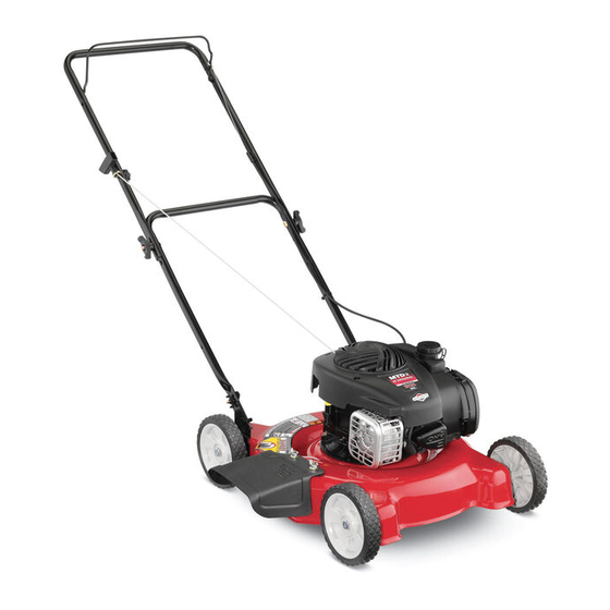
Push mower
Hide thumbs
Also See for A00 Series:
- Operator's manual (48 pages) ,
- Operator's manual (41 pages) ,
- Operator's manual (44 pages)
Table of Contents
Advertisement
Safe Operation Practices • Set-Up • Operation • Maintenance • Service • Troubleshooting • Warranty
'
operator
s manual
Push Mower — Model Series A00, A10, A20, B00, B10, & B20
WARNING
READ AND FOLLOW ALL SAFETY RULES AND INSTRUCTIONS IN THIS MANUAL
BEFORE ATTEMPTING TO OPERATE THIS MACHINE.
FAILURE TO COMPLY WITH THESE INSTRUCTIONS MAY RESULT IN PERSONAL INJURY.
P. O. Box 1386, 97 Kent Avenue, KITCHENER, ONTARIO, CANADA N2G 4J1
769-08603A
Printed In USA
10.30.13
Advertisement
Chapters
Table of Contents
Troubleshooting

Related Manuals for MTD A00 Series


Summary of Contents for MTD A00 Series
- Page 1 Safe Operation Practices • Set-Up • Operation • Maintenance • Service • Troubleshooting • Warranty ’ operator s manual Push Mower — Model Series A00, A10, A20, B00, B10, & B20 WARNING READ AND FOLLOW ALL SAFETY RULES AND INSTRUCTIONS IN THIS MANUAL BEFORE ATTEMPTING TO OPERATE THIS MACHINE.
-
Page 2: Table Of Contents
Choose from the options below: ◊ Visit our web at www.mtdcanada.ca ◊ Locate your nearest dealer from Customer Support: 1-800-668-1238 ◊ Contact MTD CANADA • P.O. Box 1386 • 97 Kent Avenue • Kitchener, Ontario, Canada • N2G 4J1... -
Page 3: Important Safe Operation Practices
Important Safe Operation Practices WARNING: This symbol points out important safety instructions which, if not followed, could endanger the personal safety and/or property of yourself and others. Read and follow all instructions in this manual before attempting to operate this machine. Failure to comply with these instructions may result in personal injury. - Page 4 A missing or damaged discharge cover can cause blade When starting engine, pull cord slowly until resistance contact or thrown object injuries. is felt, then pull rapidly. Rapid retraction of starter cord (kickback) will pull hand and arm toward engine faster than Many injuries occur as a result of the mower being pulled you can let go.
- Page 5 Service Check the blade and engine mounting bolts at frequent intervals for proper tightness. Also, visually inspect blade Safe Handling Of Gasoline: for damage (e.g., bent, cracked, worn) Replace blade with the original equipment manufacture’s (O.E.M.) blade only, To avoid personal injury or property damage use extreme listed in this manual.
-
Page 6: Spark Arrestor
Notice Regarding Emissions Spark Arrestor Engines which are certified to comply with California and federal WARNING: This machine is equipped with an EPA emission regulations for SORE (Small Off Road Equipment) internal combustion engine and should not be used are certified to operate on regular unleaded gasoline, and on or near any unimproved forest-covered, brush may include the following emission control systems: Engine covered or grass-covered land unless the engine’s... -
Page 7: Safety Symbols
Safety Symbols This page depicts and describes safety symbols that may appear on this product. Read, understand, and follow all instructions on the machine before attempting to assemble and operate. Symbol Description READ THE OPERATOR’S MANUAL(S) Read, understand, and follow all instructions in the manual(s) before attempting to assemble and operate DANGER —... - Page 8 2 — i ection mportant peration racticeS...
-
Page 9: Assembly & Set-Up
Assembly & Set-Up Contents of Carton • One Lawn Mower • One Grass Catcher† • One Bottle of Oil • One Lawn Mower Operator’s Manual • One Engine Operator’s Manual • One Side Discharge Chute† † If Equipped NOTE: The units illustrated may vary slightly from your unit. While stabilizing mower so it doesn’t move, pivot upper handle up as shown in Fig. - Page 10 Remove the T-bolts from the handle brackets as shown in Fig. 3-3. Figure 3-5 The rope guide is attached to the right side of the upper Figure 3-3 handle. Loosen the wing knob which secures the rope guide. See Fig. 3-6. Follow the steps below to complete handle assembly: Hold blade control against upper handle.
- Page 11 Side Discharge Chute (If Equipped) Slip plastic channel of grass bag over hooks on the frame. See Fig. 3-7. Your mower may be shipped as a mulcher. To convert to side discharge, make sure grass catcher (if equipped) is off of the unit and rear discharge door (if equipped) is closed.
- Page 12 Adjustments Handle Pitch (If Equipped) For convenience of operation, you may be able to adjust the Cutting Height pitch of the handle as follows: There is a cutting height adjustment lever located above the Remove wing nuts and carriage bolts from handle. See Fig. front and rear right wheel.
-
Page 13: Controls And Features
Controls and Features Blade Control Recoil Starter Grass Catcher† Cutting Height Adjustment Lever Cutting Height Side Discharge Adjustment Chute† Lever Mulch Plug† † If Equipped Figure 4-1 Blade Control Mulch Plug (If Equipped) The blade control is attached to the upper handle of the mower. The mulch plug is used for mulching purposes. -
Page 14: Operation
Operation Starting & Stopping Engine Using Grass Catcher (If Equipped) Refer to the Engine Operator’s manual packed with your lawn You can use the grass catcher to collect clippings while you are mower for instructions on starting and stopping the engine. operating the mower. -
Page 15: Maintenance & Adjustment
Maintenance & Adjustments Maintenance If your mower is equipped with ball bearing wheels, lubricate at least once a season with a light oil, all other General Recommendations types require no lubrication. However, if the wheels are removed for any reason, lubricate the surface of the Always observe safety rules when performing any axle bolt and the inner surface of the wheel with light maintenance. - Page 16 Engine Deck Wash (If Equipped) Refer to the separate engine manual for engine Your mower’s deck may be equipped with a water port on its maintenance instructions. surface as part of its deck wash system. Maintain engine oil as instructed in the separate engine Use the deck wash to rinse grass clippings from the deck’s manual packed with your unit.
-
Page 17: Service
Service Blade Care Lubricate the engine crankshaft and the inner surface of the blade adapter with light oil. Slide the blade adapter WARNING: When removing the cutting blade for onto the engine crankshaft. Place the blade on the adapter sharpening or replacement, protect your hands with such that the side of the blade marked “Bottom”... -
Page 18: Troubleshooting
Troubleshooting Problem Cause Remedy Engine Fails to start 1. Blade control disengaged. 1. Engage blade control. 2. Spark plug boot disconnected. 2. Connect wire to spark boot. 3. Fuel tank empty or stale fuel. 3. Fill tank with clean, fresh gasoline. 4. -
Page 19: Replacement Parts
Replacement Parts Component Part Number and Description 734-04063A Wheel (Front - 7”, Star Diamond) 734-04562 Wheel (Front - 7” x 1.8”, SL:Pin Bar) 734-1988 Wheel (Front - 7” x 1.8”, SL:Spoke Bar) 734-04063A Wheel (Rear - 7”, Star Diamond) 734-04563 Wheel (Rear - 8”... -
Page 20: Warranty
HOW TO OBTAIN SERVICE: Warranty service is available, WITH PROOF OF PURCHASE, through your local authorized service dealer. To locate the dealer in your area contact MTD Products Limited, Kitchener, ON N2G 4J1, or call 1-800-668-1238 or log on to our Web site at www.mtdcanada.com. - Page 21 READ AND FOLLOW ALL SAFETY RULES AND INSTRUCTIONS IN THIS MANUAL BEFORE ATTEMPTING TO OPERATE THIS MACHINE. FAILURE TO COMPLY WITH THESE INSTRUCTIONS MAY RESULT IN PERSONAL INJURY. MTD Products Ltd., P. O. Box 1386, KITCHENER, ONTARIO N2G 4J1 Printed In USA 769-09442A...
- Page 22 To The Owner Thank You This Operator’s Manual is an important part of your new engine. It will help you prepare and maintain the engine for the best performance. Please read and understand the contents before operating the engine. Table of Contents Safe Operation Practices ........
-
Page 23: Safe Operation Practices
Important Safe Operation Practices WARNING! This symbol points out important safety instructions which, if not followed, could endanger the personal safety and/or property of yourself and others. Read and follow all instructions in this manual before attempting to operate the equipment. Failure to comply with these instructions may result in personal injury. - Page 24 Maintenance & Storage Do not overfill fuel tank. Fill tank to full as indicated by the fuel level indicator installed inside of the fuel tank. Do not Keep the engine in safe working order over-fill to allow space for fuel expansion. On some models, a fuel level indicator may NOT be present, in this instance, Allow the engine to cool at least five minutes before fill the tank no more than 1/2 inch below the bottom of the...
- Page 25 Safety Symbols This page depicts and describes safety symbols that may appear on this product. Read, understand, and follow all instructions on the machine before attempting to assemble and operate. Symbol Description READ THE OPERATOR’S MANUAL(S) Read, understand, and follow all instructions in the manual(s) before attempting to assemble and operate WARNING—GASOLINE IS FLAMMABLE Allow the engine to cool at least two minutes before refueling.
-
Page 26: Set-Up
Set-Up Gas & Oil Checking Oil Level IMPORTANT: Be sure to check the oil while on a level surface with NOTE: The engine is shipped without gasoline or oil in the the engine stopped. engine. Running the engine with insufficient oil can cause serious engine damage and void the engine warranty. - Page 27 Extended Dipstick Fuel Requirements Remove the oil filler cap and wipe the dipstick clean. See CAUTION: Operating the engine with E15 or E85 Figure 3-3. fuel, an oil/gasoline mixture, dirty gasoline, or gasoline over 30 days old without fuel stabilizing additive may result in damage to your engine’s carburetor.
-
Page 28: Controls & Features
Controls and Features Fuel Cap Primer† Starter Handle Air Cleaner Oil Fill Cap Oil Drain Spark Plug † If Equipped Muffler Figure 4-1 Primer Fuel Cap (If Equipped) The primer is located on the left side of the Remove the fuel cap to add fuel. engine, next to the air cleaner. -
Page 29: Operation
Operation Pre-Operation Check The engine is shipped without gasoline or oil in the engine. See the Set-Up Section of this manual for instructions on adding oil and gasoline. Determine The Starting System Before starting the engine, you must determine the type of starting system that is on your engine. -
Page 30: Engine Maintenance
Engine Maintenance WARNING: Periodic inspection and adjustment of the engine is essential if Shut off the engine before performing high level performance is to be maintained. Regular maintenance any maintenance. To prevent accidental start-up, will also ensure a long service life. The required service intervals disconnect the spark plug boot. -
Page 31: Air Filter Service
Oil Service Air Filter Service • Check oil level regularly. WARNING: Never use gasoline or low flash point solvents for cleaning the air filter element. A fire or • Be sure correct oil level is maintained. Check every five explosion could result. hours or daily before starting engine. - Page 32 Paper Filter WARNING: If the engine has been running, the muffler will be very hot. Be careful not to touch the Remove the air filter cover by turning counter-clockwise muffler. then pulling it towards you. See Figure 6-3. NOTE: Paper filters cannot be cleaned and must be Visually inspect the spark plug.
-
Page 33: Removing From Storage
Fuel Filter Service Storage The fuel filter cannot be cleaned and must be replaced once a CAUTION: Failure to use a fuel stabilizing additive year or every 100 operating hours; more often if run with old such as STA-BIL® or completely run the engine until gasoline. -
Page 34: Troubleshooting
Troubleshooting Problem Cause Remedy Engine Fails to start 1. Blade control disengaged. 1. Engage blade control. 2. Spark plug boot disconnected. 2. Connect wire to spark boot. 3. Fuel tank empty or stale fuel. 3. Fill tank with clean, fresh gasoline. 4. -
Page 35: Replacement Parts
Replacement Parts Component Part Number and Description 951-14437 Spark Plug 951-14627 Air Cleaner (Foam) 951-14628 Air Cleaner (Paper) 951-12738 Fuel Cap Assembly 951-10358A Fuel Filter NOTE: Download a complete Parts Manual, refer to customer support on page 2. Be sure to have your model number and serial number ready. - Page 36 Any warranted part that is not scheduled for replacement as required maintenance in the written instructions supplied is warranted for the warranty period stated above. If the part fails during the period of warranty coverage, the part will be repaired or replaced by MTD Consumer Group Inc according to subsection (4) below.
- Page 37 NOTE: If you require warranty service in Canada and your product was sold by MTD Products Limited within Canada to the retailer you purchased it from in Canada then the MTD Consumer Group Inc portion of this warranty will be honored by MTD Products Limited in Canada.
- Page 38 Notes...
- Page 39 ’ NOTICE D UTILISATION A00, A10, A20, B00, B10, & B20 Tondeuse poussée – Modèles/Séries AVERTISSEMENT PRIÈRE DE LIRE TOUTES LES INSTRUCTIONS FIGURANT DANS CETTE NOTICE D’UTILISATION AVANT D’ESSAYER DE VOUS SERVIR DE CETTE MACHINE. LE NON-RESPECT DE CES INSTRUCTIONS PEUT ENTRAÎNER DES BLESSURES CORPORELLES.
- Page 40 À l’intention du propriétaire Merci ! Merci d’avoir acheté votre nouvel équipement. Celui-ci véhicule ne pas s’appliquer à tous les modèles. Le fabricant se réserve le a été soigneusement conçu pour vous offrir des performances droit de modifier les caractéristiques techniques du produit, les remarquables s’il est correctement utilisé...
-
Page 41: Consignes De Sécurité
Importantes consignes de sécurité AVERTISSEMENT: Ce symbole attire votre attention sur des consignes de sécurité importantes qui, si elles ne sont pas respectées, peuvent mettre en danger non seulement votre personne et d’utilisation avant d’essayer de vous servir de cette machine. Le non-respect de ces instructions AVERTISSEMENT: Les gaz d’échappement de ce produit contiennent des produits chimiques reconnus dans l’État de Californie comme causant le cancer, des anomalies congénitales ou d’autres problèmes liés à... - Page 42 faire reculer la tondeuse près d’un mur d’un autre obstacle, du démarreur à lanceur jusqu’à ce que vous sentiez une regardez d’abord par terre et derrière vous, puis procédez légère résistance, puis tirez-la rapidement. Le retour rapide comme suit: de la corde du démarreur (le recul) attirera votre main et votre bras vers le moteur plus vite que vous ne pourrez lâcher a.
- Page 43 sons, d’autres objets qui peuvent gêner votre visibilité. avant de la remiser. 5. Éloignez les enfants des moteurs chauds ou en cours Entretien général: d’utilisation. Les enfants peuvent subir des brûlures graves au 1. Ne faites jamais fonctioner la machine dans un local clos car plus doivent lire la notice d’utilisation, bien comprendre le vérifiez que la lame et toutes les pièces mobiles se sont fonctionnement de la machine et respecter les consignes de...
- Page 44 Avis concernant les émissions de gaz Commission sur la sécurité des produits de consommation) américaine de protection de l’environnement), ce produit a équipement hors route) sont certifiés pour fonctionner avec de l’essence sans plomb ordinaire et peuvent être dotés des systèmes de contrôle des émissions de gaz suivants : Engine moyenne, achetez une machine neuve ou faites inspecter Modification (EM) et Three Way Catalyst (TWC) le cas échéant.
- Page 45 Symboles de sécurité instructions sur la machine et vous assurer de bien les comprendre avant d’essayer d’assembler et d’utiliser la machine. Symbol Description Veuillez lire et suivre toutes les instructions sur la machine et vous assurer de bien les comprendre avant d’essayer d’assembler et d’utiliser la machine. mouvement.
- Page 46 2 — I ECTION MPORTANTES CONSIGNES DE SÉCURITÉ...
-
Page 47: Assemblage Et Montage
Assemblage et Montage Pièces détachées dans le carton • Un tondeuse • Un sac à herbe † • Un bidon d’huile • Une notice d’utilisation de la tondeuse • Une notice d’utilisation du moteur • Une goulotte d’éjection latérale † †... - Page 48 Retirez les boulons à tête en T des supports du guidon, comme la Figure 3-3. Figure 3-5 Figure 3-3 du guidon supérieutr. Desserrez le boulon à oreilles qui maintient le guide de la corde en place. Voir la Figure 3-6. Suivez les instructions ci-dessous pour terminer Tenez la commande de la lame contre le guidon l’assemblage du guidon .
- Page 49 Sac à herbe (les cas écheant) de la tondeuse. Relevez le sac à herbe et dégagez-le des fentes des supports du guidon. Lâchez le clapet d’éjection arrière pour tondeuse s’il n’est pas déjà installé. Vérifiez que le sac à fermer l’ouverture sur l’arrière de la tondeuse. herbe est bien à...
- Page 50 IMPORTANT: Les roues avant et arrière doivent être réglées à la Réglages placez le levier à une hauteur plus élevée. Vous éviterez ainsi Hauteur de coupe d’arracher l’herbe. La manette de réglage de la hauteur de coupe se trouve au- dessus des roues avant et arrière droites.
-
Page 51: Commandes Et Caractéristiques
Commandes et caractéristiques Commande de la lame Démarreur à lanceur Sac à herbe † Levier de réglage de la hauteur de coupe Levier de réglage de la hauteur de coupe Goulotte d’éjection latérale † Bouchon de déchiquetage † † Le cas échéant Figure 4-1 Commande de la lame Bouchon de déchiquetage (le cas écheant) - Page 52 Utilisation Mise en marche et arrêt du moteur Emploi du sac à herbe (les cas écheant) Consultez la notice d’utilisateur du moteur emballé avec votre Vous pouvez utiliser le sac à herbe pour ramasser l’herbe coupée tondeuse pour des instructions concernant la mise en marche et pendant que vous travaillez.
-
Page 53: Entretien Et Réglages
Entretien & Réglages Entretien Lubrifiez les roulements à billes (s’il en est) des roues au moins une fois par saison avec de l’huile fluide. Tous les Recommandations d’ordre général autres types de roues n’ont pas besoin d’être lubrifiées. Toutefois, si les roues doivent être démontées pour une Suivez toujours les consignes de sécurité... - Page 54 Moteur Système de nettoyage du plateau de coupe (le cas Consultez la notice d’utilisation du moteur pour tout ce qui échéant) concerne l’entretien du moteur. Un orifice à eau est incorporé au plateau de coupe de cette Utilisez l’huile à moteur recommandée dans la notice tondeuse et fait partie du système de nettoyage de celui-ci.
- Page 55 Service Entretien et remplacement de la lame Lubrifiez le vilebrequin et la surface intérieure de AVERTISSEMENT : En enlevant la lame ou la l’adaptateur de la lame sur le vilebrequin et positionnez la courroie, portez toujours des gants épais ou utilisez le numéro de pièce) se trouve sur le dessous (vers le sol) un chiffon épais pour tenir la lame.
-
Page 56: Dépannage
Dépannage Problème Cause Solution Le moteur ne 1. La poignée de commande de la lame 1. Embrayez la commande de la lame. n’est pas embrayée. démarre pas. 2. Fil de la bougie débranché. 3. Le réservoir est vide ou l’essence est éventée. 3. -
Page 57: Pièces De Rechange
Pièces de rechange Pièce No. de pièce et description 734-04063A Roue (avant) - 7 po, Star Diamond 734-04562 Roue (avant) - 7 po x 1,8 po, barrettes 734-1988 Roue (avant) - 7 po x 1,8 po, SL:Spoke Bar 734-04063A Roue (arrière) - 7 po, Star Diamond 734-04563 Roue (arrière) - 8 po x 1,8 po, barrettes 634-04625... -
Page 58: Garantie
à la disposition du client. Les stipulations énoncées dans cette garantie offrent le seul recours à la suite de la vente. MTD ne peut être tenue responsable pour toute perte ou tout dommage accessoire ou immatériel comprenant, sans s’y limiter, les frais de remplacement ou de substitution des services d’entretien des pelouses ou les frais de location pour remplacer...
Need help?
Do you have a question about the A00 Series and is the answer not in the manual?
Questions and answers