
Related Manuals for MicroNet SP3501AM


Summary of Contents for MicroNet SP3501AM
- Page 1 User’s Manual VDSL CO / CPE Modem Model No.: SP3501AM/SP3501AS http://www.micronet.info...
-
Page 2: Table Of Contents
Table of Contents Chapter 1 Introduction................. 1 1.1 Package Contents ................1 1.2 Key Features ..................1 Chapter 2 Installation................... 3 2.1 Hardware Installation................ 3 2.2 Pre-installation Requirements ............3 2.3 Cabling Requirements..............3 2.4 Connecting the Modem ..............4 2.5 Connecting the RJ-11/RJ-45 Ports........... -
Page 3: Chapter 1 Introduction
Chapter 1 Introduction Micronet SP3501AM / SP3501AS delivers cost-effective and high- performance broadband access to multiunit building environments, such as enterprise, campus, hospital, hotel, and telecom. With QAM-based 4-band VDSL technology, the VDSL solution dramatically extends Ethernet and supports 5M/15M/25Mbps symmetrical bandwidth over existing telephone- grade wiring up to 1.9/1.3/0.8KM. - Page 4 Fixed/Auto speed function for VDSL link Built-in POTS/ISDN splitter (SP3501AM) for POTS/ISDN telephone service...
-
Page 5: Chapter 2 Installation
Chapter 2 Installation Hardware Installation This section describes how to install the Modem and establish network connections. Users may install the Modem on any level surface. However, please take note of the following minimum site requirements. Pre-installation Requirements Prior to the start of actual hardware installation, make sure users can provide the right operating environment, including power requirements, sufficient physical space, and proximity to other network devices that are to be connected. -
Page 6: Connecting The Modem
24-26 Gauge phone wiring 5M/5M: 1.9km VDSL Port (RJ-11) Do not recommend 28 or 15M/15M: 1.3km above Gauge 25M/M: 800m Connecting the Modem The Modem provides a single Ethernet port, which support connection through Ethernet operation. Network devices attached to the Ethernet port must support auto- negotiation, 10Base-T or 100Base-TX. - Page 7 1.9km or 800m (depend on speed) between the two farthest points. SP3501AM/S Modem has embedded Splitter between every VDSL side (Line) and POTS (Phone) side. It permits user to deliver broadband service on the same lines as Plain Old Telephone Service (POTS), PBX, ISDN traffic and VDSL Signal.
-
Page 8: Chapter 3 Physical Description
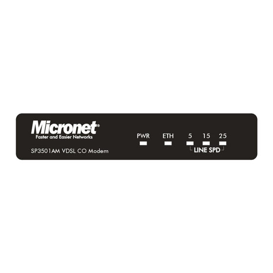
Chapter 3 Physical Description SP3501AM/SP3501AS front view SP3501AM/SP3501AS rear view LED Definition Status Operation Steady Green Device is powering on or reset ok (Power LED) Lights up steadily to show good Steady Green linkage (Ethernet LED) Flashing Green Flashing to show data transmission... -
Page 9: Chapter 4 Speed Configuration
Chapter 4 Speed Configuration Fixed/Auto Speed Function SP3501AM/S is a 4-band VDSL solution which supports auto and manual speed function and real plug & play. It can support 5M/15M/25M symmetrical data service depend on installation environment. If the cable length is unsure, then auto selection of the data speed at the default setting is recommended. -
Page 10: Speed Mode Limitation
Table shows the summary of DIP switch configuration. DIP Switch Configuration Note: 1. Don’t switch on or off all pins as it will make the VDSL modem functionless. 2. Before selecting the data speed, the power must be turned off for safety purposes. -
Page 11: Chapter 5 Appendix
Chapter 5 Appendix Cable Requirements A CAT 3, 4 or 5 UTP (unshielded twisted pair) cable is typically used to connect the Ethernet device to the Modem. A 10Base-T cable often consists of four pairs of wires, two of which are used for transmission. The connector at the end of the 10Base-T cable is referred to as an RJ-45 connector and it consists of eight pins. - Page 12 it consists of six pins. POTS (plain old telephone services) use pins 3 and 4 for voice transmission. A telephone cable is shown below. The A and B connectors on the rear of the Modem are RJ-11 connectors. These connectors are wired identically. The RJ-11 connectors have six positions, two of which are wired .The Modem uses the center two pins and the pin out assignment for these connectors is presented below.
-
Page 13: Specifications
Compatibility with xDSL, ISDN (2B1Q/4B3T). Surge protection Long packet size up to 1536 bytes Auto MDI/MDIX and auto negotiation on Ethernet port Fixed/Auto speed function and full duplex on VDSL port Built-in splitter (SP3501AM) UPnP VDSL Frequency SP3501AM: Spectrum Transmitter: 900 KHz ~ 3.9MHz Receiver: 4MHz &... -
Page 14: Troubleshooting
Verify the cables are connected properly on both ends. Verify the proper cable is used and the distant does not exceed the specified limit. Phone wire must be connected between SP3501AM and SP3501AS prior to powering on of devices. Replace the defective cable or modem if necessary. -
Page 15: Other Issues
Symptom: S0 bus from an NTBA - data works, but ISDN telephone does not. Solution: Connect according to the following chart for connecting CO and CPE with NTBA. Other Issues Power and Cooling Problems If the POWER indicator does not turn on when the power cord is plugged in, users may have a problem with the power outlet, power cord, or internal power supply as explained in the previous section. - Page 16 Transmission Mode The default method of selecting the transmission mode for RJ-45 port is 10/100 Mbps and for RJ-11 port is 5/15/25Mbps. Therefore, if the link signal is disrupted (e.g., by unplugging the network cable and plugging it back in again, or by resetting the power), the port will try to establish communications with the attached device via auto-negotiation.
Need help?
Do you have a question about the SP3501AM and is the answer not in the manual?
Questions and answers