Table of Contents
Advertisement
Quick Links
Advertisement
Table of Contents

Related Manuals for MicroNet SP3501C


Summary of Contents for MicroNet SP3501C
- Page 1 User’s Manual VDSL2 CO/CPE Modem Model: SP3501C...
-
Page 2: Table Of Contents
Table of contents 1. Introduction ......................1 1.1 Package Contents ..................1 1.2 Features ....................1 2. Installation ......................2 2.1 Hardware Installation ................2 2.2 Pre-installation Requirements ..............2 2.3 General Rules ................... 2 2.4 Connecting the VDSL2 Modem ..............3 3. -
Page 3: Introduction
VDSL2 technology, to carriers and MxU (Multi-Dwelling/Multi-Tenant Units) environments that need for new services such as IPTV, video conferencing, VoIP, peer-to-peer file sharing, and interactive gaming. Micronet SP3501C VDSL2 CO / CPE Modem are fully compliant with ITU-T G.993.2 VDSL2 standard also supports... -
Page 4: Installation
Support auto speed for Line port and Interleave mode selectable through CO side DIP switch DIP switch with CO and CPE mode selectable Supports long packet size up to 1536 bytes Supports Surge protection Supports wall mounting ... -
Page 5: Connecting The Vdsl2 Modem
Category 3, 4 UTP for 10Mbps No more than 100 meters of cabling may be use between the MUX or HUB and an end node. Phone Port (RJ-11) All Phone set connections to the RJ-11 Port made using 24~26 Gauge phone wiring. - Page 6 Do not plug a RJ-11 phone jack connector into the Ethernet port (RJ-45 port). This may damage the modem. Instead, use only twisted-pair cables with RJ-45 connectors that conform to Ethernet standard. Step 2. RJ-45 connection The Modem provides 2 Ethernet port, which support connection through Ethernet operation.
-
Page 7: Hardware Description
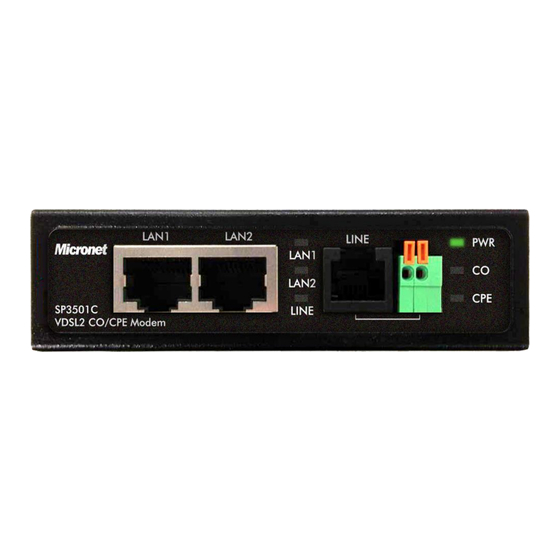
3. Hardware Description This section describes the important parts of the VDSL2 Modem. It features the front indicators and rear connectors. 3.1 Front Panel The following figure shows the front panel. Figure 3.1 Front Panel Tip: At a quick glance of the front panel, it is easy to determine if it has Ethernet signal from its RJ-45 port and if there is vdsl line signal on RJ-11 port. -
Page 8: Rear Panel
CO (Local Side) Indicate the VDSL2 modem is running at CO(Master) Green On(Steady) (CO LED) mode. CPE (Remote Side) Indicate the VDSL2 modem is running at CPE(Slave) Green On(Steady) (CPE LED) mode. On(Steady) The Internet or network connection is up. Blinking slowly The CO device is auto-detecting CPE device. -
Page 9: Dip Switch
3.4 DIP switch The following figure shows the DIP switch connection. By switching the transmission modes, you can obtain a best transmission mode to suit with phone line quality or distance or connectivity. DIP switch setting The following is table of DIP Switch configuration. (Table 3-4) Table 3-4 DIP Switch Configuration... - Page 10 When SNR margin is selected, the system provide 6db/9db SNR margin for across all usable loop length. Please note that the 6db SNR margin is for telecom standard. Generally speaking, the higher SNR value gets better line quality, but lower performance.
- Page 11 INP(Impulse Noise Protection): Impulse noise in multicarrier communication systems behaves effectively as a modulating signal that controls the first moment of the background Gaussian noise. The composite noise, which is the aggregate of the Gaussian noise and impulse noise, has a probability density function that is conditionally Gaussian with non-zero average, hence referred to as biased-Gaussian.
- Page 12 Use separate paths to route wiring for power and devices. If power wiring and device wiring paths must cross, make sure the wires are perpendicular at the intersection point. Note: Do not run signal or communications wiring and power wiring through the same wire conduit.
-
Page 13: Appendix A: Cable Requirements
Appendix A: Cable Requirements Ethernet Cable A CAT 3~7 UTP (unshielded twisted pair) cable is typically used to connect the Ethernet device to the modem. A 10Base-T cable often consists of four pairs of wires, two of which are used for transmission. The connector at the end of the 10Base-T cable is referred to as an RJ-45 connector and it consists of eight pins. - Page 14 Figure A-2 Pin Assignments and Wiring for an RJ-45 Straight-Through Cable Pin Assignments and Wiring for an RJ-45 Crossover Cable...
-
Page 15: Appendix B: Product Specification
Appendix B: Product Specification Model SP3501C Standards IEEE802.3 10BASE-T, IEEE802.3u 100BASE-TX ITU-T G993.2 Interface 2 x RJ-45 10/100Mbps Ethernet ports 1 x RJ-11 connector for EoVDSL 1 x DIP Switch 1 x Power Jack ... -
Page 16: Appendix C: Troubleshooting
Appendix C: Troubleshooting 1. Symptom: POWER indicator does not light up (green) after power on. Cause: Defective External power supply Check the power plug by plugging in another that is functioning properly. Check the power cord with another device. If these measures fail to Solution: resolve the problem, have the unit power supply replaced by a qualified distributor. - Page 17 Very-high-speed digital subscriber line 2 (VDSL2) is an access technology that exploits the existing infrastructure of copper wires that were originally deployed for traditional telephone service. It can be deployed from central offices, from fiber-optic connected cabinets located near the customer premises, or within buildings. It was defined in standard ITU-T G.993.2 finalized in 2005.
- Page 18 and eliminate the source of noise. Connected the CO Modem with CPE Modem within 300 meters 6. Problem: RJ-11 phonecable got only less than 10 Mbit/s. Some testing program that is base on TCP/IP protocol such as FTP, Iperf, NetIQ, and the bandwidth of testing outcome will be Cause: limited by TCP window size.
-
Page 19: Appendix D : Compliance And Safety Information
Appendix D : Compliance and Safety Information FCC Radio Frequency Interference Statement This equipment has been tested to comply with the limits for a computing device, pursuant to Part 15 of FCC rules. These limits are designed to provide reasonable protection against harmful interference when the equipment is operated in a commercial environment. - Page 20 Do not use this equipment near water, for example in a wet basement. Avoid using a telephone during an electrical storm. There may be a remote risk of electrical shock from lightning. Do not use the telephone to report a gas leak in the vicinity of the leaking area.
-
Page 21: Safety Warnings
VDSL2 deteriorates quickly from a theoretical maximum of 200 Mbit/s (Full-Duplex) at 'source' to 100 Mbit/s at 0.3 km (symmetric). Safety Warnings For your safety, be sure to read and follow all warning notices and instructions before device use. DO NOT open the device or unit. Opening or removing covers can expose you to dangerous high voltage points or other risks. -
Page 22: Ce Mark Warning
frequency energy and, if not installed and used in accordance with the instruction manual, may cause harmful interference to radio communications. Operation of this equipment in a residential area is likely to cause harmful interference in which case the user will be required to correct the interference at owner’s expense. CE Mark Warning This is a CE class A product.
Need help?
Do you have a question about the SP3501C and is the answer not in the manual?
Questions and answers