
Related Manuals for DeLonghi AWR-MTD2-XE


Summary of Contents for DeLonghi AWR-MTD2-XE
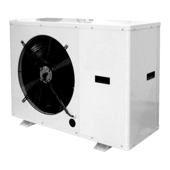
- Page 1 INSTALLATION - OPERATING - SERVICE MANUAL Reverse-cycle air/water heat pumps with domestic hot water production, axial-flow fans and water pump assembly. AWR-MTD2-XE 0011÷0091...
- Page 2 The following symbols are used in this publication and inside the unit: User Important Danger high temperatures Installer Prohibition Assistance Danger voltage Eurovent certification program. The manufacturer reserves the right to modify the data in this manual without warning. AWR-MTD2-XE EN 11/2010...
- Page 3 (cardboard, staples, plastic Handle the unit with the utmost care (see weight distrib- bags, etc.) as they may represent a hazard. ution table) to avoid damage. EN 11/2010 AWR-MTD2-XE...
- Page 4 • probe BT9 only to be installed when supplementary The instruction manual is an integral part of the unit source is available and should therefore be read and kept carefully. Make sure the components listed above are not lost or mis- placed. AWR-MTD2-XE EN 11/2010...
- Page 5 NOMENCLATURE AWR MTD2 XE 0011 s = peak limiter Power supply voltage: m = 230V/50Hz/1ph t = 400V/3N/50Hz size Model EN 11/2010 AWR-MTD2-XE...
- Page 6 17 Safety valve 18 Air vent valve 19 Pressure gauge 20 Base electric heater 21 Pressure transducer VERSIONS AVAILABLE AWR-MTD2-XE Reverse-cycle air/water heat pump with domestic hot water production. Built-in water pump assem- bly without electric heaters. AWR-MTD2-XE EN 11/2010...
- Page 7 • poor air change or people. • stratification of air • If the outside air temperature is less than 0°C, the conden- sate may freeze; in these case fit a frost protection heater on the drain line. EN 11/2010 AWR-MTD2-XE...
- Page 8 (both on the system circuit and domestic erwise install an additional expansion vessel. hot water circuit). AWR-MTD2-XE EN 11/2010...
- Page 9 0,86 x 10 0,96 0,99 0,99 mance tables by the coefficient given in the following table. 1,72 x10 0,93 0,98 0,98 f1: capacity correction factor fk1: compressor power input correction factor fx1: total power input correction factor EN 11/2010 AWR-MTD2-XE...
- Page 10 - Start filling by slowly opening the system water fill valve out- if it drops below 1 bar, the water content should be side the unit. topped-up. - When water begins to leak out of the terminal air vent valves, Check the tightness of the joints. AWR-MTD2-XE EN 11/2010...
- Page 11 0051t 400-3N-50 6,43 12,7 1,25 0061t 400-3N-50 7,77 14,8 1,25 0091t 400-3N-50 10,86 24,6 1,25 F.L.I. Maximum power input F.L.A. Maximum current input L.R.A. Start-up current Maximum values for sizing the protection switches and power supply cables. EN 11/2010 AWR-MTD2-XE...
-
Page 12: Power Supply
5 6 7 8 9 10 11 12 13 14 15 16 17 18 19 20 21 22 23 24 25 26 27 28 29 30 31 32 33 34 35 36 37 38 39 40 41 42 43 44 45 46 47 48 49 50 51 52 53 54 55 INSTALLER TERMINAL BLOCK AWR-MTD2-XE EN 11/2010... - Page 13 “init” is shown and the clock is displayed Power supply 230V 400V Number of power wires 2 + PE 4 + PE Power wire size* 6 mmq 6 mmq * Compliant with standards in force in the place where the unit is installed EN 11/2010 AWR-MTD2-XE...
- Page 14 • Re-place the cover of the sensor. TECHNICAL DATA (25°C) Sensing element NTC 10Kohm ± 1% BT11 Degree of protection IP65 Perm. ambient / carriage temperature -50°C...+100°C Measuring range -50°C...+100°C Materials PA 15% GK, Colour RAL 9010 45 46 AWR-MTD2-XE EN 11/2010...
- Page 15 • Make the electrical connections as shown in the figure (6), also see the wiring diagram. 83,5 A5 room controller terminal block Installer terminal block 51 52 53 54 55 Number of wires 5 shielded Power supply wire size 0.5 mm Maximum distance 500 m EN 11/2010 AWR-MTD2-XE...
- Page 16 An electric heater installed at the outlet can be activated as a supplementary heater for the system. 230V / 400V Solution 1 System with heat pump and electric heater with storage tank. Position probe BT9 in the storage tank. AWR-MTD2-XE EN 11/2010...
- Page 17 Integration time to activate outlet elec- Mn06 0617 °C*sec tric heaters Set the parameters following the sequence described in the table EN 11/2010 AWR-MTD2-XE...
- Page 18 Actual temperature = 40°C (50 – 40) x 60 sec = 600°Csec. ----> Electric heater ON Low values of 0617 mean frequent activation of the heater. Too high values of 0617 mean long delays in activating the heater AWR-MTD2-XE EN 11/2010...
- Page 19 0618 min. the heat pump to reach steady operation and thus avoid activat- ing the boiler when not needed) Integration time to activate boiler Mn06 0619 °C*sec Set the parameters following the sequence described in the table EN 11/2010 AWR-MTD2-XE...
- Page 20 Actual temperature = 40°C (50 – 40) x 60 sec = 600°Csec. ----> Boiler ON Low values of 0619 mean frequent activation of the boiler. Too high values of 0619 mean long delays in activating the boiler AWR-MTD2-XE EN 11/2010...
- Page 21 SATURDAY (0=no; 1=yes) Legionella prevention cycle day Mn02 0220 SUNDAY (0=no; 1=yes) Legionella prevention cycle time Mn02 0221 Enable Legionella prevention Mn02 0222 function 0 = Not enabled 1 = Enabled Maximum Legionella prevention Mn02 0225 min. function duration EN 11/2010 AWR-MTD2-XE...
- Page 22 0172. Configure the contact, selecting the desired function by set- 21 22 ting parameter 015A: Description Menu Parameter Value to be Enable the contact as: Mn01 015A 0= Alarm signal 1= Dehumidifier 3= Secondary circuit pump AWR-MTD2-XE EN 11/2010...
- Page 23 Contact closed = Domestic hot water only Contact open = Domestic hot water + System Set the following parameters: Description Menu Parameter Value to be Enable remote contact Mn01 0100 0= remote contact enabled 1= remote contact disabled (selection from keypad only) EN 11/2010 AWR-MTD2-XE...
- Page 24 During operation at reduced electricity rate, contact closed, the domestic hot water set point is 50°C, as shown in the example, with the contact open it’s 47°C. This allows operation at a higher temperature, within the unit’s operating limits, exploiting the lower electricity cost. AWR-MTD2-XE EN 11/2010...
- Page 25 INSTALLER CONNECTIONS F3 System flow switch System flow switch connection, compulsory component. 39 40 BT8 Domestic hot water storage temperature probe The domestic hot water temperature inside the storage tank is measured using probe BT8 41 42 EN 11/2010 AWR-MTD2-XE...
- Page 26 INSTALLER CONNECTIONS ELECTRICAL PANEL LAYOUT AWR-MTD2-XE 0011÷0041 SINGLE-PHASE Radio interference suppresser Controller protection fuse Peak limiter Autotransformer Electronic controller Compressor control relay Fan control module Outlet heater or boiler relay Electric heater actuator Alarm/secondary pump/dehumidifier relay Compressor start capacitor KA15...
- Page 27 INSTALLER CONNECTIONS ELECTRICAL PANEL LAYOUT AWR-MTD2-XE 0031÷0051 THREE-PHASE Radio interference suppresser Phase sequence control relay Electronic controller Outlet heater or boiler relay Fan control module Alarm/secondary pump/dehumidifier relay Electric heater actuator KA15 High pressure switch relay C2-3 Fan start capacitor...
- Page 28 INSTALLER CONNECTIONS ELECTRICAL PANEL LAYOUT AWR-MTD2-XE 0061 AND 0091 THREE-PHASE C90051689E _00 Radio interference suppresser Auxiliary circuit protection fuse Compressor contact Electronic controller Controller protection fuse Compressor circuit breaker Fan control module Autotransformer Door interlock disconnect switch Electric heater actuator...
- Page 29 INSTALLER CONNECTIONS SINGLE-PHASE WIRING DIAGRAM AWR-MTD2-XE 0011÷0041 EN 11/2010 AWR-MTD2-XE...
- Page 30 INSTALLER CONNECTIONS THREE-PHASE WIRING DIAGRAM AWR-MTD2-XE 0031÷0051 AWR-MTD2-XE EN 11/2010...
- Page 31 INSTALLER CONNECTIONS THREE-PHASE WIRING DIAGRAM AWR-MTD2-XE 0061÷0091 EN 11/2010 AWR-MTD2-XE...
- Page 32 (5) Water in-out 12/7°C (plant side), outdoor air temperature 35°C b.s. (6) Sound power level according to ISO 9614 and Eurovent 8/1 (7) Average sound pressure level above one reflecting surface (Q=2) at 1 meter from the outside dimensions of the unit. AWR-MTD2-XE EN 11/2010...
- Page 33 OPERATING LIMITS U I A HEATING Outlet water temperature (°C) COOLING Outlet water temperature (°C) Water temperature head min/max= 3/8 °C Water circuit pressure min/max = 1/3 bar Maximum glycol percentage = 40% EN 11/2010 AWR-MTD2-XE...
- Page 34 Curve 1 Water flow-rate [m AWR MTD2 XE 41 ms - AWR MTD2 XE 41 t Curve 4 Curve 3 Curve 2 Curve 1 Water flow-rate [m The pressure head refers to the values at the fittings. AWR-MTD2-XE EN 11/2010...
- Page 35 Curve 4 Curve 3 Curve 2 Curve 1 Water flow-rate [m AWR MTD2 XE 91 t Curve 4 Curve 3 Curve 2 Curve 1 Water flow-rate [m The pressure head refers to the values at the fittings. EN 11/2010 AWR-MTD2-XE...
- Page 36 (if featured). • Make sure the “A5” room controller is off. • Position the main unit switch QS1 in the ON position, Fig. • Move switch QF1 (outside the unit) to “ON”, Fig. 3. AWR-MTD2-XE EN 11/2010...
- Page 37 • Select the required operating mode by pressing button 5 mode • Select the required room temperature by turning knob 4 For further information on the operation and functions of the room controller, see "Operation and functions of the room controller". EN 11/2010 AWR-MTD2-XE...
- Page 38 - flashing: compressor timer, delay Actuator operating - fixed: compressor active Defrost active Fan active Boiler or electric heater active Frost protection active Secondary field Time, menu, parameter number display Active time band On indicates active time band AWR-MTD2-XE EN 11/2010...
- Page 39 During operation of the unit, pressing the knob displays the information described below. Press the knob Room temperature set point Humidity set point Press the knob Press the knob Outside air temperature Domestic hot water set point Room humidity Press the knob Press the knob Press the knob EN 11/2010 AWR-MTD2-XE...
- Page 40 • Press the button to exit. • Turn the knob to select the day** • Main display ** Mon = Lunedi, Tue = Martedi, Wed = Mercoledi, Thu = Giovedi, Fri = Venerdi, Sat = Sabato, Sun = Domenica AWR-MTD2-XE EN 11/2010...
- Page 41 • Turn the knob • Turn the knob to change the room • The display shows the room tem- • The room temperature set point temperature set point perature is displayed • Wait a few seconds for confirmation EN 11/2010 AWR-MTD2-XE...
- Page 42 • Press the knob to confirm • Turn the knob and select parameter 0023 • Press the knob • Turn the knob to select the domestic hot • Press the knob to confirm water set point ➔ AWR-MTD2-XE EN 11/2010...
- Page 43 OPERATION AND FUNCTIONS OF THE ROOM CONTROLLER • Main display • Press the button twice until reaching the main display. EN 11/2010 AWR-MTD2-XE...
- Page 44 • Press the knob to confirm A Turn the knob A Turn the knob A Turn the knob B Press the knob to confirm the B Press the knob to confirm the B Press the knob to confirm hour value minutes value AWR-MTD2-XE EN 11/2010...
- Page 45 Once the time bands have been deacti- vated check that the room set point is • Press the button. • The symbol is no longer displayed at the required value, otherwise turn the • Time band DEACTIVATED knob to select the desired temperature. EN 11/2010 AWR-MTD2-XE...
- Page 46 Mnu11 Serial protocol Mnu12 Procedure for accessing the menu x3 sec. • Main display • Turn the knob and select the password (as • Press the buttons together for 3 sec- shown in the table) onds ➔ AWR-MTD2-XE EN 11/2010...
- Page 47 • The parameter value flashes • Press the knob to confirm • Turn the knob to change the parameter val- • Main display • Press the button twice until reaching the main display Press the button to exit programming mode EN 11/2010 AWR-MTD2-XE...
- Page 48 Compensation curve number zone LT2 Mn01 0189 zone curve may therefore not request a higher value than the one supplied by the system curve. Enable compensation curve zone Mn01 015E 0= Disabled 1= Enabled Compensation curve number zone LT3 Mn01 012A AWR-MTD2-XE EN 11/2010...
- Page 49 MAXIMUM outlet set point limit for Mn01 0196 °C compensation curve in zone LT2 MINIMUM outlet set point limit for Mn01 012F °C compensation curve in zone LT3 MAXIMUM outlet set point limit for Mn01 012G °C compensation curve in zone LT3 EN 11/2010 AWR-MTD2-XE...
- Page 50 012P increasing water outlet temperature set point ZONE LT2 Value parameter 0157 100% UR% Room Value parameter 0172 humidity (RH%) Maximum outlet temperature hys- Mn01 012R °C Value parameter 0187 teresis corresponding to 100% rela- tive humidity AWR-MTD2-XE EN 11/2010...
- Page 51 "water connections", parameter 0143 should be set to 0. EN 11/2010 AWR-MTD2-XE...
- Page 52 0141. Description Menu Parameter Default Outside temperature to enable Mn01 0141 °C Outside air T frost protection 0141 Outside air temperature to enable frost protection AWR-MTD2-XE EN 11/2010...
- Page 53 The parameters required for correct system operation can be set on the A5 room controller supplied with the heat pump. The next few pages are divided into the following sections: Section 1 WATER CIRCUIT DIAGRAM Section 2 WIRING DIAGRAM Section 3 PARAMETER CONFIGURATION EN 11/2010 AWR-MTD2-XE...
- Page 54 If the minimum system content does not reach val- ues shown in this manual, install an additional storage tank on the heat pump return pipe. No system configurations are required. Water circuit diagram Water circuit diagram (not a working drawing) AWR-MTD2-XE EN 11/2010...
- Page 55 Minimum outside temperature corresponding to max. return Mn01 0129 °C temperature (Te1) Minimum return temperature set point limit in cooling mode (Tm2) Mn01 0130 °C Maximum outside temperature corresponding to min. return Mn01 0131 °C temperature (Te2) EN 11/2010 AWR-MTD2-XE...
- Page 56 SYSTEM CONFIGURATION U I A System number 0 Water circuit diagram Water circuit diagram (not a working drawing) AWR-MTD2-XE EN 11/2010...
- Page 57 SYSTEM CONFIGURATION U I A System number 0 Wiring diagram EN 11/2010 AWR-MTD2-XE...
- Page 58 0131 °C temperature (Te2) Contact HL1 configuration, secondary circuit pump Enable contact HL1 HIGH TEMPERATURE ZONE The contact closes and the pump or motor-driven shut-off valve Mn01 015A is activated) * obligatory values for the present configuration AWR-MTD2-XE EN 11/2010...
- Page 59 - parameter 1105= alarm activation month alarm code from Mn11: - parameter 1106= alarm activation year - parameter 1100 = no. of alarms saved in the log (visible only with service keypad) - parameter 1101= code of last alarm activated EN 11/2010 AWR-MTD2-XE...
-
Page 60: Alarm Table
A120 Water temperature too high in mixed circuit, expansion module, expansion module 3 Check connections A121 Temperature probe N-THC n.6 Probe faulty or disconnected Check connections A122 Address setting error on zone LT3 remote terminal Check address AWR-MTD2-XE EN 11/2010... - Page 61 The LED on the peak limiter identifies different operating or alarm conditions based on the sequence of flashes: • 2 flashes every 5 sec.: line voltage present, correct operation • LED on for 5 sec. and LED off for 5 sec.: peak limiter faulty • quick flashes for 10 sec.: line voltage out-of-range EN 11/2010 AWR-MTD2-XE...
- Page 62 - Efficiency of safety devices; - Power supply voltage; For units installed near the sea, the intervals between main- - Electrical power input; tenance should be halved. - Tightness of electrical and water connections; AWR-MTD2-XE EN 11/2010...
- Page 63 5 and 10°C and 4 and 8°C. - After a couple of hours operation, check that the liquid indicator indicates a dry circuit (dry-green). DISPOSAL The unit must be disposed of according to the legislation in force in the country concerned EN 11/2010 AWR-MTD2-XE...
- Page 64 MAXIMUM outlet set point limit for compensation curve in zone LT2 Mn01 0196 °C Electric heater operating mode: 0 = heat pump only, 1 = electric heater only, 2 = heat pump + electric heater Mn02 0202 Domestic hot water set point with heater Mn02 0209 °C AWR-MTD2-XE EN 11/2010...
- Page 65 0902 °C BT7 Unit control air temperature probe Mn09 0903 °C BT9 Storage tank probe Mn09 0904 °C BT11 Outside air temperature probe for set point management Mn09 0905 °C BP1 Condenser/evaporator control pressure transducer Mn09 0906 EN 11/2010 AWR-MTD2-XE...
- Page 66 Domestic hot water circuit HEAT HEAT Storage Expansion Storage tank PUMP PUMP with coil cylinder vessel Volume [l] Type/model ❑ ❑ Coil water volume [l] Coil heat exchange area HEAT Domestic hot water set point: __________ °C PUMP ❑ AWR-MTD2-XE EN 11/2010...
- Page 67 • (Water-to-water units only) The flow switch is installed unit's outlet to the source circuit and is electrically connected. REQUIRED component, this must be installed before water circulates through the heat exchanger otherwise the warranty will be void EN 11/2010 AWR-MTD2-XE...
- Page 68 WARNING: Failure to complete commissioning due to causes not attributable to the unit will require a second visit, to be charged to the cus- tomer directly by the local service centre. Installer's signature ___________________________________________________ Date ________________________ AWR-MTD2-XE EN 11/2010...
- Page 70 Sede Legale: Via L.Seitz, 47 - 31100 Treviso Sede Amm.va: Via Sarson, 57/S - 36061 Bassano del Grappa (VI) - Italia...
Need help?
Do you have a question about the AWR-MTD2-XE and is the answer not in the manual?
Questions and answers