
Related Manuals for DeLonghi Bran 0011M H


Summary of Contents for DeLonghi Bran 0011M H
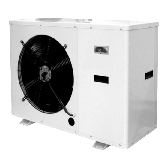
- Page 1 INSTALLATION - OPERATING - SERVICE MANUAL Air/water heat pumps, heating only, with domestic hot water production, axial-flow fans and water pump assembly. BRAN 0011M H BRAN 0025M H BRAN 0041M H...
- Page 2 INDEX U I A U I A General warnings Operating characteristics Waiver of liability General technical data Fundamental safety rules Checking and starting up the unit Receiving and handling the product HSW11 functions Description of standard unit LEDs and display Dimensioned drawings Displaying alarms Installation...
-
Page 3: General Warnings
INDEX GENERAL WARNINGS U I A U I A These appliances have been designed to chill and/or The documents supplied with the unit must be con- heat water and must be used in applications compatible signed to the owner who should keep them carefully for with their performance characteristics;... -
Page 4: Receiving And Handling The Product
RECEIVING AND HANDLING THE PRODUCT When the items are consigned by the carrier, check that The instruction manual is an integral part of the unit the packaging and the unit are undamaged. and should therefore be read and kept carefully.. If damage or missing components are noted, indicate this on The packaging should not be removed until the unit is the delivery note. -
Page 5: Versions Available
DESCRIPTION OF STANDARD UNIT These air/water heat pump with axial-flow fans operate with They are factory tested and on site installation is limited to R410A refrigerant fluid and are suitable for outdoor installa- water and electrical connections. tion. The units are CE marked, as established by the EU directives, including the latest amendments, and the corre- sponding approximated national legislation. -
Page 6: Dimensional Drawings
DIMENSIONAL DRAWINGS U I A 1 - Hydraulic connections IN 0011÷0025 Ø 3/4” - 0041 Ø 1”1/4 2 - Hydraulic connections OUT 0011÷0025 Ø 3/4” - 0041 Ø 1”1/4 Dimensions 0011 0025 0041 1240 Weight distribution 0011 0025 0041 INSTALLATION CHOICE OF INSTALLATION SITE To avoid the slings damaging the unit, place protection Before installing the unit, agree with the customer the site... -
Page 7: Water Connections
WATER CONNECTIONS The choice and installation of components is the responsibil- Failure to install the flow switches will mean the heat ity of the installer who should follow good working practice exchangers are not protected in the event of no flow of liq- and current legislation. -
Page 8: Condensate Drain
The heat pumps must be fitted with a filling/top-up sys- tem connected to the return line and a drain valve in the Electrical conductivity less than 200 mV/cm (25°C) lowest part of the system. Chlorine ions less than 50 ppm Systems containing antifreeze or covered by specific Sulphuric acid ions less than 50 ppm... - Page 9 WATER CIRCUIT DATA Size 0011 0025 0041 Water content in the system Minimum water content Freezing point (°C) Ethylene glycol solutions Water and ethylene glycol solutions used as a heat carrier in the place of water reduce the performance of the unit. Percentage of ethylene glycol in weight Multiply the performance figures by the values given in the following table.
- Page 10 OPERATING DIAGRAMS The heat pump is connected directly to the central heating circuit (the minimum water content required must be ensured). The heat pump can also produce domestic hot water by managing a special 3-way valve, connected to a hot water storage cylinder 1 Heat pump 2 Non-return valve 3 Control valve with dial...
- Page 11 OPERATING DIAGRAMS The heat pump is connected directly to the central heating circuit (the mini- mum water content required must be ensured). The heat pump can also produce domestic hot water by managing a special 3-way valve, connected to a hot water storage cylinder. 1 Heat pump 2 Non-return valve 3 Control valve with dial...
-
Page 12: Electrical Connections
Fuses (5x20T 250V) elettrica Compressor Fan/Fans Pump Total F.L.I. F.L.A. F.L.I. F.L.A. F.L.I. F.L.A. F.L.I. F.L.A. (V-Ph-Hz) (kW) (kW) (kW) (kW) BRAN 0011M H 230~50 0,15 0,21 17,6 1,25 A BRAN 0025M H 230~50 0,15 0,21 20,6 1,25 A BRAN 0041M H... -
Page 13: Electrical Panel Layout
MAINS POWER SUPPLY CONNECTIONS - Before connecting the unit to the power supply, makes - Use cable gland A for the main electrical power cable and sure that switch QF1 is open, suitably padlocked and cable gland B for other external cables to be connected by marked. - Page 14 INSTALLER CONNECTIONS All the terminals referred to in the following explanations are For remote display of the compressor operating status, an to be found on the terminal board located inside the electrical audible or visual alarm warning device can be connected panel and called “installer terminals”...
- Page 15 SINGLE-PHASE WIRING DIAGRAM BRAN 0011-0025-0041 M H GB 03/2009 BRAN H...
- Page 16 OPERATING CHARACTERISTICS Temperature control To reset normal functions, the water outlet temperature must Control is performed based on the system water return tem- rise to more than +7°C. Reset is automatic. perature. If the frost alarm is tripped more than 3 times in one hour, The set points refer to the water return temperature.
- Page 17 3-WAY VALVE MANAGEMENT FOR DOMESTIC Changeover from domestic hot water production to heating HOT WATER (YV2) system hot water production: The HSW11 controller manages domestic hot water produc- - if the DHW storage temperature (sensor BT4) has reached tion using a 3-way valve installed outside of the unit. the DHW set point (AS01);...
-
Page 18: Anti-Legionella Function
ADDITIONAL HEATER (OUTSIDE THE UNIT) (KM4) The additional heater may be configured as: The device is activated if the storage temperature (sensor - DHW storage heater. BT4) is less than the value calculated by: - Boiler replacing the heat pump. Water storage temperature (BT4) <... - Page 19 SYSTEM WATER SET POINT COMPENSATION BASED ON THE OUTSIDE TEMPERATURE The unit is fitted with an outside air temperature sensor that is used to optimise the energy efficiency of the unit based on the outside conditions. Set point compensation based on the outside temperature must be enabled by setting a parameter, see the table. System water set point compensation in HEATING mode based on the outside temperature Water temperature set point 33°C...
-
Page 20: Time Bands
TIME BANDS The HSW11 controller can manage the unit based o the time and the day of the week. The controller features four time bands in three profiles that can be combined, when programming, with the days of the week. The profile defines the behaviour of the unit over a 24 hour period. -
Page 21: General Technical Data
GENERAL TECHNICAL DATA BRAN H 0011M 0025M 0041M Heating capacity (1) 13,8 Effective input power according to EN 14511 (1) 1,82 2,31 3,68 COP according to EN 14511 (1) 3,57 3,76 3,75 Heating capacity (1) 13,8 Power absorbed (2) 1,65 2,15 3,40 COP (2) -
Page 22: Operating Limits
OPERATING LIMITS HEATING OUTLET WATER TEMPERATURE (°C) Min-max water thermal gradient 4÷6 Min-max water circuit pressure (bar) 1÷3 Max. storage temperature (°C) BRAN H GB 03/2009... -
Page 23: Checking And Starting Up The Unit
CHECKING AND STARTING UP THE UNIT PREPARING FOR FIRST START UP During this phase, if the following indications appear on The unit must be started up for the first time by the Techni- the display, follow the instructions: cal Service: Before starting up the units, make sure that: - ER20 check the water flow-rate and the connection (16 - All safety conditions have been respected;... - Page 24 HSW11 FUNCTIONS DESCRIPTION OF THE BUTTONS AND ASSOCIATED FUNCTIONS Button Description Press once Associated Press and hold Menu / Notes [press and release] function [press for about 3 seconds] - Increases a value [Manual defrost activation] Functions menu see Functions - Goes to the next label chapter (folder FnC) DOWN...
-
Page 25: Leds And Display
LEDS AND DISPLAY 1 STATUS AND OPERATING MODE LEDS 2 VALUE AND UNIT OF MEASURE LEDS Alarm Clock (RTC) Heating Degrees centigrade Standby Pressure (Bar) Defrost Menu (ABC) 3 UTILITY LEDS Compressor Not used Not used System pump Domestic hot water function activation External auxiliary heating element activation GB 03/2009 BRAN H... -
Page 26: Setting The Clock
SETTING THE CLOCK The HSW11 controller is fitted with a clock for managing time bands to control specific events. Follow the procedure shown below to set the hours, minutes and date. To set the clock of the unit, starting from the main display, press the set button. - Page 27 ... press the set button. To exit the clock setting menu press the esc button until returning to the main display. GB 03/2009 BRAN H...
-
Page 28: Selecting The Operating Mode
SELECTING THE OPERATING MODE There are three different modes: • Standby mode (StbY); in standby the compressor and pump are off but all the safety features are active • Heating mode (HEAT) For example, to switch operation from StbY to HEAT. To change the operating mode, press and hold the mode button for at least 2 seconds. -
Page 29: Setting The Set Points
SETTING THE SET POINTS As an example, the Set Point in HEAT mode will be changed from 45 degrees centigrade to 48 degrees centigrade.di. To change the set point, starting from the main display, press the set button. Pressing the set button once displays the various directo- ries. -
Page 30: Summer Mode
The instrument will display the current set point (in this case 45 degrees centigrade). To increase or decrease the value, use the up and down buttons. For example, to change the set point to 48 degrees, press the up button until the desired value is displayed. Once having reached the desired set point, press the set button. - Page 31 DISPLAYING INSTALLER PARAMETERS From the main display, press the set button. Example of displaying the analogue inputs. For the other I/Os the procedure is essentially the same***. The display will show label Ai. (Scroll the other labels using the UP and DOWN buttons until reaching the desired label).
- Page 32 DISPLAYING AUTHORISED TECHNICIAN PARAMETERS Accessing the PASS directory (from the main display, pressing the esc and set buttons together [esc+set] and scrolling to the directory with up / down) and setting the PASS accesses the parameters visible for the password entered. To access the PASS directory from the main display, press esc and set together [esc+set].
- Page 33 For parameter CF00, the value displayed will be 2. To change the value of the parameter, press the up or down button. When having selected the value, press the set button. ** To exit the display and return to the previous level, press esc.
-
Page 34: Manual Reset
MUTING AND MANUALLY RESETTING THE ALARMS The alarm signals are displayed flashing. The following procedure describes how to mute an alarm. The various errors will be displayed in directory AL (see Status menu) The errors will be displayed by alternating the error mes- sage... -
Page 35: Displaying Alarms
DISPLAYING ALARMS The alarm signals are displayed flashing. The following procedure describes how to mute an alarm. The various errors will be displayed in directory AL (see Status menu) From the main display, press the set button The display will show label Ai. Scroll the other labels using the UP and DOWN buttons until reaching label AL. - Page 36 RESET ALARM LOG Below are the instructions on how to reset the alarm log if the alarm signal Er90 is shown. To access directory FnC from the main display, press esc and set together. [esc+set]. the first directory displayed is PAr. Use the UP and DOWN buttons to scroll to the directory FnC.
- Page 37 LIST OF ACCESSIBLE PARAMETERS Directory label Meaning of the code (label) Parameters Parameters for: ConFiguration CL00... CL97 Analogue input/output configuration ConFiguration Cr00... Cr50 Analogue input configuration ConFiguration CF01... CF61 Serial configuration User interface UI00... UI36 User interface thermoregulation tr00... Tr44 Temperature control Stati (Modi di funzionamento) St00...
-
Page 38: Shutting Down For Long Periods
FAULT CAUSE SOLUTION Alarm with automatic reset Check water outlet temperature Values display indication High water outlet temperature Check water flow Er35 Check water temperature Set Point Check correct positioning of sensor BT2 Values display indication HSW11 communication error with remote Check electrical connection Er47 keypad (only if remote keypad featured) -
Page 39: Routine Maintenance
ROUTINE MAINTENANCE Never perform any cleaning operations before having - Power input; disconnected the unit from the mains power supply. - Tightness of electrical and water connections; Terminals 6, 7, 8 and 9 may be live even when the unit has - Condition of the compressor contactor;... -
Page 40: Troubleshooting
TROUBLESHOOTING FAULT CAUSE SOLUTION Check presence of voltage The heat pump doesn’t No voltage Check safety systems upstream of start the appliance Switch QF1 in OFF position Remote switch (if featured) in OFF position Control panel set to OFF Switch ON Main switch QS1 in OFF Compressor thermal overload switch OFF Supply voltage too low... - Page 41 FAULT CAUSE SOLUTION High discharge pressure High outside water temperature Check (greater than 23 bars)* High utility water inlet temperature Insufficient water flow-rate in utility heat exchanger Check pump operation (heating mode) Faulty operation of outside heat exchanger control Check (pressure regulating valves) Air in water circuit (heating mode) Vent...
- Page 42 Climaveneta Home System Via Duca d’Aosta 121 - 31030 Mignagola (TV) - Italia Tel. +39 0422 4131 - Fax +39 0422 413659...
Need help?
Do you have a question about the Bran 0011M H and is the answer not in the manual?
Questions and answers