Table of Contents
Advertisement
Quick Links
Advertisement
Table of Contents

Related Manuals for Datacom DM4000 Series

Summary of Contents for Datacom DM4000 Series
- Page 1 DM4000 Series - Installation and Operation Guide 204.0112.10...
- Page 2 Revision History Revision 10 2010/10/18 New interface boards included Revision 09 2010/01/21 New interface boards included Revision 08 2009/09/24 New pictures included Revision 07 2009/05/19 SFP pictures and new interface boards included Revision 06 2008/12/02 New pictures included Revision 05 2008/06/24 Transceivers homologation check included Revision 04 2008/01/23 CE mark information and new pictures included...
- Page 3 Although this document has been written with care, the company does not assume responsibility for occasional mis- takes and omissions in its content. Likewise, DATACOM is not liable for any damages that may result from the use of the information contained in this manual. Specifications provided in this manual are subject to changes without any...
- Page 4 Contact Information In order to contact the DATACOM technical support, or sales department: Support: • E-mail: suporte@datacom.ind.br • Phone: +55 51 3358-0122 • Fax: +55 51 3358-0101 • Sales: • E-mail: comercial@datacom.ind.br • Phone: +55 51 3358-0100 • Fax: +55 51 3358-0101 •...
- Page 5 Conventions General Information: Symbol Description Notes give an explanation about some topic in the foregoing paragraph. Safety information Symbol Description Generic alarm symbol: To suggest a general safety ESD protection symbol: To suggest electrostatic-sensitive equipment Electric shock symbol: To suggest a danger of high voltage Microwave symbol: To suggest a high-intensity electromagnetic field...
-
Page 6: Table Of Contents
Table of Contents 1. General Recommendation........................1 1.1. Before the Installation .........................1 2. Introduction............................3 2.1. About this guide ..........................3 2.2. Overview .............................3 3. Technical Specifications.........................7 3.1. Environmental Conditions......................7 3.2. Power Supply ..........................7 3.2.1. DM4001..........................7 3.2.2. DM4004..........................8 3.2.3. DM4008..........................9 3.2.4. Interface Modules ......................9 3.3. - Page 7 9. DM4000 MPU416..........................34 9.1. Overview ...........................34 9.2. Front Panel Description......................35 9.3. System Status LEDs........................35 9.4. Console and Ethernet Outband Management Ports ..............36 10. DM4000 ETH24GX ...........................38 10.1. Overview ..........................38 10.2. Front Panel Description......................39 10.3. System Status LEDs........................39 10.4. Software and Hardware Features ....................40 10.4.1.
- Page 8 15.4.1. Software........................60 15.4.2. Hardware ........................60 16. DM4000 ETH48GT ...........................62 16.1. Overview ..........................62 16.2. Front Panel Description......................62 16.3. System Status LEDs........................63 16.4. Software and Hardware Features ....................64 16.4.1. Software........................64 16.4.2. Hardware ........................64 17. DM4000 ETH48GX H Series......................66 17.1. Overview ..........................66 17.2. Front Panel Description......................66 17.3.
- Page 9 23. DM4000 GPC-DCM ..........................86 23.1. Overview ..........................86 23.2. Front Panel Description......................87 24. Fan Board ............................88 24.1. Description ..........................88 24.2. Air Flow ..........................89 24.2.1. DM4004 and DM4008 Chassis ..................89 25. Installation Guide ..........................91 25.1. Installation Kit.........................91 25.2. Powering the Switch .......................92 25.2.1.
-
Page 10: List Of Tables
List of Tables 3-1. Recommended Power Limits and Consumption Parameters for DM4001 ..........7 3-2. Absolute Power Limits for DM4001....................?? 3-3. Recommended Power Limits and Consumption Parameters for DM4004 ..........8 3-4. Absolute Power Limits for DM4004....................8 3-5. Recommended Power Limits and Consumption Parameters for DM4008 ..........9 3-6. - Page 11 21-2. DM4000 GPC-OAB Port Status LEDs ....................83 22-1. Pre-amplifier parameters ........................85 22-2. DM4000 GPC-OAP Port Status LEDs.....................85 23-1. DCM parameters ..........................87 25-1. Cable dimension according chassis....................94 25-2. Gigabit SFP Modules ........................102 A-1. Cable DB9-RJ-45 ..........................104 C-1. Applicable Standards ........................107...
-
Page 12: General Recommendation
Chapter 1. General Recommendation 1.1. Before the Installation "Before the installation, read the entire manual attentively." "The installation of any electric equipment must be in accordance with the current law in the place where this equipment will be installed. This includes adequate devices of protection, sizing and protection to the capacities of the equipment."... - Page 13 Chapter 1. General Recommendation "Some equipment in this manual have laser emitting optical modules. Avoid the exposure to eyes and skin." "WEEE Directive Symbol (Applicable in the European Union and other European countries with separate collection systems).This symbol on the product or its packaging indicates that this product must not be disposed of with other waste.
-
Page 14: Introduction
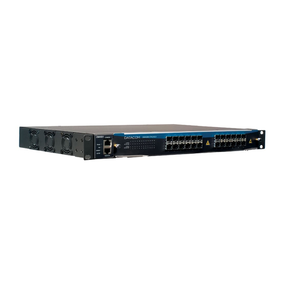
Chapter 2. Introduction 2.1. About this guide This guide can be used for all DATACOM DM4000 Metro Ethernet Series, providing information about installation and characteristics of the DM4000 family. This guide focuses on the physical, electrical, status indications and installation portion of the hardware. It is assumed that the individual or individuals managing any aspect of this product have basic understanding of Switching, Routing, Ethernet, and general Telecommunications. - Page 15 Graphical User Interface that allows complete state and fail monitoring conditions, configuration man- agement and inventory, perfect for higher network sizes. DM4000 Series is the perfect choice for the core of your network, ensuring its reliability and scalability. The Chassis models available are as follows: DM4001 Chassis - 19"...
-
Page 16: Dm4000 Mpu416
SFPs are 100Base-FX, 1000Base-X and SGMII compatible. DM4000 ETH4x10GX H Series - Hot swappable 4 ports 10 Gigabit XFP interface board. • MPUs (Main Processor Unit) available in DM4000 Series: DM4000 MPU192 - Non-blocking, redundant and hot swappable Main Processor Unit, capable of •... - Page 17 Chapter 2. Introduction DM4000 ETH12GX+1x10GX using a MPU192 in a DM4008 Chassis • Different MPUs cannot be used in the same chassis. You must use both MPUs of the same type (two MPU192, MPU384 or MPU416)
-
Page 18: Technical Specifications
Chapter 3. Technical Specifications 3.1. Environmental Conditions Operating Temperature: 0 to 55 degrees Celsius Storage Temperature: -20 to 65 degrees Celsius Humidity: 10 to 90% non condensing 3.2. Power Supply The DM4000 family has a DC power input range of -48 to -60 V WARNING: "Before connecting any cable to the equipment, be sure that the grounding system is functional."... -
Page 19: Dm4004
Chapter 3. Technical Specifications Table 3-2. Absolute Power Limits for DM4001 Absolute Voltage Limits Power Type Power max. Current max. min. max. -36V -72V 200W 4.7A Follow Power information below screws to correct RET / -48V connections Figure 3-1. DM4001 Power Supplies Connectors 3.2.2. -
Page 20: Dm4008
Chapter 3. Technical Specifications Figure 3-2. DM4004 Power Supplies Connectors 3.2.3. DM4008 Table 3-5. Recommended Power Limits and Consumption Parameters for DM4008 Rec. Voltage Limits Power Type Power max. Current max. min. max. -48V -60V 1200W 25.00A Table 3-6. Absolute Power Limits for DM4008 Absolute Voltage Limits Power Type Power max. -
Page 21: Dimensions
Chapter 3. Technical Specifications Interface Module Fuse Consumption ETH2x10GX 3.15A fuse, type T (delay), 250V ETH2x10GX H Series 3.15A fuse, type T (delay), 250V ETH24GT 3.15A fuse, type T (delay), 250V ETH48GT 3.15A fuse, type T (delay), 250V 110W ETH48GX H Series 3.15A fuse, type T (delay), 250V ETH4x10GX H Series 3.15A fuse, type T (delay), 250V... -
Page 22: Mpus
Chapter 3. Technical Specifications Kilograms (kg) Pounds (lbs) DM4004 19" 1.49 3.28 DM4004 23" 1.31 2.89 DM4008 2.68 5.90 Table 3-10. MPUs Kilograms (kg) Pounds (lbs) MPU192 0.97 2.13 MPU384 1.12 2.47 MPU416 1.12 2.47 Table 3-11. Interface Boards Interface Board Kilograms (kg) Pounds (lbs) ETH24GX... - Page 23 Chapter 3. Technical Specifications Panel Kilograms (kg) Pounds (lbs) Interface Boards Blank Panel 2.68 5.90 MPUs Blank Panel 0.09 0.19 GPCs Blank Panel 0.05 0.11...
-
Page 24: Dm4001 Chassis
Chapter 4. DM4001 Chassis 4.1. Overview The DM4001 chassis is compatible with all interface boards of the DM4000 Series, allowing their utiliza- tion as a standalone version. Its backplane interface allows non-blocking wire speed data of all interface boards connected. -
Page 25: Front Panel Description
Chapter 4. DM4001 Chassis 4.2. Front Panel Description The Front Panel of the DM4001 chassis has a RS232 Console port, an Ethernet Outband Management interface and Status LEDs. Figure 4-2. DM4001 Chassis - Front Panel 4.3. System Status LEDs The System Status LEDs on the front panel can be used to monitor system activity. The following figure shows where the LEDs are located and the table below indicates the system status according to each LEDs condition. -
Page 26: Console And Ethernet Outband Management Ports
Chapter 4. DM4001 Chassis Table 4-1. System LEDs DM4001 Chassis CONDITION STATUS Power Equipment on. Equipment off. Fail Indicates fail (high temperature or fan fail). Equipment operates normally. Link/Act ON/Blinking Connected with link up. Blinking indicates activity. No connection established. Speed 10Mbit/s connection established. -
Page 27: Rear Panel Description
Chapter 4. DM4001 Chassis Table 4-2. Interface Pinout Management Port RJ-45 Signal 4,5,7,8 RJ-45 Serial Port 1,2,7,8 4.5. Rear Panel Description The Rear Panel of the DM4001 chassis has two 48 to 60V DC power inputs. Figure 4-5. DM4001 Rear Panel Note: The figure above represents the last version of Rear Panel, another version could be different. -
Page 28: Dm4004 Chassis
Chapter 5. DM4004 Chassis 5.1. Overview The DM4004 chassis is compatible with all MPUs and interface boards of the DM4000 Series. It is available in two versions: for use in 19" and 23" racks. The 19" chassis is the standard version while the 23"... -
Page 29: Front Panel Description
Chapter 5. DM4004 Chassis Figure 5-2. DM4004 Chassis 23" For normal operation blank panels are required for non slotted interface boards and MPUs. 5.2. Front Panel Description The main power input connectors are located in the Front Panel of DM4004 chassis. It supports dual redundant DC inputs for 48V DC nominal operation. -
Page 30: Rear Panel Description
Chapter 5. DM4004 Chassis Figure 5-3. DM4004 Chassis 19" - Front Panel Figure 5-4. DM4004 Chassis 23" - Front Panel 5.3. Rear Panel Description The DM4004 chassis Rear Panel has one console DB9 connector. -
Page 31: Console Management Port
Chapter 5. DM4004 Chassis Figure 5-5. DM4004 Chassis 19" - Rear Panel Figure 5-6. DM4004 Chassis 23" - Rear Panel 5.4. Console Management Port The chassis contains one DB9 connector on its rear panel. The connector has two Console ports, each one connected to each MPU. -
Page 32: Db9 Pins Specification
Chapter 5. DM4004 Chassis Figure 5-7. DB9 Pins Specification Table 5-1. DB9 Pins Specification Signal 1,4,6,9 MPU-A TX MPU-A RX MPU-B TX MPU-B RX... -
Page 33: Dm4008 Chassis
Chapter 6. DM4008 Chassis 6.1. Overview The DM4008 chassis is compatible with all MPUs and interface boards of the DM4000 Series. It has eight interface board slots, two MPU slots, two multipurpose slots and one FAN module slot. Figure 6-1. DM4008 Chassis... -
Page 34: Front Panel Description
Chapter 6. DM4008 Chassis 6.2. Front Panel Description The main power input connectors are located in the Front Panel of DM4008 chassis. It supports dual redundant DC inputs for 48V DC nominal operation. Figure 6-2. DM4008 Chassis - Front Panel 6.3. -
Page 35: Console Management Port
Chapter 6. DM4008 Chassis Figure 6-3. DM4008 Chassis - Rear Panel 6.4. Console Management Port The chassis contains one DB9 connector on its rear panel. The connector has two Console ports, each one connected to each MPU. The pinouts of the Console ports are shown in the following figure and table. Figure 6-4. -
Page 36: Db9 Pins Specification
Chapter 6. DM4008 Chassis Table 6-1. DB9 Pins Specification Signal 1,4,6,9 MPU-A TX MPU-A RX MPU-B TX MPU-B RX... -
Page 37: Dm4000 Mpu192
Chapter 7. DM4000 MPU192 7.1. Overview The DM4000 MPU192 is a hot-swappable Switch Fabric module capable of handling 192Gbps of non- blocking data (up to 96 Gigabit Ethernet ports). It is compatible with DM4004 and DM4008 chassis. In the DM4004 chassis it can handle up to 24 Gigabit ports per interface module at a non blocking configuration. In the DM4008 it can handle up to 12 Gigabit Ethernet ports per interface module board at a non-blocking configuration. -
Page 38: Front Panel Description
Chapter 7. DM4000 MPU192 CAUTION: "Risk of explosion if battery is replaced by an incorrect type. Use only cell type CR2032. Dispose of used batteries according with local regulations." 7.2. Front Panel Description The DM4000 MPU192 Front Panel has system status LEDs, one Ethernet Outband Management port (MGMT ETH), one RS-232 Serial port (Console) and one Auxiliar port (AUX). -
Page 39: Console And Ethernet Outband Management Ports
Chapter 7. DM4000 MPU192 7.3. System Status LEDs The DM4000 MPU192 has 9 system status LEDs monitoring CPU utilization, Ethernet outband, system fails and active MPU status. Figure 7-3. DM4000 MPU192 - Front Panel LEDs Table 7-1. MPU192 System LEDs CONDITION STATUS ACT MPU... -
Page 40: Interface Pinout
Chapter 7. DM4000 MPU192 The pinouts of both Console and Outband Management ports are shown in the table below. Figure 7-4. DM4000 MPU192 - Front Panel Connectors Table 7-2. Interface Pinout Management Port Signal 4,5,7,8 Console Port 1,2,7,8 AUX Port 1,2,7,8... -
Page 41: Dm4000 Mpu384
Chapter 8. DM4000 MPU384 8.1. Overview The DM4000 MPU384 is a hot-swappable Switch Fabric module capable of handling 384Gbps of non- blocking data (up to 192 Gigabit Ethernet ports). It is compatible with DM4004 and DM4008 chassis. In the DM4004 chassis it can handle up to 48 Gigabit Ethernet ports per interface board at a non-blocking configuration. -
Page 42: Front Panel Description
Chapter 8. DM4000 MPU384 CAUTION: "Risk of explosion if battery is replaced by an incorrect type. Use only cell type CR2032. Dispose of used batteries according with local regulations." 8.2. Front Panel Description The DM4000 MPU384 Front Panel has system status LEDs, one Ethernet Outband Management port (MGMT ETH), one RS-232 Serial port (Console) and one Auxiliar port (AUX). -
Page 43: Console And Ethernet Outband Management Ports
Chapter 8. DM4000 MPU384 8.3. System Status LEDs The DM4000 MPU384 has 9 system status LEDs monitoring CPU utilization, Ethernet outband, system fails and active MPU status. Figure 8-3. DM4000 MPU384 - Front Panel LEDs Table 8-1. MPU384 System LEDs CONDITION STATUS ACT MPU... -
Page 44: Interface Pinout
Chapter 8. DM4000 MPU384 The pinouts of both Console and Outband Management ports are shown in the table below. Figure 8-4. DM4000 MPU384 - Front Panel Connectors Table 8-2. Interface Pinout Management Port Signal 4,5,7,8 Console Port 1,2,7,8 AUX Port 1,2,7,8... - Page 45 Chapter 9. DM4000 MPU416 9.1. Overview The DM4000 MPU416 is a hot-swappable Switch Fabric module capable of handling 416Gbps of non- blocking data (up to 208 Gigabit Ethernet ports). It is compatible with DM4004 and DM4008 chassis. In the DM4004 chassis it can handle up to 52 Gigabit Ethernet ports per interface board at a non-blocking configuration.
-
Page 46: Front Panel Description
Chapter 9. DM4000 MPU416 CAUTION: "Risk of explosion if battery is replaced by an incorrect type. Use only cell type CR2032. Dispose of used batteries according with local regulations." 9.2. Front Panel Description The DM4000 MPU416 Front Panel has system status LEDs, one Ethernet Outband Management port (MGMT ETH), one RS-232 Serial port (Console) and one Auxiliar port (AUX). - Page 47 Chapter 9. DM4000 MPU416 9.3. System Status LEDs The DM4000 MPU416 has 9 system status LEDs monitoring CPU utilization, Ethernet outband, system fails and active MPU status. Figure 9-3. DM4000 MPU416 - Front Panel LEDs Table 9-1. MPU416 System LEDs CONDITION STATUS ACT MPU...
-
Page 48: Interface Pinout
Chapter 9. DM4000 MPU416 The pinouts of both Console and Outband Management ports are shown in the table below. Figure 9-4. DM4000 MPU416 - Front Panel Connectors Table 9-2. Interface Pinout Management Port Signal 4,5,7,8 Console Port 1,2,7,8 AUX Port 1,2,7,8... -
Page 49: Dm4000 Eth24Gx
Chapter 10. DM4000 ETH24GX 10.1. Overview The DM4000 ETH24GX is a non-blocking 24 SFP port interface board compatible with DM4001, DM4004 and DM4008 chassis. The DM4000 ETH24GX can handle up to 35,714,285 packets per second supporting 9600 bytes jumbo frames and has an internal 256MB Switching Memory supporting wire speed operation. The DM4000 ETH24GX has a 400MHz microprocessor with 256MB of RAM and 64MB of Flash. -
Page 50: Front Panel Description
Chapter 10. DM4000 ETH24GX CAUTION: "Risk of explosion if battery is replaced by an incorrect type. Use only cell type CR2032. Dispose of used batteries according with local regulations." 10.2. Front Panel Description DM4000 ETH24GX front panel contains 24 SFP slots and port status LEDs. Figure 10-2. -
Page 51: System Status Leds
Chapter 10. DM4000 ETH24GX 10.3. System Status LEDs The DM4000 ETH24GX has the following port status LEDs. Figure 10-3. DM4000 ETH24GX - Front Panel LEDs Table 10-1. ETH24GX Port Status LEDs CONDITION STATUS Link/Act ON/Blinking Connection established. Blinking indicates port activity. -
Page 52: Hardware
Chapter 10. DM4000 ETH24GX 10.4.2. Hardware Table 10-2. Hardware DM4000 ETH24GX Feature Description Switch L2 Wire Speed Router 3 Wire Speed L2-L4 MPLS LDP/RSVP/L2VPN Ports 24 x 1000Base-X (SFP) Packet Buffer 128MB Switch Fabric (intern) 48Gbps Flash 64MB SDRAM 256MB MAC address table 1024k* L3 hosts (IPv4) -
Page 53: Dm4000 Eth24Gx H Series
Chapter 11. DM4000 ETH24GX H Series 11.1. Overview The DM4000 ETH24GX H Series is a non-blocking 24 SFP port interface board compatible with DM4001, DM4004 and DM4008 chassis. The DM4000 ETH24GX H Series can handle up to 35,714,285 packets per second supporting 12K jumbo frames and has an internal 4MB Switching Memory supporting wire speed operation. -
Page 54: Front Panel Description
Chapter 11. DM4000 ETH24GX H Series 11.2. Front Panel Description DM4000 ETH24GX H Series front panel contains 24 SFP slots and port status LEDs. Figure 11-2. DM4000 ETH24GX H Series - Front Panel WARNING: "When performing installation and maintenance operations of optical fibers, you should not stand close or look directly into the fiber outlet with unaided eyes."... -
Page 55: System Status Leds
Chapter 11. DM4000 ETH24GX H Series 11.3. System Status LEDs The DM4000 ETH24GX H Series has the following port status LEDs. Table 11-1. ETH24GX H Series Port Status LEDs CONDITION STATUS Link/Act ON/Blinking Connection established. Blinking indicates port activity. No connection established. 10/100/1000 Indicates that a 10/100Mbps connection was established. -
Page 56: Hardware
Chapter 11. DM4000 ETH24GX H Series 11.4.2. Hardware Table 11-2. Hardware DM4000 ETH24GX H Series Feature Description Switch L2 Wire Speed Router L3 Wire Speed L2-L4 MPLS LDP/RSVP/L2VPN VPLS VPN Emulated LAN VPWS VPN Point-to-Point Ports 24 SFP** Packet Buffer Switch Fabric (intern) 48Gbps Flash... -
Page 57: Dm4000 Eth12Gx
Chapter 12. DM4000 ETH12GX 12.1. Overview The DM4000 ETH12GX is a non-blocking 12 SFP port interface board compatible with DM4001, DM4004 and DM4008 chassis. The DM4000 ETH12GX can handle up to 17,857,142 packets per second supporting 9600 bytes jumbo frames and has an internal 128MB Switching Memory supporting wire speed operation. The DM4000 ETH12GX has a 400MHz microprocessor with 256MB of RAM and 64MB of Flash. -
Page 58: Front Panel Description
Chapter 12. DM4000 ETH12GX CAUTION: "Risk of explosion if battery is replaced by an incorrect type. Use only cell type CR2032. Dispose of used batteries according with local regulations." 12.2. Front Panel Description DM4000 ETH12GX front panel contains 12 SFP ports and port status LEDs. Figure 12-2. -
Page 59: System Status Leds
Chapter 12. DM4000 ETH12GX 12.3. System Status LEDs The DM4000 ETH12GX has the following port status LEDs. Figure 12-3. DM4000 ETH12GX - Front Panel LEDs Table 12-1. ETH12GX Port Status LEDs CONDITION STATUS Link/Act ON/Blinking Connection established. Blinking indicates port activity. -
Page 60: Hardware
Chapter 12. DM4000 ETH12GX 12.4.2. Hardware Table 12-2. Hardware DM4000 ETH12GX Feature Description Switch L2 Wire Speed Router 3 Wire Speed L2-L4 MPLS LDP/RSVP/L2VPN Ports 12 x 1000Base-X (SFP) Packet Buffer 128MB Switch Fabric (intern) 24Gbps Flash 64MB SDRAM 256MB MAC address table 512k* L3 hosts (IPv4) -
Page 61: Dm4000 Eth12Gx+1X10Gx
Chapter 13. DM4000 ETH12GX+1x10GX 13.1. Overview The DM4000 ETH12GX+1x10GX is a non-blocking 12 SFP port plus one 10 Gigabit XFP port interface board compatible with DM4001, DM4004 and DM4008 chassis. The DM4000 ETH12GX+1x10GX can handle up to 32,738,095 packets per second supporting 9600 bytes jumbo frames and has an internal 256MB Switching Memory supporting wire speed operation. -
Page 62: Front Panel Description
Chapter 13. DM4000 ETH12GX+1x10GX CAUTION: "Risk of explosion if battery is replaced by an incorrect type. Use only cell type CR2032. Dispose of used batteries according with local regulations." 13.2. Front Panel Description DM4000 ETH12GX+1x10GX front panel contains 12 SFP ports, 1 XFP port and port status LEDs. Figure 13-2. -
Page 63: System Status Leds
Chapter 13. DM4000 ETH12GX+1x10GX 13.3. System Status LEDs The DM4000 ETH12GX+1x10GX has the following port status LEDs. Figure 13-3. DM4000 ETH12GX+1x10GX - Front Panel LEDs Table 13-1. ETH12GX+1x10GX Port Status LEDs CONDITION STATUS Link/Act ON/Blinking Connection established. Blinking indicates port activity. -
Page 64: Hardware
Chapter 13. DM4000 ETH12GX+1x10GX 13.4.2. Hardware Table 13-2. Hardware DM4000 ETH12GX+1x10GX Feature Description Switch L2 Wire Speed Router 3 Wire Speed L2-L4 MPLS LDP/RSVP/L2VPN Ports 12 x 1000Base-X (SFP) + 1 x 10G (XFP) Packet Buffer 128MB Switch Fabric (intern) 44Gbps Flash 64MB... -
Page 65: Dm4000 Eth2X10Gx
Chapter 14. DM4000 ETH2x10GX 14.1. Overview The DM4000 ETH2x10GX is a non-blocking two 10 Gigabit XFP port interface board compatible with DM4001, DM4004 and DM4008 chassis. The DM4000 ETH2x10GX can handle up to 29,761,904 packets per second supporting 9600 bytes jumbo frames and has an internal 256MB Switching Memory supporting wire speed operation. -
Page 66: Front Panel Description
Chapter 14. DM4000 ETH2x10GX CAUTION: "Risk of explosion if battery is replaced by an incorrect type. Use only cell type CR2032. Dispose of used batteries according with local regulations." 14.2. Front Panel Description DM4000 ETH2x10GX front panel contains 2 XFP ports and port status LEDs. Figure 14-2. -
Page 67: System Status Leds
Chapter 14. DM4000 ETH2x10GX 14.3. System Status LEDs The DM4000 ETH2x10GX has the following port status LEDs. Figure 14-3. DM4000 ETH2x10GX - Front Panel LEDs Table 14-1. ETH2x10GX Port Status LEDs CONDITION STATUS Link/Act ON/Blinking Connection established. Blinking indicates port activity. -
Page 68: Hardware
Chapter 14. DM4000 ETH2x10GX 14.4.2. Hardware Table 14-2. Hardware DM4000 ETH2x10GX Feature Description Switch L2 Wire Speed Router 3 Wire Speed L2-L4 MPLS LDP/RSVP/L2VPN Ports 2 x 10G (XFP) Packet Buffer 128MB Switch Fabric (intern) 40 Gbps Flash 64MB SDRAM 256MB MAC address table 1024k*... -
Page 69: Dm4000 Eth24Gt
Chapter 15. DM4000 ETH24GT 15.1. Overview The DM4000 ETH24GT is a non-blocking 24 10/100/1000Mbps port interface board compatible with DM4001, DM4004 and DM4008 chassis. The DM4000 ETH24GT can handle up to 35,714,285 packets per second supporting 9500 bytes jumbo frames reaching wire speed operation. The DM4000 ETH24GT has a 400MHz microprocessor with 256MB of RAM and 64MB of Flash. -
Page 70: Front Panel Description
Chapter 15. DM4000 ETH24GT 15.2. Front Panel Description The ETH24GT front panel contains 24 RJ45 ports and port status LEDs. With option to have PoE in all ports. Figure 15-2. DM4000 ETH24GT - Front Panel WARNING: "Electrostatic generated by human body may damage the electrostatic sensitive components on equip- ment."... -
Page 71: System Status Leds
Chapter 15. DM4000 ETH24GT 15.3. System Status LEDs The DM4000 ETH24GT has the following port status LEDs: Table 15-1. ETH24GT Port Status LEDs CONDITION STATUS Link/Act ON/Blinking Connection established. Blinking indicates port activity. No connection established. 10/100/1000 Orange Indicates that a 10/100Mbps connection was established. -
Page 72: Hardware
Chapter 15. DM4000 ETH24GT 15.4.2. Hardware Table 15-2. Hardware DM4000 ETH24GT Feature Description Switch L2 Wire Speed Router 3 Wire Speed L2-L4 MPLS Ports 24 x 10/100/1000 Base-TX Packet Buffer Switch Fabric (intern) 48Gbps Flash 64MB SDRAM 256MB MAC address table L3 hosts (IPv4) L3 hosts (IPv6) L3 Routes (IPv4) -
Page 73: Dm4000 Eth48Gt
Chapter 16. DM4000 ETH48GT 16.1. Overview The DM4000 ETH48GT is a non-blocking 48 10/100/1000Mbps port interface board compatible with DM4001, DM4004 and DM4008 chassis. The DM4000 ETH48GT can handle up to 71,428,571 packets per second supporting 9500 bytes jumbo frames reaching wire speed operation. The DM4000 ETH48GT has a 400MHz microprocessor with 256MB of RAM and 64MB of Flash. -
Page 74: Front Panel Description
Chapter 16. DM4000 ETH48GT 16.2. Front Panel Description The ETH48GT front panel contains 48 RJ45 ports and port status LEDs. With option to have PoE in all ports. Figure 16-2. DM4000 ETH48GT- Front Panel WARNING: "Electrostatic generated by human body may damage the electrostatic sensitive components on equip- ment."... -
Page 75: System Status Leds
Chapter 16. DM4000 ETH48GT 16.3. System Status LEDs The DM4000 ETH48GT has the following port status LEDs: Table 16-1. ETH48GT Port Status LEDs CONDITION STATUS Link/Act ON/Blinking Connection established. Blinking indicates port activity. No connection established. 10/100/1000 Orange Indicates that a 10/100Mbps connection was established. -
Page 76: Hardware
Chapter 16. DM4000 ETH48GT 16.4.2. Hardware Table 16-2. Hardware DM4000 ETH48GT Feature Description Switch L2 Wire Speed Router 3 Wire Speed L2-L4 MPLS Ports 48 x 10/100/1000 Base-TX Packet Buffer Switch Fabric (intern) 96Gbps Flash 64MB SDRAM 256MB MAC address table L3 hosts (IPv4) L3 hosts (IPv6) L3 Routes (IPv4) -
Page 77: Dm4000 Eth48Gx H Series
Chapter 17. DM4000 ETH48GX H Series 17.1. Overview The DM4000 ETH48GX H Series is a non-blocking 48 SFP port interface board compatible with DM4001, DM4004 and DM4008 chassis. The DM4000 ETH84GX H Series can handle up to 71,428,571 packets per second supporting 12KB jumbo frames and has an internal 4MB Switching Memory supporting wire speed operation. -
Page 78: Front Panel Description
Chapter 17. DM4000 ETH48GX H Series 17.2. Front Panel Description DM4000 ETH48GX H Series front panel contains 48 SFP slots and port status LEDs. Figure 17-2. DM4000 ETH48GX H Series - Front Panel WARNING: "Electrostatic generated by human body may damage the electrostatic sensitive components on equip- ment."... -
Page 79: System Status Leds
Chapter 17. DM4000 ETH48GX H Series 17.3. System Status LEDs The DM4000 ETH48GX H Series has the following port status LEDs: Table 17-1. ETH48GX H Series Port Status LEDs CONDITION STATUS Link/Act ON/Blinking Connection established. Blinking indicates port activity. No connection established. 10/100/1000 Orange Indicates that a 10/100Mbps connection was... -
Page 80: Hardware
Chapter 17. DM4000 ETH48GX H Series 17.4.2. Hardware Table 17-2. Hardware DM4000 ETH48GX H Series Feature Description Switch L2 Wire Speed Router L3 Wire Speed L2-L4 MPLS LDP/RSVP/L2VPN VPLS VPN Emulated LAN VPWS VPN Point-to-Point Ports 48 x SFP** Packet Buffer Switch Fabric (intern) 96Gbps Flash... -
Page 81: Dm4000 Eth24Gx+2X10Gx H Series
Chapter 18. DM4000 ETH24GX+2x10GX H Series 18.1. Overview The DM4000 ETH24GX+2x10GX H Series is a non-blocking 24 SFP port plus two 10 Gigabit XFP port interface board compatible with DM4001, DM4004 and DM4008 chassis. The DM4000 ETH24GX+2x10GX H Series can handle up to 65,476,190 packets per second supporting 12KB jumbo frames and has an internal 4MB Switching Memory supporting wire speed operation. -
Page 82: Front Panel Description
Chapter 18. DM4000 ETH24GX+2x10GX H Series 18.2. Front Panel Description DM4000 ETH24GX+2x10GX front panel contains 24 SFP ports, 2 XFPs port and port status LEDs. Figure 18-2. DM4000 ETH24GX+2x10GX H Series - Front Panel WARNING: "When performing installation and maintenance operations of optical fibers, you should not stand close or look directly into the fiber outlet with unaided eyes."... -
Page 83: System Status Leds
Chapter 18. DM4000 ETH24GX+2x10GX H Series 18.3. System Status LEDs The DM4000 ETH24GX+2x10GX H Series has the following port status LEDs. Table 18-1. ETH24GX+2x10GX H Series Port Status LEDs CONDITION STATUS Link/Act ON/Blinking Connection established. Blinking indicates port activity. No connection established. 10/100/1000 Indicates that a 10/100Mbps connection was established. -
Page 84: Hardware
Chapter 18. DM4000 ETH24GX+2x10GX H Series 18.4.2. Hardware Table 18-2. Hardware DM4000 ETH24GX+2x10GX H Series Feature Description Switch L2 Wire Speed Router L3 Wire Speed L2-L4 MPLS LDP/RSVP/L2VPN VPLS VPN Emulated LAN VPWS VPN Point-to-Point Ports 24 x SFP** + 2 x 10G (XFP) Packet Buffer Switch Fabric (intern) 88Gbps... -
Page 85: Dm4000 Eth2X10Gx H Series
Chapter 19. DM4000 ETH2x10GX H Series 19.1. Overview The DM4000 ETH2x10GX H Series is a non-blocking two 10 Gigabit XFP port interface board compat- ible with DM4001, DM4004 and DM4008 chassis. The DM4000 ETH2x10GX H Series can handle up to 29,761,904 packets per second supporting 12KB jumbo frames and has an internal 4MB Switching Memory supporting wire speed operation. -
Page 86: Front Panel Description
Chapter 19. DM4000 ETH2x10GX H Series 19.2. Front Panel Description DM4000 ETH2x10GX front panel contains 2 XFPs port and port status LEDs. Figure 19-2. DM4000 ETH2x10GX H Series - Front Panel WARNING: "When performing installation and maintenance operations of optical fibers, you should not stand close or look directly into the fiber outlet with unaided eyes."... -
Page 87: System Status Leds
Chapter 19. DM4000 ETH2x10GX H Series 19.3. System Status LEDs The DM4000 ETH2x10GX H Series has the following port status LEDs. Table 19-1. ETH2x10GX H Series Port Status LEDs CONDITION STATUS Link/Act ON/Blinking Connection established. Blinking indicates port activity. No connection established. Laser TX On Indicates that XFP TX laser is on. -
Page 88: Hardware
Chapter 19. DM4000 ETH2x10GX H Series 19.4.2. Hardware Table 19-2. Hardware DM4000 ETH2x10GX H Series Feature Description Switch L2 Wire Speed Router L3 Wire Speed L2-L4 MPLS LDP/RSVP/L2VPN VPLS VPN Emulated LAN VPWS VPN Point-to-Point Ports 24 x 1000Base-X (SFP) + 2 x 10G (XFP) Packet Buffer Switch Fabric (intern) 88Gbps... -
Page 89: Dm4000 Eth4X10Gx H Series
Chapter 20. DM4000 ETH4x10GX H Series 20.1. Overview The DM4000 ETH4x10GX H Series is a non-blocking four 10 Gigabit XFP port interface board compat- ible with DM4001, DM4004 and DM4008 chassis The DM4000 ETH4x10GX H Series can handle up to 59,523,808 packets per second supporting 12KB jumbo frames and has an internal 4MB Switching Memory supporting wire speed operation. -
Page 90: Front Panel Description
Chapter 20. DM4000 ETH4x10GX H Series 20.2. Front Panel Description DM4000 ETH4x10GX H Series front panel contains 4 XFPs port and port status LEDs. Figure 20-2. DM4000 ETH4x10GX H Series - Front Panel WARNING: "When performing installation and maintenance operations of optical fibers, you should not stand close or look directly into the fiber outlet with unaided eyes."... -
Page 91: System Status Leds
Chapter 20. DM4000 ETH4x10GX H Series 20.3. System Status LEDs The DM4000 ETH4x10GX H Series has the following port status LEDs. Table 20-1. ETH4x10GX H Series Port Status LEDs CONDITION STATUS Link/Act ON/Blinking Connection established. Blinking indicates port activity. No connection established. 10/100/1000 Indicates that a 10/100Mbps connection was established. -
Page 92: Hardware
Chapter 20. DM4000 ETH4x10GX H Series 20.4.2. Hardware Table 20-2. Hardware DM4000 ETH4x10GX H Series Feature Description Switch L2 Wire Speed Router L3 Wire Speed L2-L4 MPLS LDP/RSVP/L2VPN VPLS VPN Emulated LAN VPWS VPN Point-to-Point Ports 4 x 10G (XFP) Packet Buffer Switch Fabric (intern) 80Gbps... -
Page 93: Dm4000 Gpc-Oab
Chapter 21. DM4000 GPC-OAB 21.1. Overview DM4000 GPC-OAB is an active booster amplifier based on erbium doped fiber (EDF). The module am- plifies optical signals, allowing extension of optical loop up to 10 Gbit/s. Booster’s output power can be configured through terminal, management system or locally. It can be managed by host equipment or directly. -
Page 94: Front Panel Description
Chapter 21. DM4000 GPC-OAB CAUTION: "Amplification module uses transmitters with no-visible class 3B laser radiation. Never look directly to the laser terminals or to the optical fiber. The exposure to the laser emission can cause total or partial loss of vision." Parameters from DM4000 GPC-OAB Table 21-1. -
Page 95: Dm4000 Gpc-Oap
Chapter 22. DM4000 GPC-OAP 22.1. Overview DM4000 GPC-OAP is an active pre-amplifier based on erbium doped fiber (EDF). The module amplifies attenuated optical signals, making possible its detection by receptor. DM4000 GPC-OAP allows extension of optical loop up to 10 Gbit/s. It can be managed by host equipment or directly. -
Page 96: Front Panel Description
Chapter 22. DM4000 GPC-OAP CAUTION: "Amplification module uses transmitters with no-visible class 3B laser radiation. Never look directly to the laser terminals or to the optical fiber. The exposure to the laser emission can cause total or partial loss of vision." Parameters from DM4000 GPC-OAP Table 22-1. -
Page 97: Dm4000 Gpc-Dcm
Chapter 23. DM4000 GPC-DCM 23.1. Overview DM4000 GPC-DCM is an Dispersion-compensating Module. The module compensates 40 km of the dispersion of the fiber being used in a transmission system. Its optimized for use in Nondispersion-Shifted Fiber (ITU-T G.652). The DM4000 GPC-DCM is a passive module and do not need to be powered to work. The DM4000 GPC-DCM is designed to work with Transceivers that are design for DWDM, the Dispersion Level is not guaranteed for lambdas outside ITU-T DWDM Grid. -
Page 98: Front Panel Description
Chapter 23. DM4000 GPC-DCM Parameters from DM4000 GPC-DCM Table 23-1. DCM parameters Parameter Value Unit First Channel 1527.216 196.3 Last Channel 1567.133 191.3 Channel Spacing Operation Bandwidth 17.5 Insertion Loss < 4 Dispersion Level -665 * ps/nm Return Loss > 40 Polarization Dependent Loss <... -
Page 99: Fan Board
Chapter 24. Fan Board 24.1. Description The FAN module is used to avoid high temperature inside the equipment that may cause malfunction. The FAN module is hot swappable. It can be replaced while the switch is active if necessary. But for safety reasons, it is recommended to be done with the chassis turned off. -
Page 100: Air Flow
Chapter 24. Fan Board Figure 24-2. DM4008 FAN board without blank panels 24.2. Air Flow The next figures show how the air flows inside DM4004 and DM4008 Chassis. 24.2.1. DM4004 and DM4008 Chassis Figure 24-3. Air flow inside DM4004 19"... - Page 101 Chapter 24. Fan Board Figure 24-4. Air flow inside DM4004 23" Figure 24-5. Air flow inside DM4008...
-
Page 102: Installation Guide
Chapter 25. Installation Guide WARNING: "Before touching the chassis, interface modules, MPUs or FAN modules a grounded electrostatic dis- charge (ESD) wrist strap should be used to prevent damage by the electrostatic contained in human body." You can find ESD wrist strap in installation kit. Look the following picture that shows how to put a ESD wrist strap in DM4004: Figure 25-1. -
Page 103: Powering The Switch
Chapter 25. Installation Guide - 1 console cable To install the switch in a rack, use the following procedure and refer to the figure below: Figure 25-2. Rack Mounting WARNING: "All slots that are not occupied with boards must be closed with a blank panel." 25.2. - Page 104 Chapter 25. Installation Guide Figure 25-3. DM4001 Power Supply Connector Figure 25-4. DM4004/DM4008 Power Supply Connector WARNING: "Just use the plug included in installation kit." WARNING: "The plug is the disconnection device on the equipment. The power outlet where the supply cable is connected must be positioned near the equipment and have easy access."...
-
Page 105: Cables
2 mm2, 3 mm2 or 5 mm2 section area cable - Green with Yellow Stripes (Ground) • Thermocontractile Tube 4,8/2,4mm • Connector cape DB3W3* • Female connector DB3W3 without pins* • Female connector DB Pin Power 40A (3 pins per connector)* • *These itens are provided by DATACOM with the equipment... - Page 106 Chapter 25. Installation Guide To build the cable, solder a female pin in each power supply cable end, like the picture below: Figure 25-5. Connector soldered Next, isolate parts soldered in a way that pins don’t touch themselves when installed in connector. The detail is shown below: Figure 25-6.
-
Page 107: Installing The Fan Module In The Chassis
Chapter 25. Installation Guide Next, plug pins inside connector. Pins should be inserted behind the connector until the hang plug, setting pins like the picture below: Figure 25-7. Cable disposition - Front view 1) Return (0V) 2) Ground 3) Phase (-48/-60Vdc) Finally, build the cape around the connector. -
Page 108: Removing The Fan Module Of The Chassis
Chapter 25. Installation Guide Figure 25-8. FAN Module Installation 25.4. Removing the FAN Module of the Chassis Pull the FAN module by the screws shown in red circles. WARNING: "The FAN module takes a few seconds to completely stop. Don’t put your fingers inside the FAN module immediately after the equipment is powered off"... -
Page 109: Inserting The Interface Board In The Chassis
Chapter 25. Installation Guide Figure 25-9. FAN Module Removal 25.5. Inserting the Interface Board in the Chassis The following picture ilustrates the correct insertion of a DM4000 interface module into the DM4004 or DM4008 chassis. According to the figure to insert a ETH48GT inside DM4001, for example, the installation sequence is:... - Page 110 Chapter 25. Installation Guide Figure 25-10. Step 1 - Ejector levers should be located to rabbet in chassis Figure 25-11. Step 2 - Ejector levers should be located after the board...
- Page 111 Chapter 25. Installation Guide Figure 25-12. Step 3 - Press the ejector levers to chassis 1. Ejector levers should be located to rabbet in chassis 2. Ejector levers should be located after the board 3. Press the ejector levers to chassis After the interface board is properly inserted in the chassis, tighten the knurling screws as shown in the following picture.
-
Page 112: Sfp Module
Chapter 25. Installation Guide 25.6. SFP Module 25.6.1. Connecting a SFP Module The use of a SFP transceiver is optional. It is not included in the package. Follow the next instructions to install a SFP module properly: Figure 25-14. Connecting an optical SFP Module in an interface board 1. -
Page 113: Removing Sfp Modules
Chapter 25. Installation Guide The SFP modules that can be used with DM4000 Series Switches and each respective maximum fiber length are described in the table below: Table 25-2. Gigabit SFP Modules SFP Module Fiber Type Maximum Length 1000BASE-SX multimode... -
Page 114: Transceivers Homologation Check
3. Pull off the module through the locker 25.6.3. Transceivers Homologation Check DATACOM transceivers are tested to comply with IEEE802.3z and LASER safety standards. Non-homologated transceivers do not guarantee compliance and may damage the Interface Board hardware. DATACOM’s software checks for homologated transceivers before starting traffic and blocks non-homologated transceivers. -
Page 115: Construction
Appendix A. Cable DB9-RJ-45 A.1. Construction To build a cable DB9-RJ-45 you need to connect the pins shown in the below, this cable will serve to command the MPUs and standalone chassis by serial port. Also, see the pins in the next pictures. Figure A-1. - Page 116 Appendix A. Cable DB9-RJ-45 Table A-1. Cable DB9-RJ-45 Pin RJ-45 (Number-color) Pin DB9 1-Light Green 2-Dark Green 3-White 4-Dark Blue 5-Light Blue 6-Orange 7-Pink 8-Brown...
-
Page 117: Optical Amplifiers
Appendix B. Optical Amplifiers B.1. How to connect an optical amplifier and a interface board An optical amplifier board is used to amplify a transmission signal that will travel a long distance, in that way avoiding data loss during the course. The EDFA (Erbium Doped Fiber Amplifier) based boards can be used with 1G or 10G ports and operate with wavelenghts of 1530nm at 1562nm. -
Page 118: Applicable Standards
Appendix C. Applicable Standards C.1. Applicable Standards for DM4000 family Table C-1. Applicable Standards Specification Description CISPR-22 Class A FCC Class A CISPR-22 Class A FCC Class A Safety IEC 90050...
Need help?
Do you have a question about the DM4000 Series and is the answer not in the manual?
Questions and answers