Table of Contents
Advertisement
Advertisement
Table of Contents

Subscribe to Our Youtube Channel
Related Manuals for Datacom DM4001

Summary of Contents for Datacom DM4001
- Page 1 DM4000 Series - Installation and Operation Guide 204.0112.00...
- Page 2 Revision History Revision 0.0 2007/10/22 First version...
- Page 3 Although this document has been written with care, the company does not assume responsibility for occasional mis- takes and omissions in its content. Likewise, DATACOM is not liable for any damages that may result from the use of the information contained in this manual. Specifications provided in this manual are subject to changes without any...
- Page 4 Contact Information In order to contact the DATACOM technical support, or sales department: Support: • E-mail: suporte@datacom.ind.br • Phone: +55 51 3358-0122 • Fax: +55 51 3358-0101 • Sales: • E-mail: comercial@datacom.ind.br • Phone: +55 51 3358-0100 • Fax: +55 51 3358-0101 •...
-
Page 5: Table Of Contents
Table of Contents 1. Introduction............................1 1.1. About this guide ..........................1 1.2. Overview .............................1 2. DM4001 Chassis.............................3 2.1. Overview .............................3 2.2. Front Panel Description.......................3 2.3. System Status Leds ........................4 2.4. Console and Ethernet Outband Management Ports ..............4 2.5. Rear Panel Description........................5 3. - Page 6 9. DM4000 ETH12GX+1x10GX-MPLS ....................25 9.1. Overview ...........................25 9.2. Front Panel Description......................25 9.3. System Status Leds ........................26 9.4. Software and Hardware Features ....................26 9.4.1. Software........................27 9.4.2. Hardware ........................27 10. DM4000 ETH2x10GX-MPLS......................28 10.1. Overview ..........................28 10.2. Front Panel Description......................28 10.3. System Status Leds .........................29 10.4.
- Page 7 16. Norms and Certifications ........................45 16.1. Norms............................45 A. DB9...............................46 A.1. Pins ............................46...
- Page 8 15-4. Chassis Total Weight with Blind Panels...................44 A-1. RJ45-DB9 Pins Order........................46 List of Figures 2-1. DM4001 Chassis ..........................3 2-2. DM4001 Chassis - Front Panel ......................3 2-3. DM4001 Chassis - Front Panel Leds....................4 2-4. Double RJ-45............................5 3-1. DM4004 Chassis ..........................6 3-2. DM4004 Chassis - Front Panel ......................7 3-3.
- Page 9 7-1. DM4000 ETH24GX-MPLS .......................19 7-2. DM4000 ETH24GX-MPLS - Front Panel ..................19 7-3. DM4000 ETH24GX-MPLS - Front Panel Leds.................20 8-1. DM4000 ETH12GX-MPLS .......................22 8-2. DM4000 ETH12GX-MPLS - Front Panel ..................22 8-3. DM4000 ETH12GX-MPLS - Front Panel Leds.................23 9-1. DM4000 ETH12GX+1x10GX-MPLS ....................25 9-2.
-
Page 10: Introduction
Chapter 1. Introduction 1.1. About this guide This guide can be used for all DATACOM DM4000 Metro Ethernet Series. Provides the information about installation and characteristics of DM4000 family. This guide focus in network system administrator or someone responsible. It assumes that reader has a knowledge about networking and communicating. - Page 11 Chapter 1. Introduction DM4000 MPU192 - Non-Blocking Main Processor Unit, capable to switch 192Gbit/s of data, Redun- • dant and Hot Swappable. DM4000 MPU384 - Non-Blocking Main Processor Unit, capable to switch 384Gbit/s of data, Redun- • dant and Hot Swappable. The Interface Boards available in DM4000 series: DM4000 ETH24GX - 24 ports SFP Gigabit Ethernet Switch Interface board.
-
Page 12: Dm4001 Chassis
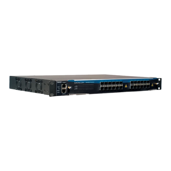
Chapter 2. DM4001 Chassis 2.1. Overview The DM4001 chassis is compatible with all interface boards of the DM4000 series, allowing a Stand Alone versions of all Interface Boards. Its Backplane interface allow Non-blocking Wire Speed data of all Interface Boards connected. -
Page 13: System Status Leds
The System Status LEDs on the front panel can be used to monitor system activity. Following Figure shows where the leds are located and the table below indicates the system status acording to each led’s condition. Figure 2-3. DM4001 Chassis - Front Panel Leds Table 2-1. System LEDs DM4001 Chassis CONDITION... -
Page 14: Rear Panel Description
The pin-out of both console and outband management ports are shown in the next figure. Figure 2-4. Double RJ-45 Table 2-2. Interface Pinout Management Port RJ-45 Signal 4,5,7,8 RJ-45 Serial Port 2.5. Rear Panel Description The Rear panel of the DM4001 chassis has two DC input power 36-72V range for power supply the equipment. -
Page 15: Dm4004 Chassis
Chapter 3. DM4004 Chassis 3.1. Overview The DM4004 chassis is compatible with all MPUs and interface boards of the DM4000 series. It has a Backplane that can handle up to 384Gbp/s of Non-blocking data. It has four interface Board slots, two MPU SLOTs, two Multipurpose Slots and a FAN Slot. -
Page 16: Front Panel Description
Chapter 3. DM4004 Chassis 3.2. Front Panel Description In the DM4004 Chassis front panel are located the Main input power in Chassis, it is a DC input of 48V Nominal. Figure 3-2. DM4004 Chassis - Front Panel 3.3. Rear Panel Description Figure 3-3. -
Page 17: Dm4008 Chassis
Chapter 4. DM4008 Chassis 4.1. Overview The DM4008 chassis is compatible with all MPUs and interface boards of the DM4000 series. It has a Backplane that can handle up to 384Gbp/s of Non-blocking data. It has eight interface Board slots, two MPU SLOTs, two Multipurpose Slots and a FAN Slot. -
Page 18: Front Panel Description
Chapter 4. DM4008 Chassis 4.2. Front Panel Description In the DM4008 Chassis front panel are located the Main input power in Chassis. It is a DC input of 48V Nominal. Figure 4-2. DM4008 Chassis - Front Panel... - Page 19 Chapter 4. DM4008 Chassis 4.3. Rear Panel Description Figure 4-3. DM4008 Chassis - Rear Panel...
-
Page 20: Dm4000 Mpu192
Chapter 5. DM4000 MPU192 5.1. Overview The DM4000 MPU192 is a hot-swappable Switch Fabric capable of handling 192Gbp/s of Non-blocking Data ( 96 ports Gigabit Ethernet ). It is compatible with DM4004 and DM4008 chassis. In the DM4004 chassis it can handle up to 24 Gigabit ports per interface board at a non blocking configuration, in the DM4008 it can handle up to 12 Gigabit ethernet ports per interface Board. -
Page 21: Front Panel Description
Chapter 5. DM4000 MPU192 5.2. Front Panel Description In the DM4000 MPU192 front panel is located the System Status Leds, Consoles and Ethernet Outband Management Ports. Figure 5-2. DM4000 MPU192 - Front Panel 5.3. System Led Status The DM4000 MPU192 has 9 system status Leds Monitoring CPU utilization, Ethernet Outband, system fails and Hot MPU Status. -
Page 22: Console And Ethernet Outband Management Ports
Chapter 5. DM4000 MPU192 CONDITION STATUS Indicates that a 100M inactive. Link Act ON/Blinking Connection established. No connection established. 5.4. Console and Ethernet Outband Management Ports The DM4000 MPU192 contains three RJ-45 connectors on its front panel. One for Outband Management a console port and a AUX console Port for future implementation. - Page 23 Chapter 5. DM4000 MPU192 AUX Port...
-
Page 24: Dm4000 Mpu384
Chapter 6. DM4000 MPU384 6.1. Overview The DM4000 MPU384 is a hot-swappable Switch Fabric capable of handling 384Gbp/s of Non-blocking Data ( 192 ports Gigabit Ethernet ). It is compatible with DM4004 and DM4008 chassis, In the DM4004 chassis it can handle up to 48 Gigabit ports per interface board at a non blocking configuration, in the DM4008 it can handle up to 24 Gigabit ethernet ports per interface Board. -
Page 25: Front Panel Description
Chapter 6. DM4000 MPU384 6.2. Front Panel Description In the DM4000 MPU384 front panel is located the System Status Leds, Consoles and Ethernet Outband Management Ports. Figure 6-2. DM4000 MPU384 - Front Panel 6.3. System Led Status The DM4000 MPU384 has 9 system status Leds Monitoring CPU utilization, Ethernet Outband, system fails and Hot MPU Status. -
Page 26: Console And Ethernet Outband Management Ports
Chapter 6. DM4000 MPU384 CONDITION STATUS Indicates that a 100M inactive. Link Act ON/Blinking Connection established. No connection established. 6.4. Console and Ethernet Outband Management Ports The DM4000 MPU384 contains three RJ-45 connectors on its front panel. One for Outband Management a console port and a AUX console Port for future implementation. - Page 27 Chapter 6. DM4000 MPU384 AUX Port...
-
Page 28: Dm4000 Eth24Gx-Mpls
Chapter 7. DM4000 ETH24GX-MPLS 7.1. Overview The DM4000 ETH24GX-MPLS is a Non-blocking 24 port SFP interface board compatible with DM4001, DM4004 and DM4008 chassis. The DM4000 ETH24GX-MPLS can handle up to 35.714.285 packets per second supporting 9600 Bytes Jumbo frames and has an internal 256MBytes Switching Memory reaching wire speed operation. -
Page 29: System Status Leds
Chapter 7. DM4000 ETH24GX-MPLS Figure 7-2. DM4000 ETH24GX-MPLS - Front Panel 7.3. System Status Leds The DM4000 ETH24GX-MPLS has the Following port Led Status. Figure 7-3. DM4000 ETH24GX-MPLS - Front Panel Leds Table 7-1. Port LEDs ETH24GX-MPLS CONDITION STATUS Link/Act ON/Blinking Connection established. -
Page 30: Hardware
Chapter 7. DM4000 ETH24GX-MPLS 7.4.2. Hardware Table 7-2. Hardware DM4000 ETH24GX-MPLS Switch L2 Wire Speed Router 3 Wire Speed L2-L4 MPLS LER/LSR Ports 24 x 1000Base-X (SFP) Packet Buffer 128 MB Switch Fabric (intern) 48 Gbit/s Flash 64 MB SDRAM 256 MB MAC adress table 512K*... -
Page 31: Dm4000 Eth12Gx-Mpls
Chapter 8. DM4000 ETH12GX-MPLS 8.1. Overview The DM4000 ETH12GX-MPLS is a Non-blocking 12 port SFP interface board compatible with DM4001, DM4004 and DM4008 chassis. The DM4000 ETH12GX-MPLS can handle up to 17.857.142 packets per second supporting 9600 Bytes Jumbo frames and has an internal 128MBytes Switching Memory reaching wire speed operation. -
Page 32: System Status Leds
Chapter 8. DM4000 ETH12GX-MPLS Figure 8-2. DM4000 ETH12GX-MPLS - Front Panel 8.3. System Status Leds The DM4000 ETH12GX-MPLS has the Following port Led Status. Figure 8-3. DM4000 ETH12GX-MPLS - Front Panel Leds Table 8-1. Port LEDs ETH12GX-MPLS CONDITION STATUS Link/Act ON/Blinking Connection established. -
Page 33: Software And Hardware Features
Chapter 8. DM4000 ETH12GX-MPLS 8.4. Software and Hardware Features 8.4.1. Software The software is available in separated guide. 8.4.2. Hardware Table 8-2. Hardware DM4000 ETH12GX-MPLS Switch L2 Wire Speed Router 3 Wire Speed L2-L4 MPLS LER/LSR Ports 12 x 1000Base-X (SFP) Packet Buffer 128MB Switch Fabric (intern) -
Page 34: Dm4000 Eth12Gx+1X10Gx-Mpls
9.1. Overview The DM4000 ETH12GX+1x10GX-MPLS is a Non-blocking 12 port SFP plus one 10 Gigabit XFP port interface board compatible with DM4001, DM4004 and DM4008 chassis. The DM4000 ETH12GX+1x10GX-MPLS can handle up to 32.738.095 packets per second supporting 9600 Bytes Jumbo frames and has an internal 256MBytes Switching Memory reaching wire speed oper- ation. -
Page 35: System Status Leds
Chapter 9. DM4000 ETH12GX+1x10GX-MPLS Leds. Figure 9-2. DM4000 ETH12GX+1x10GX-MPLS - Front Panel 9.3. System Status Leds The DM4000 ETH12GX+1x10GX-MPLS has the Following port Led Status. Figure 9-3. DM4000 ETH12GX+1x10GX-MPLS - Front Panel Leds Table 9-1. Port LEDs ETH12GX+1x10GX-MPLS CONDITION STATUS Link/Act ON/Blinking Connection established. -
Page 36: Software And Hardware Features
Chapter 9. DM4000 ETH12GX+1x10GX-MPLS 9.4. Software and Hardware Features 9.4.1. Software The software is available in separated guide. 9.4.2. Hardware Table 9-2. Hardware DM4000 ETH12GX+1x10GX-MPLS Switch L2 Wire Speed Router 3 Wire Speed L2-L4 MPLS LER/LSR Ports 12 x 1000Base-X (SFP) + 1 x 10G (XFP) Packet Buffer 128 MB Switch Fabric (intern) -
Page 37: Dm4000 Eth2X10Gx-Mpls
10.1. Overview The DM4000 ETH2x10GX-MPLS is a Non-blocking two 10 Gigabit XFP port interface board compatible with DM4001, DM4004 and DM4008 chassis. The DM4000 ETH2x10GX-MPLS can handle up to 29.761.904 packets per second supporting 9600 Bytes Jumbo frames and has an internal 256MBytes Switching Memory reaching wire speed operation. -
Page 38: System Status Leds
Chapter 10. DM4000 ETH2x10GX-MPLS Figure 10-2. DM4000 ETH2x10GX - Front Panel 10.3. System Status Leds The DM4000 ETH2x10GX-MPLS has the Following port Led Status. Figure 10-3. DM4000 ETH2x10GX - Front Panel Leds Table 10-1. Port LEDs ETH2x10GX CONDITION STATUS Link/Act ON/Blinking Connection established. -
Page 39: Hardware
Chapter 10. DM4000 ETH2x10GX-MPLS 10.4.2. Hardware Table 10-2. Hardware DM4000 ETH2x10GX Switch L2 Wire Speed Router 3 Wire Speed L2-L4 MPLS LER/LSR Ports 2 x 10G (XFP) Packet Buffer 128 MB Switch Fabric (intern) 40 Gbit/s Flash 64 MB SDRAM 256 MB MAC adress table 512K*... -
Page 40: Dm4000 Eth24Gt
11.1. Overview The DM4000 ETH24GT is a non-blocking 24 port 1000/100/10 Mbps interface board compatible with DM4001, DM4004 and DM4008 chassis. The DM4000 ETH24GT can handle up to 35.714.285 packets per second supporting 9500 Bytes Jumbo frames reaching wire speed operation. -
Page 41: System Status Leds
Chapter 11. DM4000 ETH24GT Figure 11-2. DM4000 ETH24GT - Front Panel 11.3. System Status Leds The DM4000 ETH24GT has the following Port Status LEDs: Table 11-1. Port LEDs ETH24GT CONDITION STATUS Link/Act ON/Blinking Connection established. Blinking indicates port activity. No connection established. 10/100/1000 Orange Indicates that a 10/100Mbps connection was... - Page 42 Chapter 11. DM4000 ETH24GT MPLS Not Available 24 ports Ports 24 x 10/100/1000 Base-TX Packet Buffer 2 MB Switch Fabric (intern) 48 Gbit/s Flash 64 MB SDRAM 256 MB MAC adress table L3 hosts (IPv4) L3 hosts (IPv6) L3 Routes (IPv4) L3 Routes (IPv6) L2 Multicast groups L3 Multicast groups (Ipv4)
-
Page 43: Dm4000 Eth48Gt
12.1. Overview The DM4000 ETH48GT is a non-blocking 48 port 1000/100/10 Mbps interface board compatible with DM4001, DM4004 and DM4008 chassis. The DM4000 ETH48GT can handle up to 71.428.571 packets per second supporting 9500 Bytes Jumbo frames reaching wire speed operation. -
Page 44: System Status Leds
Chapter 12. DM4000 ETH48GT Figure 12-2. DM4000 ETH48GT- Front Panel 12.3. System Status Leds The DM4000 ETH48GT has the following Port Status LEDs: Table 12-1. Port LEDs ETH48GT CONDITION STATUS Link/Act ON/Blinking Connection established. Blinking indicates port activity. No connection established. 10/100/1000 Orange Indicates that a 10/100Mbps connection was... - Page 45 Chapter 12. DM4000 ETH48GT MPLS LER/LSR 48 ports Ports 48 x 10/100/1000 Base-TX Packet Buffer 2 MB Switch Fabric (intern) 96 Gbit/s Flash 64 MB SDRAM 256 MB MAC adress table L3 hosts (IPv4) L3 hosts (IPv6) L3 Routes (IPv4) L3 Routes (IPv6) L2 Multicast groups L3 Multicast groups (Ipv4)
-
Page 46: Fan Board
Chapter 13. Fan Board 13.1. Description Fan’s are used to avoid a highly temperature that could be compromise Switch functioning. Fan board can be replaced while the switch is active - hot swappable. Warning Don’t put objects near the fan board exit and control the environment temperature. -
Page 47: Installation Guide
Chapter 14. Installation Guide 14.1. Installing the Switch in a Rack The switch can be installed in a 19" rack. The brackets used to fix the device already come attached to the switch. To install the switch in a rack, use the following procedure and refer to the figure below: Figure 14-1. -
Page 48: Installing The Fan Board In Switch
Chapter 14. Installation Guide Figure 14-2. AC/DC Power Suply Connector 14.3. Installing the Fan Board in Switch Figure 14-3. Fan Board Installation 14.4. Inserting the Interface Board in Switch Follow the following pictures to a correct insertion of a DM4000 interface Board to the DM4004 or DM4008 chassis. -
Page 49: Sfp Module
Chapter 14. Installation Guide Figure 14-4. Inserting the Interface Board in Switch According the figure, the installation sequence is: 1. Brackets should be located to rabbet in chassis 2. Brackets should be located after the board 3. Press the brackets to chassis 14.5. -
Page 50: Removing Sfp Modules
Chapter 14. Installation Guide 1. Insert the SFP transceiver into one of the four switch module bays. There’s only one orientation that the module can be plugged. The optical connector should face outward. The slot connector should face down for the upper bays, and up for the lower bays. 2. -
Page 51: Removing A Sfp Module
Chapter 14. Installation Guide 14.5.2. Removing SFP Modules Removing modules follow the order below: Warning Before remove fiber verify if are signals of each fiber should be connected en which module. Figure 14-7. Removing a SFP module 1. Remove the fibers 2. -
Page 52: Technical Specifications
FAN Board: 3A Fastons: 20A each, total 40A 15.3. Dimensions Height 240 mm (DM4004), 400mm (DM4008) and 44mm (DM4001) Width 440mm without L brackets to install in 19” rack 483mm with L brackets to install in 19 ” rack Depth... -
Page 53: Weight
Chapter 15. Technical Specifications 15.4. Weight Table 15-1. Chassis Chassis Kilograms (KG) Pounds (lbs) DM4001 2.940 6.482 DM4004 8.190 18.079 DM4008 11.410 25.188 Table 15-2. MPUs Kilograms (KG) Pounds (lbs) MPU192 0.980 2.163 MPU384 0.980 2.163 Table 15-3. Interface Boards... -
Page 54: Norms And Certifications
Chapter 16. Norms and Certifications 16.1. Norms Classification Norms Description IEEE 802.3 10Base-T 802.3u 100Base-TX and 100Base-FX 802.3z 1000Base-SX 802.3ab 1000Base-T 802.3x Flow Control 802.3ac Extension for VLAN Tagging 802.1D Bridging 802.1Q Virtual LAN 802.1w Rapid Spanning Tree 802.3ad Link Aggregation 802.1p Priority Support 802.1x... -
Page 55: A.1. Pins
Appendix A. DB9 A.1. Pins Figure A-1. DB9 Pins Order Table A-1. RJ45-DB9 Pins Order RJ45 Nomenclature Nomenclature...
Need help?
Do you have a question about the DM4001 and is the answer not in the manual?
Questions and answers