Table of Contents
Advertisement
Quick Links
Download this manual
See also:
Quick Manual
148 OLD CONCORD TURNPIKE BARRINGTON, NH 03825 USA TEL (603) 868-5720
E-Mail:sales@seafrost.com
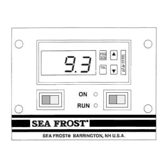
ELECTRONIC THERMOSTAT AND THERMOMETER
• The Sea Frost ETT's (Electronic Thermostat/Thermometer) accurate
operating settings and the programmable differential increases
efficiency. In comparison, mechanical controls tend to over run the
desired temperature range and must be set colder, running the
compressor longer, to maintain the proper average temperature.
• The ETT will operate any Sea Frost electrical compressor system, AC
or DC.
• The ETT always shows cabinet temperature, and will display in
Centigrade or Fahrenheit.
• Accurate numerical setting of operating temperatures and differential
makes set up and temperature adjustment easy.
FAX (603) 868-1040
1-800-435-6708
www.seafrost.com
Advertisement
Table of Contents

Subscribe to Our Youtube Channel
Related Manuals for Sea Frost ETT’s


Summary of Contents for Sea Frost ETT’s
- Page 1 • The ETT will operate any Sea Frost electrical compressor system, AC or DC. • The ETT always shows cabinet temperature, and will display in Centigrade or Fahrenheit.
- Page 2 INSTALLATION AND OPERATION MANUAL OPERATION The Sea Frost Electronic Thermostat and Thermometer (ETT) is an electronic device using two probes installed in the refrigerated space. One probe is sensing the cabinet temperature, which is displayed. The other probe controls the compressor operation by measuring the temperature of a cold plate.
- Page 3 set cut out temperature the RUN indicator light will go off with the compressor. The ON indicator light will remain lit indicating a standby or ready to run mode. To display temperature only turn off the right ON/RUN switch. To turn off both the temperature readout and compressor the left switch may be used however when turning it back on the compressor will start immediately.
- Page 4 Make several small setting changes over a period of several days to determine the proper setting. CHANGING THE TEMPERATURE To lower or raise the box temperature, hold the SEL button until the ST-1 appears. Release the button and the cut out temperature will flash. Use the up and down arrows to change the temperature.
- Page 5 WIRE ROUTING and CONNECTING The blue cat-5 cable provides power and signal for the ETT. It connects at the compressor. The RJ-45 connector on this cable plugs into the RJ-45 port on the Module PCB board. Make certain the plug is clean, and that the plug has not been damaged when routing through the boat, before plugging it in.
- Page 6 near a front opening door or too close to a cold plate. Mount the probe bulb with two nylon straps or self stick pads and tie wraps provided. Do not drill and screw into a vacuum panel box! Secure the wires neatly using cable ties, self-stick pads, and proper yacht construction wiring practices.
- Page 7 SEA FROST ELECTRONIC THERMOSTAT AND THERMOMETER DRILL (4) HOLES 3/32" FOR #6 SCREWS. Control Panel Head Sensor Probes (1-with red band, 1-without red band) Cat 5 cable with RJ 45 Connector INSTALLATION KIT #6 x 1/2" flat head screws for mounting panel #6 x 1/2"...
Need help?
Do you have a question about the ETT’s and is the answer not in the manual?
Questions and answers