Table of Contents
Advertisement
Quick Links
Advertisement
Table of Contents

Related Manuals for Kontron CRTtoLCD-7

Summary of Contents for Kontron CRTtoLCD-7
- Page 1 Flat Panel Controller CRTtoLCD-7...
-
Page 2: Table Of Contents
CRTtoLCD7 User´s Guide Contents GENERAL INFORMATION AND IMPORTANT NOTES ................. 2 User Information..................2 Trademarks ....................2 General ....................2 Warranty....................2 INTRODUCTION......................3 TECHNICAL INFORMATION SUMMARY ..................3 CONFIGURATION......................5 Panel Vcc configuration JP7000 ..............5 Backlight adjust configuration JP7001 ............5 Backlight Mode configuration JP7002 ............5 Backlight ON/OFF configuration JP7003 ............6 CONNECTORS ........................ - Page 3 CRTtoLCD7 User´s Guide 5.2.7 Input Select - PIP ver. Position ..............18 5.2.8 Input Select - Swap Main & PIP ..............18 Image Adjustments .................. 19 5.3.1 Image Adjustments - Auto Adjust ..............19 5.3.2 Image Adjustments - Clock................. 19 5.3.3 Image Adjustments - Phase................
- Page 4 CRTtoLCD7 User´s Guide 5.9.5 Scaling Adjustment – Ver. Pan ..............34 5.10 System Settings ..................35 5.10.1 System Settings – OSD Timeout..............35 5.10.2 System Settings – OSD Hor. Pos..............35 5.10.3 System Settings – OSD Ver. Pos..............35 5.10.4 System Settings –...
- Page 5 CRTtoLCD7 User´s Guide 10. TECHNICAL SUPPORT .....................55 11. REVISION HISTORY......................56 Contents...
-
Page 6: General Information And Important Notes
User Information Copyright 2007 by Kontron Embedded Modules GmbH. In this document Kontron Embedded Modules GmbH will also be referred to by the short form “Kontron Embedded Modules”. The information in this document has been carefully checked and is believed to be accurate and reliable. -
Page 7: General Information And Important Notes
During the warranty period, Kontron Embedded Modules will, at its option, either repair or replace products which prove to be defective. For warranty service or repair, the product must be returned to a service facility designated by Kontron Embedded Modules. -
Page 8: Introduction
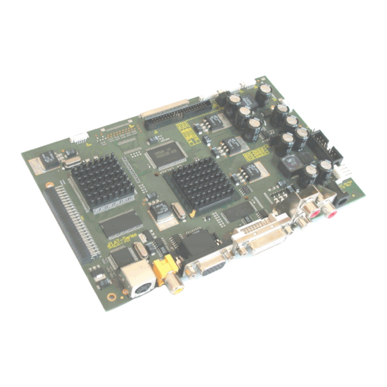
TVtoLCD User´s Guide Introduction The CRTtoLCD-7 is a highly integrated TFT panel interface controller, which allows an easy adaptation of standard video input sources like S-video, composite video, DVI or analog RGB to a digital TFT panel. The CRTtoLCD-7 only needs one single 12V power supply and incorporates all needed functionality to build up a full featured TFT monitor. - Page 9 TVtoLCD User´s Guide RealColor Technology - Color filtering in YUV domain - Digital brightness, contrast, hue and saturation control for analog, digital and video inputs - Proprietary flesh tone adjustment Operating Modes - Frame rate conversion and scaling of images - Bypass mode with no filtering and/or frame buffering - 1:1 centering - De-interlaced zoom...
-
Page 10: Configuration
TVtoLCD User´s Guide Configuration Panel Vcc configuration JP7000 Use JP700 to control Panel Vcc Connector Double Row 2,54 mm, 3 Contacts, Gold plated Case/Size : Vertical, Through Hole 1 2 3 open JP7000 O O O 3,3V Never default unplug/r eplug this while in use! -
Page 11: Backlight On/Off Configuration Jp7003
TVtoLCD User´s Guide Backlight ON/OFF configuration JP7003 Use JP7003 to control polarity of backlight ON/OFF Connector Double Row 2,54 mm, 3 Contacts, Gold plated Case/Size : Vertical, Through Hole 1 2 3 Delivery Default JP7003 1-2 closed O O O Never unplug/replug this while in... -
Page 12: Vga/Rgb Analog Input Cn300
TVtoLCD User´s Guide VGA/RGB analog Input CN300 High Density Sub-D-Connector 15 Contacts, Receptacle Case/Size : Right Angle, Through Hole Name Description Analog input red GREEN Analog Input Green BLUE Analog Input Blue Not Connected Analog Ground Analog Ground Red Analog Ground Green Analog Ground Blue DDC_5V +5V Power Supply from Video Card... -
Page 13: Dvi Input Connector Cn6
TVtoLCD User´s Guide DVI input connector CN6 This input supports the connection of DVI capable video cards and supports resolutions from 640x480 up to 1920x1200. Connector Double Row 2,54 mm, 10 Contacts, Gold plated Case/Size : Vertical, Through Hole Description Name Name Description... -
Page 14: Composite Video Input Cn13
TVtoLCD User´s Guide Composite video input CN13 This input converts NTSC, PAL or SECAM in composite video to digitized component video. Chinch Connector, Right Angle, Yellow Name Description CN13 Power Ground CVBS CVBS Video Signal IR input CN1001 This input connects a IR Receiver with the board 3 Contact Connector, Single Row, Straight, through hole Name Description... -
Page 15: Osd Keypad Connector Cn1003
TVtoLCD User´s Guide 4.10 OSD keypad connector CN1003 Connector: Molex 53261-1471 Matching Connector: Molex 51021-1400 Connector Single Row, 14 contacts, Case/Size : Right Angle, 1,25mm Pitch Name Description LED2 LED Red (3.3V output) LED1 LED Green (3.3V output) Key Power Ground Key Button (POWER) Key Power Ground Key Button (Menu) -
Page 16: Jili40-Interface Cn800
TVtoLCD User´s Guide 4.12 JILI40-Interface CN800 All flat screen signals are LVDS compatible Connector Double Row 2mm, 40 Contacts, Gold plated Case/Size : Straight, Through Hole Description Name Name Description Enables Backlight Enables Backlight BLON# BLON# Backlight Adjust BLADJ STX3+ Even Receiver Signal(+) (R2IN 3+) +12V +12V... -
Page 17: Jili30-Interface Cn7000
TVtoLCD User´s Guide 4.13 JILI30-Interface CN7000 All JILI (JUMPtec Intelligent LVDS Interface ) signals are LVDS compatible. Fine Wire, 30 Contacts, single row, Right Angle, Series : JAE-FI- X30H Description Name Name Description Odd Receiver Signal(-) (R1IN 0-) FTX0- FTX0+ Odd Receiver Signal(+) (R1IN 0+) Odd Receiver Signal(-) (R1IN 1-) FTX1-... -
Page 18: Flex32 Cn7003
TVtoLCD User´s Guide 4.14 FLEX32 CN7003 This connector directly matches through an interface cable for 31/41 pin VGA/SVGA TFT interface. All flat screen signals are LVTTL compatible (3.3V ) Flatfoil Connector 32 Contacts, Right Angle, Bottom Contact Case/Size : 0,5mm Pitch, Series : 6210 / ZIF Description Name Name... -
Page 19: Backlight Connector Cn7002
TVtoLCD User´s Guide 4.16 Backlight Connector CN7002 Connector: Molex 53261-0790 Matching Connector: Molex 51021-0700 Connector Single Row, 7 Contacts, Case/Size : Right Angle, 1,25mm Pitch Name Description Not connected BKLTADJ analog 0V to +5V or 0V to +12V (refer JP7001) Power Ground Backlight power supply Typ. -
Page 20: Adc Input Connector Cn1000 (Light Sensor Input)
With the OSD ( On Screen Display ) you can modify the settings and control the special features of the CRTtoLCD-7. The OSD uses a number of menus for making changes and turning the special features on or off. The configuration can be done via the OSD-keypad (OSD-Panel-Kit). -
Page 21: Input Select
TVtoLCD User´s Guide Input Select In the “Input Select” menu the sources for the “Main Picture Channel” and for the “PIP” (picture in picture) can be selected. 5.2.1 Input Select - Main Picture Channel For the “Main Picture Channel” every possible input source can be selected (VGA, Component, DVI, S-Video, Composite Video, Tuner). -
Page 22: Input Select - Pip Mode
TVtoLCD User´s Guide 5.2.3 Input Select - PIP Mode When the “PIP Mode” is activated all options for the “PIP” are available in the menu. There are 2 possible settings for the “PIP”. When the “Picture in Picture”-Mode is selected the “PIP”-video signal will be shown in a window. -
Page 23: Input Select - Pip Hor. Position
TVtoLCD User´s Guide 5.2.6 Input Select - PIP hor. Position The horizontal position of the “PIP” can be set from 0 (left margin) to 100 (right margin). figure 7: Input Select - PIP hor. Position 5.2.7 Input Select - PIP ver. Position The vertical position of the “PIP”... -
Page 24: Image Adjustments
TVtoLCD User´s Guide Image Adjustments In this section several adjustments of the image position and timing for the “Main Picture Channel”can be made. The settings made in this section don´t affect the “PIP”. 5.3.1 Image Adjustments - Auto Adjust When the “Auto Adjust” function is selected the system tries to adjust the image (clock, phase, bandwith and position) automatically. -
Page 25: Image Adjustments - Phase
TVtoLCD User´s Guide 5.3.3 Image Adjustments - Phase The phase of the display can be set for the “Main Picture Channel” here. figure 12: Image Adjustments -Phase 5.3.4 Image Adjustments - Bandwith The bandwith of the display can be set for the “Main Picture Channel”... -
Page 26: Image Adjustments - Ver. Position
TVtoLCD User´s Guide 5.3.6 Image Adjustments - Ver. Position The “vertical Position” of the picture can be set for the “Main Picture Channel” here. figure 15: Image Adjustments –Ver. Position Color Adjustment In this section the color of the picture can be optimized for the “Main Picture Channel”. The settings made in this section don´t affect the “PIP”... -
Page 27: Color Adjustment - Contrast
TVtoLCD User´s Guide 5.4.2 Color Adjustment – Contrast The contrast level for the “Main Picture Channel” is set here. The range of adjustment is 0 (very low contrast) to 100 (very high contrast). The default vaule is 50. figure 17: Color Adjustment - Contrast 5.4.3 Color Adjustment –... -
Page 28: Color Adjustment - Fleshtone
TVtoLCD User´s Guide 5.4.5 Color Adjustment – Fleshtone The “Fleshtone” for the “Main Picture Channel” can be selected here. The range of adjustment is 0 to 3. The dafault vaule is 0. figure 20: Color Adjustment - Fleshtone 5.4.6 Color Adjustment – Backlight The backlight brightness for the “Main Picture Channel”... -
Page 29: Advanced Color Adjustment
TVtoLCD User´s Guide Advanced Color Adjustment The “Advanced Color Adjustment” comprises gamma, color space and the color temperature settings. The rates for the 3 fundamental colors can also be set within the “Advanced Color Adjustment”-menu. The “Advanced Color Adjustment” only effects the “Main Picture Channel”. -
Page 30: Color Adjustment - Advanced - Color Temp
TVtoLCD User´s Guide 5.5.3 Color Adjustment – Advanced – Color Temp. To adjust the “Color Temperature” 6 different values can be selected for the “Main Picture Channel”(4200K, 5000K, 5400K, 6500K, 7500K, 9300K). When the “Color Temperature” is set to “User” the color temperature is adjusted by the 3 fundamental colors. -
Page 31: Color Adjustment - Advanced - Blue
TVtoLCD User´s Guide 5.5.6 Color Adjustment – Advanced – Blue The rate of red for the “Main Picture Channel” is set here. The range of adjustment is 0 to 255. The default value is 255. figure 29: Color Adjustment – Advanced - Blue Video Settings The “Video Settings”... -
Page 32: Video Settings - Sharpness
TVtoLCD User´s Guide 5.6.2 Video Settings – Sharpness The “Sharpness” of the video signal is set here. The range of adjustment is -15 to 29. The dafault vaule is 0. figure 31: Video Settings – Sharpness 5.6.3 Video Settings – Film Mode The “Film Mode”... -
Page 33: Video Settings - Mpeg Processing
TVtoLCD User´s Guide 5.6.5 Video Settings – Mpeg Processing The level for the “Mpeg Processing” is set here. The range of adjustment is 0 to 15. The default vaulue is 0. figure 34: Video Settings – Mpeg Processing Video Settings – Decoder Settings In this section several settings for the “Video Decoder”... -
Page 34: Decoder Settings - Video Contrast
TVtoLCD User´s Guide 5.7.2 Decoder Settings – Video Contrast The level for the “Video Contrast” is set here. The range of adjustment is 0 to 100. The default value is 50. figure 37: Decoder Settings – Video Contrast 5.7.3 Decoder Settings – Video Saturation The level for the “Video Saturation”... -
Page 35: Decoder Settings - Video Sharpness
TVtoLCD User´s Guide 5.7.5 Decoder Settings – Video Sharpness The level for the “Video Sharpness” is set here. The range of adjustment is 0 to 7. The default vaulue is 0. figure 40: Decoder Settings – Video Sharpness Video Settings – CRTtoLCD7 multimedia 5.8.1 Video Settings –... -
Page 36: Video Settings - Enhancer (Crttolcd7 Multimedia)
TVtoLCD User´s Guide 5.8.3 Video Settings – Enhancer (CRTtoLCD7 multimedia) The “Enhancer” is configured here. It can be switched either on or off. As default the “Enhancer” is turned on. figure 43: Video Settings – Enhancer (CRTtoLCD7 multimedia) 5.8.4 Video Settings – Sharpness (CRTtoLCD7 multimedia) The level for the “Sharpness”... -
Page 37: Video Settings - Noise Reduction (Crttolcd7 Multimedia)
TVtoLCD User´s Guide 5.8.6 Video Settings – Noise Reduction (CRTtoLCD7 multimedia) The level for the “Noise Reduction” is set here. Three different levels of “Noise Reduction” can be selected (Low, Medium, High) or it can be set to automatic “Noise Reduction”. The default value is “Auto”. -
Page 38: Scaling Adjustment
TVtoLCD User´s Guide Scaling Adjustment In this section the picture of the “Main Picture Channel” can be scaled. 5.9.1 Scaling Adjustment – Scaling Mode The “Scaling Mode” for the “Main Picture Channel” is set here. As default the “Main Picture Channel”... -
Page 39: Scaling Adjustment - Zoom
TVtoLCD User´s Guide 5.9.3 Scaling Adjustment – Zoom In this section the “Zoom” for the picture of the “Main Picture Channel” is set. The level of adjustment is 0 to 302. The dafault value is 0 (no zoom). figure 50: Scaling Adjustment – Zoom 5.9.4 Scaling Adjustment –... -
Page 40: System Settings
TVtoLCD User´s Guide 5.10 System Settings In this section some general settings for the OSD can be set. 5.10.1 System Settings – OSD Timeout The “OSD Timeout” is set in this section. The default value for the timout is 30 seconds. The level of adjustment is 0 to 60 seconds in 5 second steps. -
Page 41: System Settings - Osd Blend
TVtoLCD User´s Guide 5.10.4 System Settings – OSD Blend In this section the level of transperency of the OSD is set. The level of adjustment is 0 (solid OSD) to 15 (clear OSD). The default value for the “OSD Blend” is 3. figure 56: System Settings –... -
Page 42: System Settings - Reset To Default
TVtoLCD User´s Guide 5.10.7 System Settings – Reset to Default In this section the OSD can be resetted to factory defaults. figure 59: System Settings – Reset to Default 5.11 Audio Settings Several audio settings for the TvtoLCD can be set in this section. 5.11.1 Volume The “Volume”... -
Page 43: Surround
TVtoLCD User´s Guide 5.11.3 Surround The surround mode is selected in this section. As defalut the surround mode is turned off. There are two different possible surround modes (normal and spatial). figure 62: Audio Settings - Surround 5.11.4 Loudness The level of “Loudness” is set in this section. The loudness can be set from 0 (default) to 68 (+17dB). -
Page 44: Mode
TVtoLCD User´s Guide 5.11.6 Mode In this section three different audio modes can be selected. The user can choose between “Mono”, “Stereo” and “SAP” (second audio source). By default the audio mode is set to “Stereo”. figure 65: Audio Settings - Mode 5.11.7 Equalizer In this section the “Equalizer”... -
Page 45: Tv - Program
TVtoLCD User´s Guide 5.12 TV Several settings for the TV-Tuner can be set in this section. 5.12.1 TV - Program In the “Program” section the user can switch between all saved programs. figure 67: TV – Program 5.12.2 TV - Channel In this section the channels can be scanned manually. -
Page 46: Tv - Frequency
TVtoLCD User´s Guide 5.12.3 TV - Frequency In this section the “Frequency” can be scanned manually. When a “Frequency” needs to be saved it can be added to the list of saved programs by selecting “Favourites” (see chapter 5.12.6) figure 69: TV - Frequency 5.12.4 TV - System In this section the different PAL norms are selected. -
Page 47: Tv - Favorites
TVtoLCD User´s Guide 5.12.6 TV – Favorites In the “Favourites” section the user can add new programs to the programlist or update the list of favourite programs with all recently found stations. The favourite programs list can also be edited (see chapter 5.12.7). figure 72: TV –... -
Page 48: Radio
TVtoLCD User´s Guide 5.13 Radio In this section the radio can be set up. When the TV-Tuner is activated the radio settings are not available. In this menu the radio can be turned on or off. When the radio is activated the TV-Tuner settings are not available. -
Page 49: Radio - Scan Station
TVtoLCD User´s Guide 5.13.3 Radio - Scan Station In the “Scan Station” section the user can scan either for the next or for the previous radio- station automatically. figure 78: Radio – Scan Station 5.13.4 Radio - Save Station In this section the radio-stations can be saved so they are available in the “Station”... -
Page 50: Serial Osd
TVtoLCD User´s Guide Serial OSD Settings (connection and basic information) Connect / Disconnect Let you establish or relieve connection to the CRTtoLCD-7 Auto update Automatically refreshes OSD settings Device Information Shows information about the current Firmware, the Panelfile, physically resolution of the panel and let you see information about the detected input format. -
Page 51: Picture In Picture
TVtoLCD User´s Guide Picture in Picture (Select view, size and position of the PIP) Pip Mode Choose appearance of PIP-Window Pip Size Select size of PIP Pip Horizontal Position Adjust horizontal position of PIP- Window in percent Pip Vertical Position Adjust horizontal position of PIP- Window in percent VGA Adjustment... -
Page 52: Color Adjustment
TVtoLCD User´s Guide Color Adjustment (Basic color settings for each main input) Adjustable are all necessary color settings. These settings can be adjusted independently for each main input. Advanced Color (Advanced color settings for all inputs) Gamma Correction Select default Gamma settings Color Temperature Select predefined or user defined color temperature settings... -
Page 53: Video
TVtoLCD User´s Guide Video (Define video input depending parameters for video processing) External Deinterlacer Switch external deinterlacer (On/Off) Motion Processing Select motion processing Film Mode Switch film mode (On/Off) Enhancer Switch enhancer (On/Off) DCDi Switch DCDi (On/Off) Noise Reduction Select noise reduction Cross Color Switch cross color (On/Off) Sharpness... -
Page 54: Audio
TVtoLCD User´s Guide Audio * (Audio mode and volume settings) Volume Adjust master volume Balance Adjust balance between left and right Surround Select Surround mode. If surround mode was selected, the surround effect efficiency can be adjust Mode Select audio output mode Pseudo Stereo Adjust efficiency of pseudo stereo effect... -
Page 55: Osd Settings
TVtoLCD User´s Guide 6.11 TV (Set default program or channel for the TV-Tuner) Program Select program for the TV-Tuner Channel Select channel *only activated when used in combination with TV-Tuner-Extension 6.12 OSD Settings Horizontal / Vertical Position Set the position of the OSD-Menu Timer Adjust time till the OSD-Menu will be closed if no changes were made... -
Page 56: Technical Specifications
Typical supply voltage + 12,0 V DC Absolute Maximum supply voltage + 12.6 V DC Typical Input current at 25˚C: CRTtoLCD-7- OSD-keypad, input signal SXGA: 680mA CRTtoLCD-7- OSD-keypad, power down: 380mA Supply voltage ripple: 100 mV peak to peak 0 – 20 MHz... - Page 57 TVtoLCD User´s Guide Mechanical: Shock: 5G/20ms square wave maximum Vibration: 1G/0-600Hz, dwell not to exceed Dimensions of the printed circuit board: Width: 114.29 mm Length: 179.07 mm Thickness: 1.50 mm Dimensions of the module: Width: 119.50 mm Length: 179.07 mm Height: 16.50 mm max.
-
Page 58: Supported Video Modes
Generally all VESA compatible video modes are supported. If modes are not supported the controller displays “Invalid Mode” on the flat panel. In this case use the Kontron Configuration Workbench (KCWB), available on request, to add this special mode to the supported mode table. -
Page 59: Layout / Schematics
TVtoLCD User´s Guide Layout / Schematics Layout / Schematics... - Page 60 TVtoLCD User´s Guide OSD-KEYPAD “OSD-PANEL“ Power ON/OFF LED 25 mm 120 MM Keypad JP1 connected to CN2 of CRTtoLCD-7! Layout / Schematics...
-
Page 61: Technical Support
TVtoLCD User´s Guide Technical Support Please report any errors or problems to this email address: sales_graphic@kontron.com. Normally, there is no telephone support. In your email message, please include the following information: Company Name Your Name Address Email Telephone/Fax Exact description of the hardware, etc.
Need help?
Do you have a question about the CRTtoLCD-7 and is the answer not in the manual?
Questions and answers