Advertisement
Quick Links
FUTURO
These instructions are for your safety. Please read through them
thoroughly before use and retain for future reference.
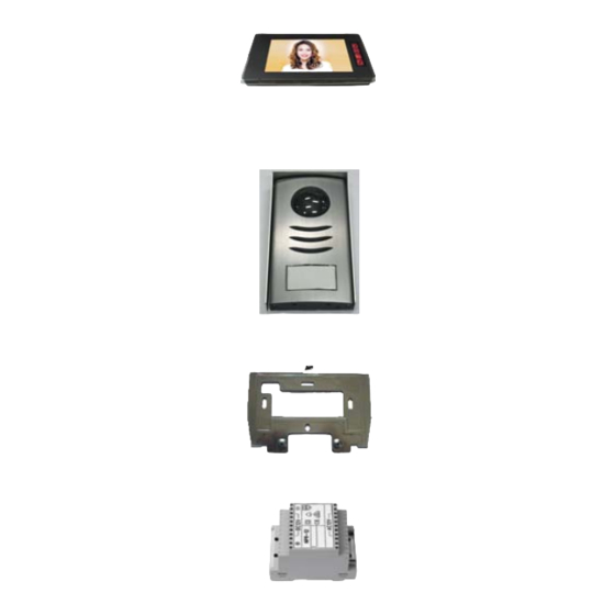
Parts Supplied
Ref
Description
Indoor
A
Monitor
Outdoor
B
Camera
Wall
D
mounting
bracket
Power
E
Transformer
Before You Start
• Check the pack and make sure you have all of the part listed above. If not,
contact your local store who will be able to help you.
Safety & Operating Instructions
VIDEO DOOR PHONE
NVM-704/NVC-3104
Illustration
Qty
1
1
1
1
Fittings Supplied
Ref
Description
Screw
H
(Dia 4x20mm)
Screw
I
(Dia 3x10mm)
J
Power cover
K
Locker
Bracket
L
Holder
Illustration
Qty
10
2
1
2
1
Page 1
Advertisement

Related Manuals for FUTURO NVM-704

Summary of Contents for FUTURO NVM-704
- Page 1 Safety & Operating Instructions FUTURO VIDEO DOOR PHONE NVM-704/NVC-3104 These instructions are for your safety. Please read through them thoroughly before use and retain for future reference. Parts Supplied Fittings Supplied Description Illustration Description Illustration Screw Indoor (Dia 4x20mm) Monitor...
- Page 2 Technical Characteristics Specifications Indoor Unit(NVM-704) Dimensions 235[W] ×120 [H] ×28 [D] mm Weight 0.7Kg Input Power DC14V (External Power Supply) Power Consumption Idle mode : 2W Operating : MAX 14W Connecting System 2 wires Voice transmission Full duplex two way communication...
- Page 3 Indoor unit 1. Monitor screen 2. Monitor on, off / Talk button 3. Door open button 4. No function 5. Intercom button 6. Volume control 7. Brightness control Outdoor unit Safety Instructions 1. Do not install near other electronic equipment such as computers, TV, video recorder as this may cause radiated interference to the unit.
-
Page 4: Wiring Diagram
10. This apparatus is designed for moderate climates. Do not use in high humidity, dusty or dirty areas. 11. To disconnect or isolate the unit, switch off at the socket or remove plug from wall socket. Please ensure the plug and socket is easily accessible. Warnings 1. - Page 5 A) Cable connection 1. Connect the monitor to the camera with the cable according to the wiring diagram below. 2. Carefully insert the wires to the terminal by pressing down the terminal flap with any small tool taking care that the 2 bare wires do not touch. B) Installation height 1.
- Page 6 2) If install additional monitor ,the first master monitor positioning the video ∞ switch of position and the last slave monitor positioning the video 3) switch at “ 75 Ω “ position. D) Installation of outdoor camera Add the name to the nameplate 1) Release the button block from the panel and remove the cover (Fig.
- Page 7 1) Remove the front cover (Fig. E & F) 2) Mount the outdoor unit on the wall by using 2 mounting screws and wall plugs. (Adjust the camera angle if necessary.)(Fig. G) 3) Replace the front cover and security it by replacing the 2 screws at the bottom of the camera.
- Page 8 An intercom calling can be started by any indoor monitor. When the intercom button on one indoor monitor is pressed,this will ring all monitors in a system,you can talk with the one calling monitor by pressing the intercom button on the second monitor. 5.
Need help?
Do you have a question about the NVM-704 and is the answer not in the manual?
Questions and answers