
Related Manuals for Cybertec Series 2000

Summary of Contents for Cybertec Series 2000
-
Page 1: User Manual
Series 2000 3G Modem / Router User Manual Document Number: 0013-001-000198 Version: 1.40 (15 October, 2010) - Page 2 fitness for a particular purpose, are made in relation to the accuracy and reliability or contents of this document. Cybertec Pty Ltd reserves the right to revise this document or withdraw it at any time without prior notice.
-
Page 3: Table Of Contents
6.3 Connecting to the Series 2000 Web Server ....... . . - Page 4 Document: 0013-001-000198 Version: 1.40 Copyright c 2010 Series 2000 User Manual 15 October, 2010 9 Status 9.1 Alarms ........... . .
- Page 5 18.1 Series 2000 does not start........
-
Page 6: Introduction
The communications interfaces include Ethernet and Serial, in addition some models include digital inputs and digital outputs. The Series 2000 3G Modem / Router range are designed to operate over a wide range of input voltage and an industrial temperature range. -
Page 7: Manual Updates
1.4 Default Configuration Unless otherwise stated the manual assumes the configuration of the Series 2000 3G Modem / Router is in the factory default state. If the modem has been previously configured it may be necessary to perform a configuration reset to return the the configuration to the default state, prior to configuring the device. -
Page 8: Indicators And Interfaces
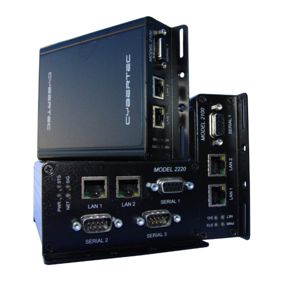
4 Indicators and Interfaces This section describes the indicators and interfaces for each of the models in the Series 2000 range. The Series 2000, Model 2100 and Model 2220 differ in that the the Model 2220 has 2 additional serial ports, digital inputs and digital outputs. -
Page 9: Indicators
15 October, 2010 Figure 4: Model 2220 rear panel. 4.3 Indicators The Series 2000 has 4 LED indicators on the front panel of the unit, refer to Figure 5 for the locations. Figure 5: Front panel indicators 4.3.1 Power Indicator The power indicator will light green when power is applied. -
Page 10: Ethernet
Document: 0013-001-000198 Version: 1.40 Copyright c 2010 Series 2000 User Manual 15 October, 2010 indicator will first light red, then flash red in sequence with the Signal Strength Indicator (refer to section 4.3.4), this is normal behaviour during boot-up and does not indicate a fault. -
Page 11: Modem / Dce Serial Port
4.5 Modem / DCE Serial Port The Series 2000 has one Data Communications Equipment (DCE) serial port. The Modem / DCE Serial port is an RS232 level serial port, accessed via the front panel DB9 female connector. Refer to Figure 7 and Table 4 for the connections to this port. -
Page 12: Digital Inputs & Digital Outputs (Model 2220 Only)
Document: 0013-001-000198 Version: 1.40 Copyright c 2010 Series 2000 User Manual 15 October, 2010 4.7 Digital Inputs & Digital Outputs (Model 2220 Only) The digital inputs and digital outputs are close contact type, the connectors are on the rear of the unit. The digital input connector is on the left hand side marked “IN”, the plug should be wired with reference to the circuit diagram shown in... -
Page 13: Factory Default Reset Switch
4.8 Factory Default Reset Switch The factory default reset switch is used to restore the configuration of the Series 2000 to the factory defaults. The switch is accessed through a small hole on the rear of the unit adjacent to the power connector, refer to Figure 11. To reset the configuration first power down the unit then using a suitable tool depress the factory default reset switch, restore power... -
Page 14: Installation
The Series 2000 may be DIN rail mounted, using the DIN rail mounting kit supplied. The DIN rail clips should be screwed to the mounting flanges as shown in figure 13. The DIN rail clips can then be used to attach the Series 2000 to a DIN rail. -
Page 15: Installing The Sim Card
The SIM card drawer eject button is a small yellow button located next to the SIM drawer on the rear panel of the Series 2000 . Refer to the image on the left of Figure 14 for the location of the SIM card eject button. To eject the SIM card drawer press the SIM card drawer eject button using a suitable tool and remove the drawer. -
Page 16: Power Supply
5.5 Power Supply The Series 2000 requires a DC power source in the voltage range of +10VDC to +60VDC. The power connector accepts a screw terminal plug which should be wired as shown in figure 16 and plugged into the power connector on the rear of the unit. -
Page 17: Accessing The Web Interface
6.1 Computer Settings In order to view the web pages a computer with a fixed IP address, on the same sub-net as the Series 2000 3G Modem / Router, will need to be connected to one of the LAN ports. - Page 18 Cybertec Pty Limited Document: 0013-001-000198 Version: 1.40 Copyright c 2010 Series 2000 User Manual 15 October, 2010 1. Open the Control Panel by selecting Start Control Panel. 2. Double click the Network Connections icon. 3. Double click the Network icon.
-
Page 19: Connecting To The Series 2000 Web Server
6.3 Connecting to the Series 2000 Web Server Open a web browser on the PC and browse to 10.10.10.10 (the default Series 2000, IP address) . A login box similar to Figure 20 will pop up. If the box fails to display, re-check the cable connections to the unit and the IP address settings of the PC. - Page 20 Cybertec Pty Limited Document: 0013-001-000198 Version: 1.40 Copyright c 2010 Series 2000 User Manual 15 October, 2010 Figure 21: Series 2000 Status summary Page 19 of 186...
-
Page 21: Web
To illustrate the page layout the Status web page is shown in figure 22, this is first page to be displayed when a connection to the web server is established. At the top of the page, under the Cybertec logo is the menu which consists of two rows of tabs. - Page 22 Series 2000 User Manual 15 October, 2010 7.2.1 Status The Status tab is used to report the current operating status of the Series 2000 3G Modem / Router . Figure 23: Status menu Alarms A summary of the alarm status.
- Page 23 Diagnostics Verify network connectivity with Ping and Traceroute. 7.2.5 Routing The Series 2000 3G Modem / Router supports static and dynamic routing as well as policy and Quality of Service (QoS) based routing. Routing options are accessed via the Routing tab.
- Page 24 Series 2000 User Manual 15 October, 2010 7.2.6 Firewall The Firewall tab allows configuration of the Series 2000 3G Modem / Router firewall settings which include the definition of port forwards and packet filters. Figure 28: Firewall menu Setup Enable NAPT, stateful packet inspection and connection tracking options.
-
Page 25: Symbols
Series 2000 User Manual 15 October, 2010 7.2.9 Management The Management tab provides access to the management settings of the Series 2000 3G Modem / Router . Figure 31: Serial Server menu Events Configure the actions taken when an event occurs. -
Page 26: Basic Configuration
8 Basic Configuration The section explains the procedure to configure the Series 2000 3G Modem / Router for basic packet mode functionality. For details on configuring the modem for Circuit Switched mode and for more advanced configuration refer to the Series 2000 3G Modem / Router User Manual. - Page 27 Cybertec Pty Limited Document: 0013-001-000198 Version: 1.40 Copyright c 2010 Series 2000 User Manual 15 October, 2010 Figure 33: SIM PIN control dialog. 8.1.3 Adding a Network Connection Profile To access the wireless packet mode settings click on the “Packet mode” tab. The screen shown in Figure 34 will be displayed.
- Page 28 To complete the configuration of the wireless connection, set the Connection state to “Always connect” and click the “Update” button to save the changes. Once the changes have been set, the Series 2000 3G Modem / Router will attempt to establish a connection to a wireless network. The connection time will vary and may take several minutes to complete.
- Page 29 Cybertec Pty Limited Document: 0013-001-000198 Version: 1.40 Copyright c 2010 Series 2000 User Manual 15 October, 2010 8.1.5 Connection Status To check the status of the connection select “Status” from the top level menu and then select “Wireless” from the second level menu.
-
Page 30: Configure The Lan Interface And Dhcp Server
Enter the new IP address and netmask in the Interface Configuration table. Click Update to set the changes. Once the changes have been set, the IP address of the Series 2000 3G Modem / Router will change. Enter the new address in the browser on the PC. It will be necessary to login again, following the procedure described in the previous section. -
Page 31: Configure Clients To Use The Series 2000 3G Modem / Router
If the clients have a DHCP address allocated by the Series 2000 3G Modem / Router, they will have learned the necessary settings. No further configuration is needed. If clients have static IP addresses, set their default route and DNS server to the IP address of the Series 2000 3G Modem / Router . -
Page 32: Status
9 Status The Status pages provides access to status reporting for various service of the Series 2000 3G Modem / Router . If the device is not working correctly these pages will help diagnose the problem. Regular checking and refreshing of these pages is recommended to ensure all services are operating correctly. - Page 33 Document: 0013-001-000198 Version: 1.40 Copyright c 2010 Series 2000 User Manual 15 October, 2010 Figure 42: Alarms status page showing Wireless connection status fault. The page is divided into sections representing the status of system level services, the Wireless and LAN interfaces and other services.
-
Page 34: Wireless
Cybertec Pty Limited Document: 0013-001-000198 Version: 1.40 Copyright c 2010 Series 2000 User Manual 15 October, 2010 9.2 Wireless The Wireless status page (Status Wireless) provides details of the current operating state of the wireless interface. The page displayed will depend on the wireless operating mode, Figure 43 shows the page for packet mode, while Figure 44 for Circuit Switched Data (CSD) mode. - Page 35 Cybertec Pty Limited Document: 0013-001-000198 Version: 1.40 Copyright c 2010 Series 2000 User Manual 15 October, 2010 Figure 44: Wireless status page for Circuit Switched Data (CSD) mode. 9.2.3 Connection Status (Packet Mode) Line State The current status of the connection either offline or connected.
-
Page 36: Local Area Network (Lan)
Cybertec Pty Limited Document: 0013-001-000198 Version: 1.40 Copyright c 2010 Series 2000 User Manual 15 October, 2010 9.3 Local Area Network (LAN) The Local Area Network (LAN) status page (Status LAN) provides details of the current operating state of the LAN or Ethernet interface. - Page 37 Cybertec Pty Limited Document: 0013-001-000198 Version: 1.40 Copyright c 2010 Series 2000 User Manual 15 October, 2010 Figure 47: System Log page. Page 36 of 186...
-
Page 38: System
10 System The System section provides configuration options and access to features to allow the administration and maintenance of the Cybertec Series 2000 3G Modem / Router . Options which can be configured include: Host-name for the device. Time and Date settings. - Page 39 Document: 0013-001-000198 Version: 1.40 Copyright c 2010 Series 2000 User Manual 15 October, 2010 10.1.1 Setting the system hostname The hostname for the modem can be set in the Hostname field. The hostname is limited to 32 characters and can only contain letters, numbers, hyphens and underscores.
- Page 40 10.1.4 Setting a timed reboot In some applications, it may be desirable for the Series 2000 3G Modem / Router reboot at a timed interval to catch any errors that may have occurred. To enable this feature, enter a time (in hours) in the Timed reboot field. Once the modem has run for the number of hours entered, it will reboot and start the system again.
-
Page 41: Backup & Upgrade
10.2.1 Backing up the current configuration The configuration of the Series 2000 can be saved as a file to a PC. This file can then be used to restore the configuration of the unit at some later time or used to configure multiple units with the same configuration. - Page 42 The Series 2000 firmware can be upgraded via the web interface. To upgrade the Series 2000 firmware, click the Browse button in the section titled Upgrade Series 2000 firmware then navigate to and select the upgrade file. Once selected, the filename will display as shown highlighted in Figure 54.
- Page 43 Figure 54: Select firmware upgrade file To initiate the upload of the file to the Series 2000 click the Upload button. The file will now be uploaded to the Series 2000 . The upload may take from several seconds to several minutes depending on the speed of the link the upgrade file is transferred over.
-
Page 44: System Information
10.4 Power The power controller may be used to power the Series 2000 3G Modem / Router on and off at specified times. By using the power controller the power consumption can be greatly reduced at times when a network connection is not required. - Page 45 Document: 0013-001-000198 Version: 1.40 Copyright c 2010 Series 2000 User Manual 15 October, 2010 Figure 58: The Power Control Schedule configuration page. For the power controller to work correctly power must be maintained to the unit at all times. During the power off times the power consumption will drop to approximately 10mA.
-
Page 46: General Purpose Inputs And Outputs (Gpio) (Model 2220Only)
10.5 General Purpose Inputs and Outputs (GPIO) (Model 2220only) The General Purpose Inputs and Outputs (GPIO) provide the Series 2000 3G Modem / Router with a way in which to monitor and control external devices. The inputs may be used to trigger events such as ending an SMS or SNMP trap. - Page 47 Cybertec Pty Limited Document: 0013-001-000198 Version: 1.40 Copyright c 2010 Series 2000 User Manual 15 October, 2010 Figure 61: The GPIO configuration page. 10.5.1 GPIO Configuration The GPIO Configuration of the page is used to configure the individual inputs and outputs. The options are: Type This field describes the I/O type and is one of:...
- Page 48 Cybertec Pty Limited Document: 0013-001-000198 Version: 1.40 Copyright c 2010 Series 2000 User Manual 15 October, 2010 10.5.2 General Configuration The general configuration is used to configure the way in which the unit will respond to SMS. The options are: SMS contents on event Should an input or output cause an SMS event to be generated, the value set in this field deter-...
- Page 49 Cybertec Pty Limited Document: 0013-001-000198 Version: 1.40 Copyright c 2010 Series 2000 User Manual 15 October, 2010 Figure 63: The GPIO SMS event configuration example. If the alarms inputs are now closed the following SMSes will be sent: First the Input-1 the Door alarm is closed:...
-
Page 50: Wireless
15 October, 2010 11 Wireless This section describes the 3G Wireless interface options of the Series 2000 3G Modem / Router . The Series 2000 supports two modes of operation: packet mode and Circuit Switched Data (CSD) mode. The subsections of the configuration are: Network - Configure the operation mode, select the frequency band of operation and set the SIM PIN. - Page 51 Document: 0013-001-000198 Version: 1.40 Copyright c 2010 Series 2000 User Manual 15 October, 2010 Circuit switched mode Circuit Switched Data mode is similar to a traditional dial-up modem. It is mainly intended for the transport of serial data. Connections are established by dialing into the modem using a PSTN modem or dialing out a call via AT commands on the serial port.
- Page 52 The Series 2000 is capable of operating on several frequency bands used by the UMTS (3G) and GSM protocols. The default setting is for the Series 2000 to operate on all supported frequency bands. This means that when powered on the Series 2000 will start to search for available networks, checking first for UMTS (3G) networks then falling back to...
-
Page 53: Packet Mode Configuration
Document: 0013-001-000198 Version: 1.40 Copyright c 2010 Series 2000 User Manual 15 October, 2010 Custom The user can set checkboxes in the UMTS and GSM rows to select the frequency bands that will be searched. Figure 71: Frequency Band Selection - Custom Once any changes have been made to the frequency bands click the Update button the commit the changes. - Page 54 Cybertec Pty Limited Document: 0013-001-000198 Version: 1.40 Copyright c 2010 Series 2000 User Manual 15 October, 2010 The network provider will specify the required settings for completing a connection profile. The settings required are listed below: APN (Access Point Name) This is the name of the network provider’s access point.
- Page 55 Cybertec Pty Limited Document: 0013-001-000198 Version: 1.40 Copyright c 2010 Series 2000 User Manual 15 October, 2010 Click Update to set the change to the connection state. Once the state has been set, the modem will attempt to establish a connection.
- Page 56 Document: 0013-001-000198 Version: 1.40 Copyright c 2010 Series 2000 User Manual 15 October, 2010 To change the selected profile select the required index number from the Current profile drop down box in the Connection Configuration section and click Update. The page will update and the selected index will now be highlighted. Figure 78 is an example with the second profile added above selected.
- Page 57 Cybertec Pty Limited Document: 0013-001-000198 Version: 1.40 Copyright c 2010 Series 2000 User Manual 15 October, 2010 11.2.5 Deleting a profile A profile can be deleted by clicking the icon located in the Delete column for the profile to be deleted. Click OK to confirm the deletion.
- Page 58 Cybertec Pty Limited Document: 0013-001-000198 Version: 1.40 Copyright c 2010 Series 2000 User Manual 15 October, 2010 Figure 83: Wireless Status page The section tiled Network Status details the quality of the service available from the 3G network. The SIM Card field will only be shown if an error with the SIM card has been detected, and will be reported as Absent or faulty or PIN needed as shown highlighted in Figures 84 and 85.
-
Page 59: Connection Management
Poor signal strength. Check the antenna is properly connected and experiment with different locations for the Series 2000 to achieve a higher RF Level. Problem with the SIM card. Ensure the SIM card fitted to the Series 2000 is currently enabled with the network provider. - Page 60 Document: 0013-001-000198 Version: 1.40 Copyright c 2010 Series 2000 User Manual 15 October, 2010 To access the connection management options, select Wireless from the main menu and Connection Management from the sub-menu. The connection management page as shown in figure 86 will be displayed.
- Page 61 11.3.2 Connection Maintenance The connection maintenance refers to the tests employed by the Series 2000 to determine that a valid network connection is available. Should the connection maintenance test fail then the Series 2000 will attempt to re-establish the connection.
-
Page 62: Circuit Switched Data Mode
Automatically obtain DNS If set to Yes the DNS server addresses received when a connection is established will be used by the Series 2000 to direct DNS requests. If this value is set to No a DNS server should be entered manually. - Page 63 Cybertec Pty Limited Document: 0013-001-000198 Version: 1.40 Copyright c 2010 Series 2000 User Manual 15 October, 2010 Figure 87: Circuit switched configuration The number of Ports listed is model dependent. The Model 2220 has 1 serial port so only while serial port will be listed while Model 2220 has 3 serial ports so 3 will be listed.
- Page 64 Cybertec Pty Limited Document: 0013-001-000198 Version: 1.40 Copyright c 2010 Series 2000 User Manual 15 October, 2010 None No flow control is enabled. Hardware The port will use the RTS and CTS handshake lines to control the flow of data.
- Page 65 Document: 0013-001-000198 Version: 1.40 Copyright c 2010 Series 2000 User Manual 15 October, 2010 11.4.3 Configuring for multiplexed mode Multiplexed mode allows a remote user to dial in to the modem and select the port they wish to communicate with.
- Page 66 Cybertec Pty Limited Document: 0013-001-000198 Version: 1.40 Copyright c 2010 Series 2000 User Manual 15 October, 2010 Figure 91: Configuring multiplexed mode The following options can be configured for multiplexed mode: Menu visibility Depending on the application, it may not be desirable to have the multiplexer present menu prompts to the remote modem.
- Page 67 Cybertec Pty Limited Document: 0013-001-000198 Version: 1.40 Copyright c 2010 Series 2000 User Manual 15 October, 2010 Figure 92: PPP server configuration To configure PPP server mode, click the icon in the upper table. The PPP server configuration page, as shown in Figure 93 will be displayed.
- Page 68 Cybertec Pty Limited Document: 0013-001-000198 Version: 1.40 Copyright c 2010 Series 2000 User Manual 15 October, 2010 Figure 94: PPP dialout configuration. To configure PPP server mode, click the icon in the upper table. The PPP dialout configuration page, as shown in Figure 95 will be displayed.
-
Page 69: Sms
11.5 SMS The Series 2000 provides SMS triggers which can be used to change the Wireless operating mode, reboot the modem and request a status summary. Each SMS trigger can individually be enabled and disabled and the text trigger can be defined for each trigger. - Page 70 Cybertec Pty Limited Document: 0013-001-000198 Version: 1.40 Copyright c 2010 Series 2000 User Manual 15 October, 2010 Figure 96: SMS Triggers configuration page for the Model 2100. Figure 97: SMS Triggers configuration page for the Model 2220. 11.5.1 Trigger configuration The fields below, found in the SMS Triggers table, configure an individual trigger:...
- Page 71 Cybertec Pty Limited Document: 0013-001-000198 Version: 1.40 Copyright c 2010 Series 2000 User Manual 15 October, 2010 System Status query Query the current state. An SMS will be returned providing current status information. Reboot Initiate a reboot. Wireless Packet mode Switch to packet mode.
- Page 72 Cybertec Pty Limited Document: 0013-001-000198 Version: 1.40 Copyright c 2010 Series 2000 User Manual 15 October, 2010 11.5.2.1 Setting the default policy to allow This example describes setting the default policy to Allow then adding an entry to blacklist a particular number.
- Page 73 Cybertec Pty Limited Document: 0013-001-000198 Version: 1.40 Copyright c 2010 Series 2000 User Manual 15 October, 2010 11.5.2.2 Deleting an Entry To delete an entry click the the icon a dialog box similar to that shown in Figure x will be displayed. Click the OK button to remove the entry.
- Page 74 Document: 0013-001-000198 Version: 1.40 Copyright c 2010 Series 2000 User Manual 15 October, 2010 Figure 102: SMS access control default policy set to Drop. 1. In the section titled SMS Access Control set the Action for the Default policy to Drop.
- Page 75 Cybertec Pty Limited Document: 0013-001-000198 Version: 1.40 Copyright c 2010 Series 2000 User Manual 15 October, 2010 Figure 104: SMS Triggers number to accept added 11.5.2.4 Editing an Entry To edit an entry click the icon. Click the Update button once changes have been completed to save the changes.
- Page 76 Cybertec Pty Limited Document: 0013-001-000198 Version: 1.40 Copyright c 2010 Series 2000 User Manual 15 October, 2010 Figure 105: SMS Example configuration. 11.5.3.1 Status Query The status query SMS is issued as follows: Query status The modem responds with: Host:S2000-ff-ff-00, Uptime:14003399, Temp:37.25, RSSI:20, Mode:Pkt,...
- Page 77 11.5.3.3 Wireless Mode In this example the Series 2000 3G Modem / Router will be switched from packet mode to circuit switched data mode and back to packet mode. From the Status query example above the unit is currently in packet mode so the first SMS will be to switch to CSD mode.
- Page 78 Cybertec Pty Limited Document: 0013-001-000198 Version: 1.40 Copyright c 2010 Series 2000 User Manual 15 October, 2010 11.5.3.4 VPN Control The VPN control SMS is issued as follows: VPN restart ALL This SMS command will restart all enabled VPNs. To restart only the VPN labeled test the following SMS command would be issued: VPN restart test 11.5.3.5 GPIO (Model 2220only)
- Page 79 Cybertec Pty Limited Document: 0013-001-000198 Version: 1.40 Copyright c 2010 Series 2000 User Manual 15 October, 2010 The response will be similar to: S2000-ff-ff-00:Input-1=open, Input-2=open, Output-1=closed, Output-2=closed The state of the two outputs has changed from “open” to “closed”. Page 78 of 186...
-
Page 80: Network
12.1 LAN Interface The LAN Interface refers to the two switched Ethernet ports located on the front of the Series 2000 3G Modem / Router . To access the LAN Interface settings select Network LAN. Figure 106 is an example of the LAN settings page. - Page 81 To re-enable the LAN ports without accessing the web interface, it will be necessary to perform a factory reset of the Series 2000 3G Modem / Router modem as described in Section 4.8 on page 12. This will clear all the configuration settings of the Series 2000 3G Modem / Router to the factory default settings and the LAN ports will be enabled.
-
Page 82: Configuring The Dhcp Server
The DHCP server allows clients on the local network to be automatically allocated IP addresses from the modem. The Series 2000 3G Modem / Router will also provide the clients with network settings like their default route and DNS servers. - Page 83 This simplifies configuration of LAN clients, as they only need configure the modem as their DNS server. If the DHCP server of the Series 2000 3G Modem / Router has been enabled then any device that is connected to the LAN interface and has an IP address from the DHCP server will automatically be given the IP address of the modem as their DNS server.
- Page 84 Note: Some wireless providers do not allow inbound connections at all, so even though the dynamic DNS client will connect and register the IP address provided to the Series 2000 3G Modem / Router unit, all attempts to connect to that IP address will fail.
-
Page 85: Generic Routing Encapsulation (Gre)
Cybertec Pty Limited Document: 0013-001-000198 Version: 1.40 Copyright c 2010 Series 2000 User Manual 15 October, 2010 12.4 Generic Routing Encapsulation (GRE) Generic Routing Encapsulation (GRE) is a tunneling protocol which can encapsulate a wide variety of network layer protocol packet types inside IP tunnels. To access the GRE configuration page select Network GRE a page similar to that shown in Figure 111 will be displayed. -
Page 86: Network Diagnostics
Cybertec Pty Limited Document: 0013-001-000198 Version: 1.40 Copyright c 2010 Series 2000 User Manual 15 October, 2010 12.5 Network Diagnostics Ping and Traceroute are two commonly used tools for analysing packet flows and diagnosing network issues. The Series 2000 3G Modem / Router can generate ping and traceoute requests via the web interface. To access the diagnostic tools, select Network Diagnostics. -
Page 87: Routing
15 October, 2010 13 Routing The Series 2000 3G Modem / Router has multiple networking interfaces, including the wireless interface, the LAN interface and the VPN tunnels. The routing configuration of the modem determines how packets arriving from the different interfaces will be delivered to their destination. - Page 88 Series 2000 User Manual 15 October, 2010 WLS CSD The wireless circuit switched data interface. This option is only valid if the Series 2000 3G Modem / Router is operating in Circuit Switched Data (CSD) mode and the PPP server has been enabled.
- Page 89 Virtual Private Network (VPN) for details. WLS CSD The wireless circuit switched data interface. This option is only valid if the Series 2000 3G Modem / Router is operating in Circuit Switched Data (CSD) mode and the PPP server has been enabled.
- Page 90 Document: 0013-001-000198 Version: 1.40 Copyright c 2010 Series 2000 User Manual 15 October, 2010 Figure 120: Adding a new static route To add the route click the Update button. The main page will again be shown with the new route added, as seen in Figure 121.
- Page 91 Cybertec Pty Limited Document: 0013-001-000198 Version: 1.40 Copyright c 2010 Series 2000 User Manual 15 October, 2010 Figure 123: The main route table after editing route two 13.1.6 Deleting a static route icon in the Delete column of the route to be deleted. A warning box will A static route can be deleted by clicking the be displayed.
-
Page 92: Dynamic Routing
13.2 Dynamic Routing 13.2.1 Description The Series 2000 3G Modem / Router modem supports the Routing Information Protocol (RIP) for exchanging routing information with neighbouring routers. RIP is a dynamic routing protocol used in local and wide area networks and is supported in many routers. - Page 93 Cybertec Pty Limited Document: 0013-001-000198 Version: 1.40 Copyright c 2010 Series 2000 User Manual 15 October, 2010 Figure 127: VRRP network scenario To access the VRRP configuration, select Routing VRRP a page similar to that shown in Figure128 will be displayed.
- Page 94 Document: 0013-001-000198 Version: 1.40 Copyright c 2010 Series 2000 User Manual 15 October, 2010 Once enabled, VRRP will change the MAC address of the LAN interface. This may make the internal web server temporarily unavailable until the change in address has propagated.
-
Page 95: Policy Routing
Cybertec Pty Limited Document: 0013-001-000198 Version: 1.40 Copyright c 2010 Series 2000 User Manual 15 October, 2010 13.4 Policy Routing 13.4.1 Description Policy routing is an advanced routing feature that allows packets to be routed based on which of the modem’s network interfaces they arrive on, the protocol type or the source or destination address. - Page 96 Virtual Private Network (VPN) for details. WLS CSD The wireless circuit switched data interface. This option is only valid if the Series 2000 3G Modem / Router is operating in Circuit Switched Data (CSD) mode and the PPP server has been enabled.
- Page 97 Document: 0013-001-000198 Version: 1.40 Copyright c 2010 Series 2000 User Manual 15 October, 2010 To save the new route click the Update button. The main Policy Route page will again be shown with the new route listed, as shown in Figure 134.
- Page 98 Document: 0013-001-000198 Version: 1.40 Copyright c 2010 Series 2000 User Manual 15 October, 2010 Figure 137: Editing a policy route To save the changes click the Update button or to lose any changes click the Cancel button. The main page will again be displayed as shown in Figure 138, with the changes for route 2 added to the table.
-
Page 99: Quality Of Service Routing
Cybertec Pty Limited Document: 0013-001-000198 Version: 1.40 Copyright c 2010 Series 2000 User Manual 15 October, 2010 Figure 140: Policy route table with route two removed 13.5 Quality of Service Routing 13.5.1 Description For bandwidth intensive applications, such as live video or Voice-over-IP (VOIP), it may be desirable to have certain types of traffic prioritised for transmission out the Wireless interface in preference to other traffic. - Page 100 Cybertec Pty Limited Document: 0013-001-000198 Version: 1.40 Copyright c 2010 Series 2000 User Manual 15 October, 2010 13.5.3 Basic QoS Configuration As an example of how to complete the basic QoS configuration, assume the maximum uplink bandwidth is 350kbits/sec. QoS would then be set with the following values: QoS enabled check to enable QoS Max uplink rate Set to 350.
- Page 101 Document: 0013-001-000198 Version: 1.40 Copyright c 2010 Series 2000 User Manual 15 October, 2010 Source address If selected, either a single address (for example, 172.16.1.132) or a subnet range (for example, 172.16.0.0/24) can be entered. Only packets matching this source address will have the route applied to them.
- Page 102 Document: 0013-001-000198 Version: 1.40 Copyright c 2010 Series 2000 User Manual 15 October, 2010 Again notice that in the centre column, Protocol, Destination address and Destination port or range are checked. This indicates these are the matching criteria that will be applied to packets. All criteria that are unchecked will be ignored.
- Page 103 Document: 0013-001-000198 Version: 1.40 Copyright c 2010 Series 2000 User Manual 15 October, 2010 Figure 148: Editing a QoS route To save the changes click the Update button or to lose any changes click the Cancel button. The main page will again be displayed as shown in Figure 149, with the changes for route 2 added to the table.
- Page 104 Cybertec Pty Limited Document: 0013-001-000198 Version: 1.40 Copyright c 2010 Series 2000 User Manual 15 October, 2010 The route table will be displayed with the route removed, as shown in Figure 151. Figure 151: QoS route table with route two removed...
-
Page 105: Firewall
14.1 Firewall Setup The Series 2000 3G Modem / Router firewall configuration is accessed by selecting the Firewall tab from the main menu. When selected the page shown in Figure 152 will be displayed. This page shows and allows configuration of the basic settings for the firewall. -
Page 106: Access Control
Cybertec Pty Limited Document: 0013-001-000198 Version: 1.40 Copyright c 2010 Series 2000 User Manual 15 October, 2010 14.1.2 Stateful Packet Inspection (SPI) The firewall in the modem can function in Stateful Packet Inspection (SPI) mode. When enabled, the firewall will track the state of each connection passing through it (for example, TCP streams) and only allow packets belonging to a known connection to enter from the wireless port. -
Page 107: Dos Filters
Cybertec Pty Limited Document: 0013-001-000198 Version: 1.40 Copyright c 2010 Series 2000 User Manual 15 October, 2010 Figure 153: Firewall access control options 14.2.2 Accessing modem services from the wireless port or VPN tunnels The External Access table on the Access Control page is shown in Figure 153. It controls which services can be accessed from the wireless port and VPN tunnels. -
Page 108: Custom Filters
Document: 0013-001-000198 Version: 1.40 Copyright c 2010 Series 2000 User Manual 15 October, 2010 14.3.2 Enabling the Denial of Service filters The Filter Description table provides a number of DOS filters, as shown in Figure 154. The filters can be applied to packets received from the LAN port, the wireless port (WLS), and from any VPN tunnel by checking the boxes in the appropriate column. - Page 109 Document: 0013-001-000198 Version: 1.40 Copyright c 2010 Series 2000 User Manual 15 October, 2010 14.4.2 Custom filter options The custom filter options are shown when the Add new custom filter button is clicked or an existing route is edited. The custom filter options are shown in Figure 156.
- Page 110 Document: 0013-001-000198 Version: 1.40 Copyright c 2010 Series 2000 User Manual 15 October, 2010 14.4.3 Adding a new custom filter From the main Custom Filters page click the Add new custom filter button. This will select the Add new custom filter page.
- Page 111 Document: 0013-001-000198 Version: 1.40 Copyright c 2010 Series 2000 User Manual 15 October, 2010 Figure 159: Adding a new custom filter To add the filter to the filters table click the Update button, the main page will again be shown with the new filter added, as seen in Figure 160.
- Page 112 Document: 0013-001-000198 Version: 1.40 Copyright c 2010 Series 2000 User Manual 15 October, 2010 Figure 161: Editing a custom filter To save the changes click the Update button or to lose any changes click the Cancel button. The main page will again be displayed as shown in Figure 162, with the changes for filter 2 added to the table.
-
Page 113: Port Forwarding
Cybertec Pty Limited Document: 0013-001-000198 Version: 1.40 Copyright c 2010 Series 2000 User Manual 15 October, 2010 The filter table will be displayed with filter removed, as shown in Figure 164. Figure 164: Custom filter table with filter 2 removed 14.5 Port Forwarding... - Page 114 Document: 0013-001-000198 Version: 1.40 Copyright c 2010 Series 2000 User Manual 15 October, 2010 Protocol The modem is able to forward TCP, UDP, GRE, ESP and AH. Most forwards will be either TCP or UDP. Select the appropriate protocol from the list.
- Page 115 Document: 0013-001-000198 Version: 1.40 Copyright c 2010 Series 2000 User Manual 15 October, 2010 Figure 169: Adding a second port forward To add the new port forward to the port forward table click the Update button. The main page will again be shown with the new port forward added, as seen in Figure 170.
-
Page 116: Custom Nat
Cybertec Pty Limited Document: 0013-001-000198 Version: 1.40 Copyright c 2010 Series 2000 User Manual 15 October, 2010 Figure 172: Main port forward page with revised port forward 14.5.5 Deleting a port forward A port forward can be deleted by clicking the icon in the Delete column of the forward to be deleted. - Page 117 Cybertec Pty Limited Document: 0013-001-000198 Version: 1.40 Copyright c 2010 Series 2000 User Manual 15 October, 2010 Source-NAT on all packets being transmitted out a VPN tunnel. Destination-NAT to redirect packets to a host on the LAN. To access the Custom NAT configuration page, select Firewall Custom NAT, a page similar to that shown in Figure 175 will be displayed.
- Page 118 Document: 0013-001-000198 Version: 1.40 Copyright c 2010 Series 2000 User Manual 15 October, 2010 Outgoing interface If selected, packets will be matched based on the network interface they will be transmitted on. Note that this can only be applied to a Source NAT.
- Page 119 Document: 0013-001-000198 Version: 1.40 Copyright c 2010 Series 2000 User Manual 15 October, 2010 Figure 178: Main custom NAT page showing new custom NAT added to the table To add a second custom NAT again click the Add new custom NAT button. In the example shown in Figure 179, a destination NAT is created for packets destined for the wireless port.
- Page 120 Document: 0013-001-000198 Version: 1.40 Copyright c 2010 Series 2000 User Manual 15 October, 2010 Figure 181: Editing a custom NAT To save the changes click the Update button or to lose the changes click Cancel. The main page will again be displayed as shown in Figure 182, with the changes for custom NAT 2 added to the table.
-
Page 121: Mac Address Filtering
A unique Media Access Control (MAC) address is assigned to every Ethernet device. This address can be filtered to either allow or deny a device access to a network. The Series 2000 3G Modem / Router supports MAC address filtering. - Page 122 Care should be taken when configuring MAC Filters to ensure the computer being used to configure the Series 2000 3G Modem / Router is not denied access if as likely it is connected to the LAN interface. When changing filters it is recommended to first add a specific filter to allow access to the computer being used for configuration.
- Page 123 Document: 0013-001-000198 Version: 1.40 Copyright c 2010 Series 2000 User Manual 15 October, 2010 Figure 187: Adding a custom NAT Click Update to save the new MAC filter. The MAC filter table will be updated to include the MAC filter rule as shown in Figure 188.
- Page 124 Cybertec Pty Limited Document: 0013-001-000198 Version: 1.40 Copyright c 2010 Series 2000 User Manual 15 October, 2010 14.7.5 Editing a MAC Filter icon in the Edit column of the filter to be changed. Once clicked, the A MAC Filter can be edited by clicking the details of the MAC Filter will be displayed in the same table as when creating a new MAC Filter.
- Page 125 Cybertec Pty Limited Document: 0013-001-000198 Version: 1.40 Copyright c 2010 Series 2000 User Manual 15 October, 2010 To delete MAC Filter 2 from the table shown in Figure 193, click the icon in row 2 of the table. A warning box will now be displayed as shown if Figure 194.
-
Page 126: Virtual Private Network (Vpn)
2000 3G Modem / Router the secured communications network is tunneled through the 3G wireless network and then over the Internet or private network to a VPN-capable router or server. The Series 2000 3G Modem / Router has support for IPsec, SSL and PPTP/L2TP based VPNs and can be configured for multiple VPN tunnels to operate simultaneously. - Page 127 UDP and IP headers. If the wireless interface of the Series 2000 3G Modem / Router is allocated a dynamic and private IP address then the connection to the Internet will be via a Network Address Translator (NAT). This will require the use of NAT-Traversal for IPsec to establish a connection.
- Page 128 Cybertec Pty Limited Document: 0013-001-000198 Version: 1.40 Copyright c 2010 Series 2000 User Manual 15 October, 2010 15.1.2.2 Physical Configuration The second page is the Physical Configuration page, the options on the page will depend on the functional mode selected, Figure 198 shows the options for the initiator mode while Figure 199 shows the options for the responder mode.
- Page 129 Cybertec Pty Limited Document: 0013-001-000198 Version: 1.40 Copyright c 2010 Series 2000 User Manual 15 October, 2010 Figure 200: IPsec Phase 1 configuration The options for Phase 1configuration are: Authentication method Select the authentication method from the drop-down list. The options are:...
- Page 130 Document: 0013-001-000198 Version: 1.40 Copyright c 2010 Series 2000 User Manual 15 October, 2010 IPv4 The local ID will be a standard IP address (eg 123.123.123.123). Enter the IP address in this field. FQDN Fully Qualified Domain Name. The local ID will present a hostname as its ID. Enter the name in this field.
- Page 131 Cybertec Pty Limited Document: 0013-001-000198 Version: 1.40 Copyright c 2010 Series 2000 User Manual 15 October, 2010 Figure 202: IPsec Phase 2 configuration with Xauth enabled. The phase 2 options are: Authentication method Select the extended authentication method, the options are: None No extended authentication.
- Page 132 Cybertec Pty Limited Document: 0013-001-000198 Version: 1.40 Copyright c 2010 Series 2000 User Manual 15 October, 2010 Perfect forward secrecy Check to enable perfect forward secrecy. Diffie-Hellman Group Select the Diffie-Hellman Group from the drop-down list, the options are: DH Grp 1 (768) The 768 bit Diffie-Hellman group.
- Page 133 Cybertec Pty Limited Document: 0013-001-000198 Version: 1.40 Copyright c 2010 Series 2000 User Manual 15 October, 2010 Clear Clear the route. Generally only used by responder. Restart Attempts to restart the tunnel. Generally set for initiator. Restart by peer Restart every tunnel associated with the peer.
- Page 134 The example assumes that the router has been configured, has a static IP address and is directly accessible from the Internet. The IPsec tunnel will be terminated as a virtual host on the Series 2000 3G Modem / Router with IP address 11.22.33.44 and will be terminated on a LAN subnet at the router with address 192.168.2.0/24...
- Page 135 Cybertec Pty Limited Document: 0013-001-000198 Version: 1.40 Copyright c 2010 Series 2000 User Manual 15 October, 2010 The tunnel will be named Test. It will operate in Tunnel mode and will act as the initiator. The configure settings required are:...
- Page 136 Cybertec Pty Limited Document: 0013-001-000198 Version: 1.40 Copyright c 2010 Series 2000 User Manual 15 October, 2010 Figure 208: IPsec phase 1 configuration example. The required parameters are as follows: Phase 1 Configuration section Authentication method: Pre-shared key Negotiation mode: Aggressive mode...
- Page 137 Cybertec Pty Limited Document: 0013-001-000198 Version: 1.40 Copyright c 2010 Series 2000 User Manual 15 October, 2010 Figure 209: IPsec phase 2 configuration example. Authentication method None Phase 2 Encryption section ESP proposal: Encryption Algorithm: AES (128) Authentication Algorithm: SHA1 Perfect forward secrecy &...
- Page 138 Cybertec Pty Limited Document: 0013-001-000198 Version: 1.40 Copyright c 2010 Series 2000 User Manual 15 October, 2010 Allow rekeying, margin (mins) & fuzz: Allow rekeying Checked to enable. Margin 10 Minutes. Fuzz 100%. Dead Peer Detection Enable Check to enable.
- Page 139 Cybertec Pty Limited Document: 0013-001-000198 Version: 1.40 Copyright c 2010 Series 2000 User Manual 15 October, 2010 Figure 212: IPsec table with the newly created entry. 15.1.3.6 Enable IPsec To complete the configuration in the General IPsec Configuration enable IPsec by checking the Enabled check-box and enable NAT traversal.
-
Page 140: Secure Sockets Layer (Ssl) Vpn
Cybertec Pty Limited Document: 0013-001-000198 Version: 1.40 Copyright c 2010 Series 2000 User Manual 15 October, 2010 Figure 214: IPsec connection status The status web pages do not automatically refresh so it may be necessary to refresh the page to obtain the current status. - Page 141 Document: 0013-001-000198 Version: 1.40 Copyright c 2010 Series 2000 User Manual 15 October, 2010 15.2.1 SSL VPN configuration To access the SSL VPN configuration page, select VPN SSL VPN a page similar to that shown in Figure 216 will be displayed.
- Page 142 Cybertec Pty Limited Document: 0013-001-000198 Version: 1.40 Copyright c 2010 Series 2000 User Manual 15 October, 2010 15.2.1.2 Advanced Configuration The advanced options provide more control of the VPN. For most applications the default options do not need to be changed.
- Page 143 This section describes an example of connecting to a VPN server. Figure 218 illustrates the network which will be estab- lished. For this example a connection will be established from the Series 2000 3G Modem / Router to an OpenVPN server using a routed connection and UDP as the connection protocol.
- Page 144 Cybertec Pty Limited Document: 0013-001-000198 Version: 1.40 Copyright c 2010 Series 2000 User Manual 15 October, 2010 Figure 219: SSL based VPN configuration web page The following are configuration settings used for the example: Basic Configuration options Enabled: Checked Connection Protocol: UDP Transport Type: Routed Remote address: 123.123.123.123...
-
Page 145: Pptp And L2Tp
7 packets transmitted, 7 received, 0% packet loss, time 5998ms rtt min/avg/max/mdev = 120.620/124.725/141.429/6.867 ms The Series 2000 3G Modem / Router has responded to the ping and the byte counters on the status page have increased as seen in Figure 221 Figure 221: SSL VPN status after running Ping, the byte counts have increased The VPN is now operational as can be used to pass data. - Page 146 L2TP Network Server (LNS), the LNS waits for new tunnels to be established. The other endpoint is called the L2TP Access Concentrator (LAC), the LAC initiates tunnel connections to the LNS, the Series 2000 3G Modem / Router implements an L2TP LAC.
- Page 147 The following is an example of connecting a PPTP tunnel to a PPTP VPN server. Figure 224 illustrates the network which will be established. For this example a connection will be established from the Series 2000 3G Modem / Router to a PPTP server.
- Page 148 The settings will be saved and the main PPTP & L2TP page will be displayed with the new tunnel added to the Tunnels table, as shown in Figure 226. The Series 2000 3G Modem / Router will now attempt to establish a connection with the PPTP server.
-
Page 149: Multiple Vpn Tunnels
15.4 Multiple VPN Tunnels The Series 2000 3G Modem / Router allows multiple VPN tunnels to operate simultaneously. One SSL VPN, up to 3 IPsec tunnels and up to 3 PPTP/L2TP tunnels can be configure to operate simultaneously. Figure 228 is an example of the VPN Status page with one SSL, one IPsec and one PPTP VPN tunnel operating. - Page 150 Figure 230: Uploading a VPN certificate To upload the certificate to the Series 2000 3G Modem / Router click the Upload to Series 2000 3G Modem / Router button. The page will be updated and the certificate will be added to the Certificates table as shown in Figure 231.
- Page 151 15.5.3 Adding further certificates Additional certificates can be uploaded to the Series 2000 3G Modem / Router . The process is the same as adding the first certificate. For each additional certificate click the Browse button, navigate to the certificate then click the Upload to Series 2000 3G Modem / Router button.
- Page 152 Cybertec Pty Limited Document: 0013-001-000198 Version: 1.40 Copyright c 2010 Series 2000 User Manual 15 October, 2010 Figure 234: VPN certificate table listing both uploaded certificates 15.5.4 Deleting a certificate A certificate can be deleted by clicking the bin icon in the Delete column of the certificate to be deleted. When the icon is clicked a warning box will be displayed.
- Page 153 Cybertec Pty Limited Document: 0013-001-000198 Version: 1.40 Copyright c 2010 Series 2000 User Manual 15 October, 2010 Page 152 of 186...
-
Page 154: Serial Server
Server is selected by clicking Serial Server on the main menu, a page similar to that shown Figure 237 will be displayed for the Series 2000, Model 2100 of Figure 238 for the Model 2220. The difference between models being the number of ports listed. - Page 155 Cybertec Pty Limited Document: 0013-001-000198 Version: 1.40 Copyright c 2010 Series 2000 User Manual 15 October, 2010 Figure 238: Serial server main page for Model 2220. The table provides a summary of the port settings. The columns have the following meanings: Port The port number this corresponds the physical port number.
-
Page 156: Common Configuration Options
Cybertec Pty Limited Document: 0013-001-000198 Version: 1.40 Copyright c 2010 Series 2000 User Manual 15 October, 2010 PPP Dialout Client The port establishes a connection to a PPP server. Once established the connection acts in a similar way to other packet interfaces. - Page 157 Cybertec Pty Limited Document: 0013-001-000198 Version: 1.40 Copyright c 2010 Series 2000 User Manual 15 October, 2010 16.2.2 Packet framer settings The packet framer is available for all port functions that carry raw data (these settings are not available for the DNP3 IP-Serial Gateway or Modbus IP-Serial Gateway).
-
Page 158: Raw Tcp Client/Server
Cybertec Pty Limited Document: 0013-001-000198 Version: 1.40 Copyright c 2010 Series 2000 User Manual 15 October, 2010 16.3 Raw TCP Client/Server 16.3.1 Description The serial server will function create a transparent pipe between the serial port and a TCP network connection. Example uses of this mode include connecting to a remote PC running serial port redirector software with virtual COM ports or connecting two modems back-to-back to create a serial bridge. - Page 159 Cybertec Pty Limited Document: 0013-001-000198 Version: 1.40 Copyright c 2010 Series 2000 User Manual 15 October, 2010 Figure 242: Raw TCP Client/Server configuration As shown in Figure 242, the following options can be set for the Raw TCP Client/Server: Network type The Raw TCP serial server can be configured for three different network modes: Accept The serial server will listen for TCP connections on the specified port number.
-
Page 160: Raw Udp
Cybertec Pty Limited Document: 0013-001-000198 Version: 1.40 Copyright c 2010 Series 2000 User Manual 15 October, 2010 Accept port For Accept or Accept and Connect network modes, this is the TCP port number that the server will listen for connections on. -
Page 161: Modem Emulator
Cybertec Pty Limited Document: 0013-001-000198 Version: 1.40 Copyright c 2010 Series 2000 User Manual 15 October, 2010 Figure 244: Raw UDP configuration As shown in Figure 244, the following options can be set for Raw UDP mode: Send address This is the address the serial server will send UDP packets to. The address entered should be in IPv4 decimal dotted notation. - Page 162 Cybertec Pty Limited Document: 0013-001-000198 Version: 1.40 Copyright c 2010 Series 2000 User Manual 15 October, 2010 Figure 245: Selecting Modem Emulator function 16.5.3 Configuring the port function Once the port function has been selected, click the pencil icon in the Edit column to change the configuration of the port.
- Page 163 Cybertec Pty Limited Document: 0013-001-000198 Version: 1.40 Copyright c 2010 Series 2000 User Manual 15 October, 2010 Figure 247: Modem Emulator PPP configuration. Dial out destination address This field determines how the emulator will handle dial requests from the serial port (AT- Dxxxx commands).
-
Page 164: Dnp3 Ip-Serial Gateway
Document: 0013-001-000198 Version: 1.40 Copyright c 2010 Series 2000 User Manual 15 October, 2010 Command mode If the DTR line transitions from the active to inactive state while the emulator is on online data mode, the emulator will drop to AT command mode (equivalent to AT&D1). - Page 165 Cybertec Pty Limited Document: 0013-001-000198 Version: 1.40 Copyright c 2010 Series 2000 User Manual 15 October, 2010 Figure 249: DNP3 Gateway configuration As shown in Figure 249, the following options can be set for the DNP3 Serial-IP Gateway: Station type The DNP3 IP-Serial Gateway can be configured to operate in three modes: TCP listen endpoint The serial server will listen for TCP connections on the specified port number.
-
Page 166: Modbus Ip-Serial Gateway
Document: 0013-001-000198 Version: 1.40 Copyright c 2010 Series 2000 User Manual 15 October, 2010 Drop existing TCP connection if new received For TCP connections only, if a connection is currently active on the serial server, and a new connection request is accepted, this field determines the action that will be taken. If set, the new connection will become the active connection and the existing connection will be closed. -
Page 167: Telnet (Rfc 2217) Server
Cybertec Pty Limited Document: 0013-001-000198 Version: 1.40 Copyright c 2010 Series 2000 User Manual 15 October, 2010 Figure 251: Modbus Gateway configuration As shown in Figure 251, the following options can be set for the Modbus Gateway: TCP accept port This field determines the TCP port number that the serial server will listen for connections on. The value entered should be a valid TCP port number. - Page 168 Document: 0013-001-000198 Version: 1.40 Copyright c 2010 Series 2000 User Manual 15 October, 2010 The Telnet sever mode also supports the RFC 2217 extensions, which, when used with a remote PC running appropriate serial port redirector software, allow port configuration changes (such as the baudrate) to be transmitted over the network to the modem.
-
Page 169: Ppp Server
Document: 0013-001-000198 Version: 1.40 Copyright c 2010 Series 2000 User Manual 15 October, 2010 As shown in Figure 253, the following options can be set for the Telnet Server: Accept port This field determines the TCP port number that the serial server will listen for connections on. The value entered should be a valid TCP port number. -
Page 170: Ppp Dialout Client
Cybertec Pty Limited Document: 0013-001-000198 Version: 1.40 Copyright c 2010 Series 2000 User Manual 15 October, 2010 Figure 255: PPP Server configuration As shown in Figure 255, the following options can be set for the Telnet Server: Accept port This field determines the TCP port number that the serial server will listen for connections on. The value entered should be a valid TCP port number. - Page 171 Cybertec Pty Limited Document: 0013-001-000198 Version: 1.40 Copyright c 2010 Series 2000 User Manual 15 October, 2010 Figure 256: Selecting Telnet Server function 16.10.3 Configuring the port function Once the port function has been selected, click the pencil icon in the Edit column to change the configuration of the port.
-
Page 172: Phone Book
Document: 0013-001-000198 Version: 1.40 Copyright c 2010 Series 2000 User Manual 15 October, 2010 TCP keepalive time When set to a value greater than 0, TCP keepalives will be enabled for connections, with probes sent at the frequency specified (minutes). This may assist in detecting failed connections. - Page 173 Document: 0013-001-000198 Version: 1.40 Copyright c 2010 Series 2000 User Manual 15 October, 2010 Figure 260: Adding a Phone Book Entry Click Update to save the new entry. The phone book table will be updated to include the new entry as shown in Figure 261.
- Page 174 Document: 0013-001-000198 Version: 1.40 Copyright c 2010 Series 2000 User Manual 15 October, 2010 Figure 264: Editing a phone book entry To save the changes click the Update button or to lose any changes click the Cancel button. The main page will again be displayed as shown in Figure 265, with the changes for entry 2 added to the table.
-
Page 175: Management
The Management section is used to configure the management options of the Series 2000 3G Modem / Router . Man- agement of the Series 2000 3G Modem / Router can be done in several ways, options include SNMP, DNP3, SMS and email. - Page 176 Cybertec Pty Limited Document: 0013-001-000198 Version: 1.40 Copyright c 2010 Series 2000 User Manual 15 October, 2010 Figure 269: Management main page for Model 2220. 17.1.1 Event Types The events which may generate triggers are listed in the first column of Events table. The events are as follows: Temperature The nominal operating range of the may be specified.
- Page 177 Cybertec Pty Limited Document: 0013-001-000198 Version: 1.40 Copyright c 2010 Series 2000 User Manual 15 October, 2010 Threshold Specify the trigger threshold. Minimum 0, maximum 30 Below threshold Triggered when RSSI falls below the threshold. Above threshold Triggered when RSSI raises above the threshold.
-
Page 178: Snmp
Figure 270: Enabling SNMP traps for the Network Registration events. 17.2 SNMP The Series 2000 supports the Simple Network Management Protocol (SNMP) for network management of the unit. The current connection status and RF signal level are examples of status variables accessible through SNMP. The custom MIB file for the modem is available from Cybertec. -
Page 179: Dnp3
Cybertec Pty Limited Document: 0013-001-000198 Version: 1.40 Copyright c 2010 Series 2000 User Manual 15 October, 2010 Contact The contact name reported in the standard SNMP Contact field. Read-only community The community string expected for read-only access. Read-write community The community string expected for read-write access. - Page 180 Cybertec Pty Limited Document: 0013-001-000198 Version: 1.40 Copyright c 2010 Series 2000 User Manual 15 October, 2010 17.3.1 Configuring the outstation The following can be set for the outstation: Outstation mode The outstation supports the following outstation modes: Disabled The outstation will not function.
-
Page 181: Sms
Cybertec Pty Limited Document: 0013-001-000198 Version: 1.40 Copyright c 2010 Series 2000 User Manual 15 October, 2010 17.4 SMS The SMS page is used to configure the general SMS settings which include the SMS Distribution list and the SMS rate control. - Page 182 Cybertec Pty Limited Document: 0013-001-000198 Version: 1.40 Copyright c 2010 Series 2000 User Manual 15 October, 2010 Label A text label for the entry. Phone Number The phone to which the SMS will be sent. The phone number must be in the form +<country code><phone number>. For example +61432123123 If a number is entered with a 0 as the first digit +61 will automatically be added to the number and the...
- Page 183 Document: 0013-001-000198 Version: 1.40 Copyright c 2010 Series 2000 User Manual 15 October, 2010 Figure 277: Adding a second SMS entry to the distribution list. Click update to add the entry to the table. The SMS distribution list will now include the new entry as shown in Figure 278.
- Page 184 Cybertec Pty Limited Document: 0013-001-000198 Version: 1.40 Copyright c 2010 Series 2000 User Manual 15 October, 2010 Figure 280: List after editing SMS entry. 17.4.5 Deleting an SMS entry A SMS entry can be deleted by clicking the icon in the Delete column of the entry to be deleted. A warning box will be displayed.
-
Page 185: Email
Document: 0013-001-000198 Version: 1.40 Copyright c 2010 Series 2000 User Manual 15 October, 2010 17.4.6 SMS Distribution Rate Limit The SMS rate limit settings allow the number of SMSes sent in a specified period to be limited. This can be used to prevent an input or output that changes more frequently than expected from generating a large number of messages. - Page 186 Cybertec Pty Limited Document: 0013-001-000198 Version: 1.40 Copyright c 2010 Series 2000 User Manual 15 October, 2010 17.5.2 General configuration The following are applied to all inputs and outputs: SNMP trap rate limit The rate limit allows the number of traps sent in a specified period to be limited. This can be used to prevent an input or output that changes more frequently than expected from generating a high volume of network traffic.
-
Page 187: Troubleshooting
Make sure the IP address settings of the computer are correct for the IP address chosen and the correct IP address has been entered in the web browser, or If the IP Address of the Series 2000 is not know then a factory reset will reset the IP address to the default value. Refer to section 4.8 for details. - Page 188 Cybertec Pty Limited ABN 72 062 978 474 Unit 11, 41-43 Higginbotham Road Gladesville NSW 2111 Australia Phone: +612 9807 5911 Fax: +612 9807 2258 www.cybertec.com.au...
Need help?
Do you have a question about the Series 2000 and is the answer not in the manual?
Questions and answers