Table of Contents
Advertisement
DAVIES, CRAIG
PROPRIETARY
A.B.N. 71 004 918 825
MELBOURNE
EWP
DAVIES, CRAIG EWP
Congratulations on your purchase of the Davies, Craig EWP
existing belt driven mechanical water pump of your engine. Your EWP has very high flow capacity and has the
advantage of running at a speed independent of the engine speed. The EWP
after a hot engine shut down to prevent damaging heat soak. When your EWP
mechanical pump, you will notice an increase in engine power and torque, especially at high engine speeds.
Automatic gear changes, both up and down, will be smoother.
PLEASE READ THESE INSTRUCTIONS IN THEIR ENTIRETY BEFORE YOU START WORK
ALSO NOTE THAT THE EWP IS A 'CIRCULATION' PUMP IDEAL FOR 'CLOSED CIRCUIT' OPERATION SIMILAR
TO AN AUTOMOTIVE COOLING SYSTEM. IT IS NOT A 'SELF-PRIMING' PUMP AND THEREFORE WILL NOT
®
EWP
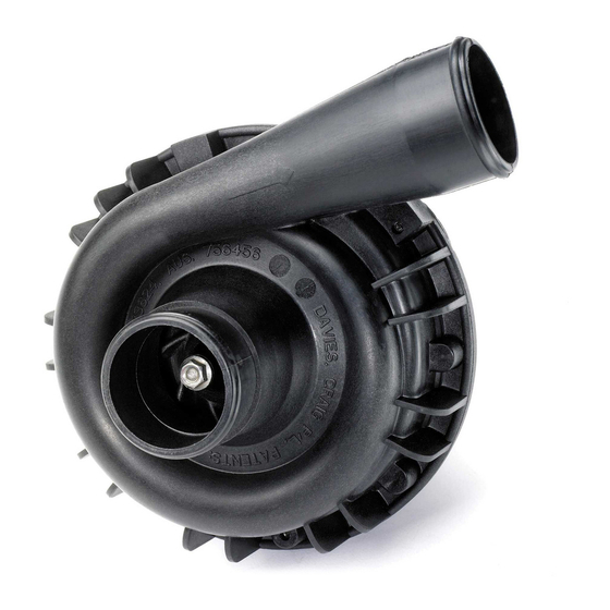
COMPONENTS:
No. Description
1. EWP Pump Assy.
2. Wiring harness with 10A fuse
3. Rubber Sleeves
4. Hose Clamps
HARDWARE COMPONENTS:
No. Description
5. Hardware bag
--Relay
--Scotch lock
--Ring Terminal
--Self Tapper
SECTION ONE: INSTALLING THE EWP
®
1. The EWP
115 is best fitted in the lower radiator hose connecting the radiator to the existing mechanical
water pump housing and let the hose hold the weight of the pump and it will dampen from vibration too.
Check the area for available space and shape of the hose. The section of radiator hose connected to the
radiator must be connected to the inlet of the electric pump and the section of radiator hose connected to the
original pump/engine block must be connected to the outlet of the electric water pump. The pump inlet is in
the centre of the pump. The EWP
from the radiator and prevent air entering the pump. Alternatively, it can be fitted in the upper hose, but in
this case the coolant level must be maintained and now the section of radiator hose connected to the top of
the radiator must be connected to the outlet of the electric pump and the section of radiator hose connected
P/No:8923
LIMITED
A.C.N. 004 918 825
AUSTRALIA
®
115 INSTALLATION INSTRUCTIONS
®
(ELECTRIC WATER PUMP) AND OPTIONS FOR PUMP CONTROL
OPERATE WITHOUT A POSITIVE 'HEAD' IN AN 'OPEN' SYSTEM.
Qty.
1
1
2
2
Qty.
1
1
1
1
1
4
®
should be positioned as low as possible to maximise the gravity feed
77 Taras Avenue
P.O. Box 363
Altona North
Vic 3025 Australia
Phone: +61(0)3 9369 1234
Fax:
+61(0)3 9369 3456
Email: info@daviescraig.com.au
Web: www.daviescraig.com.au
®
which is designed to replace or supplement the
®
can also be set to continue running
®
115
ISO 9001
Lic No 4528
Standards
Australia
®
is used to replace the
2
3
5
Advertisement
Table of Contents

Related Manuals for Davies Craig EWP-115


Summary of Contents for Davies Craig EWP-115
- Page 1 DAVIES, CRAIG 77 Taras Avenue P.O. Box 363 PROPRIETARY LIMITED Altona North A.B.N. 71 004 918 825 A.C.N. 004 918 825 Vic 3025 Australia MELBOURNE AUSTRALIA Phone: +61(0)3 9369 1234 Fax: +61(0)3 9369 3456 Email: info@daviescraig.com.au ISO 9001 Lic No 4528 Web: www.daviescraig.com.au Standards Australia...
- Page 2 to the engine block must be connected to the inlet of the electric water pump. The pump can be installed in any orientation but to assist air bleeding try to mount the outlet pointing upwards. 2. Add the rubber sleeves if necessary (Item No 3) to the inlet and outlet, if required, to suit your particular hose diameter.
- Page 3 2. Pull the pump impeller off the belt driven pump shaft. (NOTE: You may need to drill holes through the impeller close to the drive shaft to make it easier to remove.) Be careful not to damage the seal or bearing when removing the impeller.
- Page 4 INSTALLING THERMAL SWITCH (Refer wiring diagram 2) USE DAVIES CRAIG PART NO 0409 TO INSTALL THE SENSOR OR 1. When the engine is cold remove the top radiator hose at the radiator end.
- Page 5 ® WIRING DIAGRAM 2: EWP WITH THERMAL SWITCH - P/NO: 0401: RELAY & LOOM FROM PUMP PACKAGING THERMAL SWITCH PUMP MOTOR Green Blue BATTERY Earth FUSE Blue Black OPTION 3: CONTINUOUS RUNNING (Recommended for race vehicles, very hot climates, and cars running on LPG.) This option will provide maximum cooling from the pump under all conditions without controller or switch.
- Page 6 ® WIRING DIAGRAM 3: EWP CONTINUOUS RUNNING: +VE IGNITION SOURCE RELAY & LOOM FROM PUMP PACKAGING PUMP MOTOR Green FUSE Blue BATTERY Earth Black ® BLEEDING THE EWP ® Ensure the EWP is orientated correctly as shown below before continuing and hose clamps are tight. NOTE: This orientation is a temporary requirement for the purpose of bleeding the pump and ensuring there is no air entrapped within the seal housing of the pump.
- Page 7 NOTE: Loosening the hose clamps can change the pump orientation and rotating pump to desired position. If leakage occurs from hoses during re-positioning, the coolant level must be topped up. Ensure that hose clamps are tight. These installation instructions will suit most situations but there are conditions of engine design, environment, and the kind of motoring involved, which may call for other arrangements not described here.
- Page 8 ® • LPG (Liquid Petroleum Gas) vehicles require constant flow through the LPG converter and if the EWP ® is used in conjunction with the Controller, we recommend the installation of an EBP (Electric Booster Pump) to overcome freezing of the converter body at start up. •...
Need help?
Do you have a question about the EWP-115 and is the answer not in the manual?
Questions and answers