Table of Contents
Advertisement
Installation/Operator's Manual
SAFETY NOTICE
Please read entire manual before installation and use of this pellet fuel-
burning boiler. Failure to follow these instructions could result in property
damage, bodily injury or even death. Contact local building or fire
officials about restrictions and installation inspection requirements in
your area.
SAVE THESE INSTRUCTIONS
PINNACLE PB150
PELLET/CORN
BOILER
PINNACLE STOVE SALES INC
1089 HIGHWAY 97 NORTH
QUESNEL, BC V2J 7C9
TEL. (250) 992-5050
FAX. (250) 992-5850
Advertisement
Table of Contents

Subscribe to Our Youtube Channel
Related Manuals for Intertek Pinnacle PB150

Summary of Contents for Intertek Pinnacle PB150
- Page 1 Failure to follow these instructions could result in property damage, bodily injury or even death. Contact local building or fire officials about restrictions and installation inspection requirements in your area. SAVE THESE INSTRUCTIONS PINNACLE PB150 PINNACLE STOVE SALES INC 1089 HIGHWAY 97 NORTH PELLET/CORN QUESNEL, BC V2J 7C9 TEL.
-
Page 2: Table Of Contents
TABLE OF CONTENTS Page SPECIFICATIONS SPECIFICATIONS DIAGRAM figure 1 INSTALLATION REQUIREMENTS AND CLEARANCES BURNER AND CONTROLS SEQUENCE OF OPERATION PRIMARY CONTROL FUNCTIONING OF SAFETY AND OPERATING CONTROLS VENTING 9-11 VENT TERMINATION REQUIREMNETS figure 2 DAMPER CONTROLS WARNING ABOUT CHIMNEY FIRES DOMESTIC WATER SYSTEM-DIAGRAM figure 3 DOMESTIC WATER COIL REQUIREMENTS figure 4 PARALLEL SYSTEM-DIAGRAM figure 5... -
Page 3: Vent Termination Requiremnets Figure
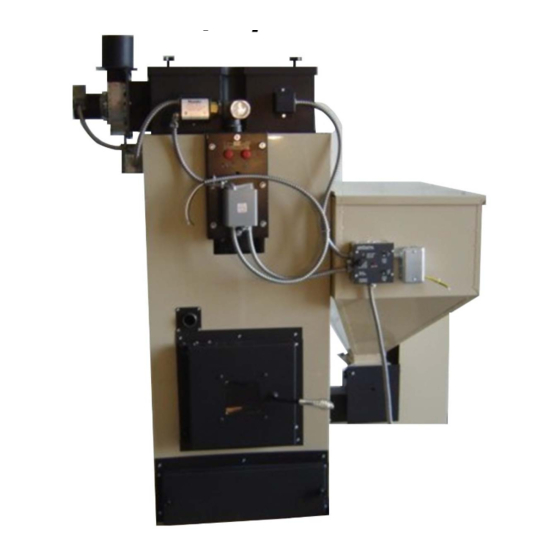
BOILER SPECIFICATIONS BTU INPUT ------------------------------------- 85,000 TO 130,000 BTU/HR EFFICIENCY (HEAT TRANSFER) --------------- 80% HEIGHT ----------------------------------------- 62” WIDTH OVERALL ------------------------------- 47” DEPTH ------------------------------------------ 29” HOPPER CAPACITY ----------------------------- 160 lbs WEIGHT ---------------------------------------- 585 lbs FLUE SIZE -------------------------------------- 4” BREACH ---------------------------------------- LEFT SIDE DOMESTIC HOT WATER COIL (GPM) --------- 5 gal (5 GPM. -
Page 4: Specifications
SPECIFICATIONS Figure 1... -
Page 5: Installation Requirements And Clearances
INSTALLATION GENERAL The PB150 hot water steel boilers are high quality pellet/corn fired heating units. The installation of the unit shall be in accordance with the regulations of the authorities having jurisdiction. FREIGHT CLAIMS All units should be inspected for damage upon arrival. Concealed damage claims should, be filed immediately against the carrier by the consignee. -
Page 6: Parallel System-Diagram Figure
openings in the door. Each opening should have a free area of not less than 1 square inch per 1,000 BTU (140 square inch per US GPH) of the total input for all appliances in the enclosure. One opening located, near top of enclosure and one near the bottom. BASEMENT Where a boiler is installed in a full basement, infiltration is normally adequate to provide air for combustion. -
Page 7: Burner And Controls
BURNER AND CONTROLS Honeywell L6081A Aquastat Controller This control is installed on the middle fitting of the domestic coil. These immersion type controls are used with forced hydronic heating systems, which include domestic water service. This model provides high limits, low limits for maintaining minimum boiler water temperature and circulator controls. -
Page 8: Primary Control
PRIMARY CONTROL 0II350S SEQUENCE OF OPERATION The Traeger 0II350S primary control is a high-tech, state of the art computer. The control performs the function of piloting the system when the 3A 250V thermostat does not call for heat. It conserves fuel consumption. -
Page 9: Functioning Of Safety And Operating Controls
FUNCTIONING OF SAFETY AND OPERATING CONTROLS The safety and operating controls shall function within the limits specified by the manufacturer for the type of equipment. The following tests shall be performed: (a) Check the operation of the automatic fuel feeding interrupt device at each entrance to the floor space within which the fuel-feeding device is installed. -
Page 10: Venting
VENTING Vent Termination Requirements: Table 1: For use with Figure 1 for allowable exterior vent termination locations. Letter Minimum Clearances Description 24 in (61 cm) Above grass, top of plants, or any other combustible materials. 48 in (122 cm) From beside/below any door or window that may be opened. 24 in (61 cm) From above any door or window that may be opened. - Page 11 VENTING Chimney required for the PB150 is 4” Class “L” (also known as PL vent). A starting collar must be used to attach the venting system to the furnace. When connecting into a Class “A” or masonry chimney a listed 4” liner MUST be used to prevent back drafting of the chimney. EXISTING CLASS “A”...
-
Page 12: Damper Controls
VENTING GENERAL- A PELLET/CORN FIRED UNIT SHALL BE CONNECTED TO A FLUE HAVING SUFFICIENT DRAFT AT ALL TIMES TO ASSURE PROPER OPERATION. 1. Only a trained experienced serviceman should attempt the installation or service of any boiler and or venting device. All venting installations must comply with the recommendations of the venting manufacturer and with all state and local codes. -
Page 13: Warning About Chimney Fires
WARNING ABOUT CHIMNEY FIRES Failing to maintain your woodstove or fireplace properly can lead to a chimney fire. Chimney fires occur when combustible deposits on the inner walls of the chimney ignite. These combustible deposits, called "creosote," are a natural by-product of wood burning. A fire hazard exists if ¼” of creosote (or more) coats the inner walls of the chimney. - Page 14 Figure 3...
- Page 15 DOMESTIC WATER COIL CONNECTION When installing the domestic water coil connection an ASME certified pressure / temperature relief valve must be installed. Install pressure temperature relief valve in the hot water supply side exiting the domestic water coil, see figure 5. Drain valve piping should be piped to a safe area for discharge.
- Page 16 Figure 5...
- Page 17 Figure 6...
-
Page 18: Wiring Information
WIRING INFORMATION All internal electrical wiring is completed at the factory. All external wiring must conform to the National Electric Code and any local codes. Line voltage leads utilize wire nut connections. A surge suppressor should be installed to protect control board. Surge suppressors are available now that mount to your breaker box providing protection to your whole house. -
Page 19: Low Water Cutoff
PB150 BOILER WIRING Power Requirements: BLACK 110 Volts Pimary Control WHITE 15 Amps max Wire through a service switch. WHITE Surge protection required. BLACK ORANGE YELLOW Low Limit Snap Disc YELLOW BLUE YELLOW Thermostat YELLOW Thermostat WHITE Low Water Cutoff BLACK YELLOW Relay... -
Page 20: Burning Corn
BURNING CORN IN THE PB150 1. The PB150 will burn most types of clean-shelled corn. It is not necessary to mix the corn with wood pellets, although some people have had good success burning a 50/50 mix. The PB150 boiler is supplied with a plug in the metering cup. -
Page 21: Start-Up Instructions
START UP INSTRUCTIONS 1. Make sure service switch to boiler is off. 2. Make sure boiler has been filled with water until entire system has been purged and desired pressure is obtained. 3. Check all fittings for leaks. 4. The PB150 boiler is supplied with a plug in the metering cup. If burning wood pellet only, this plug can be removed to increase firing rate. -
Page 22: Fuel Requirements
FUEL QUALITY Pellet quality is very important, please read the following: Your PB150 boiler has been designed to burn wood pellet or shelled corn. Do not use any other type of fuel, as this will void any warranties stated in this manual. - Page 23 MAINTENANCE UNIT MUST BE CLEANED AFTER APROXIMATELY 2 TONS OF FUEL TO ENSURE GOOD EFFICIENCY. MONITOR YOUR BOILER DAILY UNTIL EXPERIENCE SHOW HOW OFTEN CLEANING IS NECESSARY. Ensure fire is out and boiler is sufficiently cooled to allow proper cleaning. Switch primary control feed system switch to off.
-
Page 24: Alternate Connections
ALTERNATE PIPING AND WIRING CONNECTION Not all existing systems may be 100% compatible with our PB150 boiler so an alternate method of connections can be used. These installation options should be discussed with your hydronic installation specialist to insure proper operation. Primary and secondary loops A primary loop of reasonable size of at least 1-¼”... -
Page 25: Warranty
PINNACLE STOVE SALES WARRANTY NON TRANSFERABLE MODEL: _PB150 ___ SERIAL NUMBER: _________________ DATE PURCHASED: __________ FROM: _____________________ Complete Unit Warranty The manufacturer provides a warranty on all steel parts (except burn pot) and electrical components against defects in material or workmanship under normal use and maintenance for a period of one (1) year from the installation date. -
Page 26: Trouble Shooting
TROUBLE SHOOTING GUIDE Tools Essential for Trouble Shooting 1. Furnace Installation and Operation manual 2. Circuit Tester / Volt Meter 3. Molex pin Extractor 4. Volt Meter STEP #1 ATTENTION: Before attempting any trouble shooting: Check your wiring to control box to insure proper polarity and grounding. Check flue for any blockage. - Page 27 CONFIRM CUP AND AUGER MOTOR OPERATION Place a jumper wire between the leads to the safety disc located on the exhaust flange. Set the main power switch to “feed system”. Both the cup and auger motor should start now. If the motors run but the fuel metering cup and/or auger do not turn, check the cast iron couplers to make certain that the set screw is tight or that a coupler has not snapped off.
- Page 28 Let auger run for one minute. Tighten screws. Auger should realign itself. Possible build up of carbon on end of auger where it enters burn pot. Decrease in heat output PROBLEM: SOLUTION: Thoroughly clean heat exchanger. Did you start using different fuel? Shutter on draft fan moved? OPERATOR RELATED PROBLEMS PROBLEM:...
-
Page 29: Parts List Figure
PARTS LIST Figure 10 1. Hopper connector flange F000221P 8. Cup motor F000101P 2. Pillow block ball bearing F000505P 9. Manual reset F000105P 3. Cutting blades (2) ea. F000513P-2 10. Auger motor F000102P 4. Fuel metering cup F130512P 11. Auger/shaft assembly F150293P 5. -
Page 30: Notes
NOTES...
Need help?
Do you have a question about the Pinnacle PB150 and is the answer not in the manual?
Questions and answers