Table of Contents
Advertisement
Advertisement
Table of Contents

Related Manuals for Gesan DPR 100

Summary of Contents for Gesan DPR 100
-
Page 2: Table Of Contents
WELCOME BASIC SAFETY RULES INSTALLATION OF THE ELECTRICAL GENERATOR SOUND INSULATION CONTROL UNITS 3.2.1 GPM-2 Analog Control Module 3.2.2 DEEP SEA Digital Control Module 3.2.3 INTELIGEN Digital Control Module TRAILER INSTALLATION OF THE ELECTRICAL GENERATOR UNLOADING AND TRANSPORT 12 - 13 INSTALLATION OF PORTABLE UNITS 4.2.1 Placement... -
Page 3: Welcome
Should you have any problem with the equipment provided, please contact the distributor directly. GRUPOS ELECTRÓGENOS GESAN, S.A., as a part of its dedication to constant product improvement, will revise its manuals and incorporate the improvements made to supplied units. Thus the information contained in this document is subject to change without prior notice and without obligation to update. -
Page 4: Basic Safety Rules
2.- BASIC SAFETY RULES Safety precautions and recommendations for handling the electrical generator supplied by GESAN. Do not allow the unit to be used by non-authorized personnel or by minors without adult supervision. Use the necessary Individual protection equipment. Ground the machine. -
Page 5: Installation Of The Electrical Generator
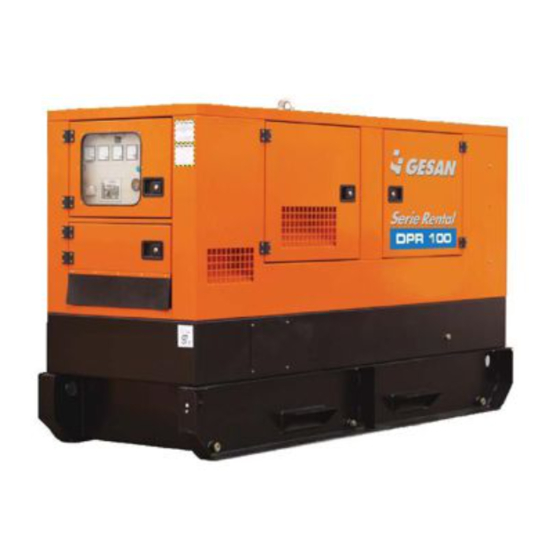
3.- INSTALLATION OF THE ELECTRICAL GENERATOR General overview of the electrical generator and its different configurations manufactured by GRUPOS ELECTRÓGENOS GESAN, S.A. Note: this image corresponds to the detailed view of Image 2 Image 1- ELECTRICAL GENERATOR WITH CANOPY AND OPTIONAL TRAILER FOR UNITS WITHOUT DRIP PAN. - Page 6 Image 2 - DETAILED VIEW OF IMAGE 1 Electrical panel door Coolant tank hatch Ventilation grill Side access door Lifting frame and eyebolt Fuel tank cap Electrical control panel Smoke exhaust Alternator Engine Electrical power panel Antivibration feet Battery Fuel tank Base frame Retention bath Capot...
-
Page 7: Sound Insulation
3.1.- SOUND INSULATION The supplied unit is soundproofed and includes sound-insulating canopy. See details on part 11 Image 3 - INTERIOR OF A SOUNDPROOFED ELECTRICAL GENERATOR... -
Page 8: Control Units
3.2 .- CONTROL UNITS The unit provided may be controlled by different modules depending on the type of function it has been designed to perform. The following is a generic control panel, which contains all of the electrical and mechanical options available. Image 4 - GENERIC CONTROL PANEL... -
Page 9: Gpm-2 Analog Control Module
3.2.1.- GPM-2 analog control module If you purchased a generator unit with a GPM-2 control module, the electrical panel will look like the following diagram: Image 5 - CONTROL PANEL FOR THE GPM-2 CONTROL MODULE... -
Page 10: Deep Sea Digital Control Module
3.2.2.- DEEP SEA digital control module If you purchased a generator unit with a DEEP SEA control module (models 5210 and 5310), the electrical panel will look like the following diagram: ENGINE BLOCK HEATER LIGHT (YELLOW) EMERGENCY STOP ELDON XXXXXX DIAGNOSTIC BUTTON LOCK... -
Page 11: Inteligen Digital Control Module
3.2.3.- INTELIGEN Digital Control Module If you purchased a generator unit with an INTELIGEN control module, the electrical panel will look like the following diagram: AMMETER FREQUENCY METER VOLTMETER EARTH LEAKAGE LOCK CIRCUIT BREAKER HOUR METER AUTO FUEL GREEN FUEL BUTTON REFILL SWITCH (OPTIONAL) -
Page 12: Trailer
3.3 .- TRAILER The generator can be supplied with a trailer for transporting the unit. • Site Trailer: for private-use areas only. Includes DIN hitch ring, safety brake and jockey wheel. * Note: Ask about the possibility of using trailer with drip pan. Image 8 - TRAILER... -
Page 13: Installation Of The Electrical Generator
4.- INSTALLATION OF THE ELECTRICAL GENERATOR 4.1 .- UNLOADING AND TRANSPORT The unloading and transport of the unit should only be done by qualified personnel, observing certain minimum safety conditions. • The ground must be capable of supporting the full weight of the Generator and the forklift. •... - Page 14 If your unit includes a trailer, one of the following may apply: • Trailer 1 - Site trailer: Connected with a DIN hitch ring and safety chains to the rear of the towing vehicle. Use of this trailer is not authorized on public roads. Use the safety brake whenever necessary. •...
-
Page 15: Installation Of Portable Units
4.2 .- INSTALLATION OF PORTABLE UNITS Portable units are defined as those moved to different work sites at least twice yearly. 4.2.1.- Placement This type of unit must be installed in well ventilated areas in order to ensure sufficient flow of coolant air and preventing combustion smoke from sitting in the engine’s exhaust. -
Page 16: Storage
4.3.- STORAGE If you think your generator will be inactive for a long period of time, follow these instructions: Press STOP on the control module. Press the emergency stop button to avoid future involuntary startups when connecting. Empty the fuel tank. Make sure the internal protection valve is in the correct position. Leave the battery disconnected. -
Page 17: Operation Manual
6.- OPERATION MANUAL The generator you purchased has been designed for manual service and thus starting and stopping the unit will be done manually. The following is a description of the different elements, according to the electrical generator chosen. 6.1.- ELECTRICAL PANEL COMPONENTS AMMETER: Measures the Intensity (A), by means of a switch, of the different phases of the electrical generator. - Page 18 EMERGENCY STOP BUTTON: Pressing this button brings the electrical generator to an immediate stop. To cancel, turn to the left, when the end of the emergency situation has been confirmed. On soundproofed units the emergency stop button is installed apart from the electrical panel (built into the canopy).
-
Page 19: Gpm-2 Analog Control Module
6.2.- GPM-2 ANALOG CONTROL MODULE Image 10 - GPM-2 CONTROL MODULE... - Page 20 NUMBER SYMBOL DESCRIPTION IDENTIFICATION Flashing red light: three failed startup Unit startup failure / attempts. alternator failure. Continuous red light: voltage failure or low frequency. Flashing red light: battery charge Battery charge alternator alternator failure . failure. Continuous red light (unit stopped): indicates contact.
- Page 21 • Startup: When the key is turned to Manual Mode position, LED indicators for low oil level (3), battery charge alternator (2)), and preheating (9) will be turned on and after 10 seconds the LED indicator (9) will be turned off, at which point the START button (13) can be pressed to start up the unit.
- Page 22 ALARMS: The following is a chart describing the possible alarms of the GPM-2 module: NUMBER SYMBOL DESCRIPTION IDENTIFICATION If the light is flashing, an audible signal Unit startup failure. will be given and generator is shut down. If light is continuous, indicates low Alternator failure.
-
Page 23: Deep Sea 5210 Digital Control Module
6.3.- DEEP SEA 5210 DIGITAL CONTROL MODULE Image 11 - DEEP SEA 5210 CONTROL MODULE Image 12 - DEEP SEA 5210 CONTROL MODULE... - Page 24 NUMBER SYMBOL DESCRIPTION IDENTIFICATION Stop button. Green LED Control module connection. MANUAL mode button. Green LED Settings - Settings + AUTOMATIC mode button. Green LED Settings: ENTER. Startup button for Electrical generator. When lit, indicates correct readings for Green LED electrical generator.
- Page 25 • Startup: If the LCD screen is off, press (1) to connect the control module and the LCD screen will turn on. Press the button (2) and the LED in the top part of the button will turn on, indicating that the unit is operating.
- Page 26 ICON DESCRIPTION Indicates that the screen display information refers to the electrical generator. Indicates that the event log reading is being accessed (Flashing). Indicates that the programming mode is being accessed. Indicates that the electrical generator is idle. Indicates that the electrical generator’s system date and time is being shown.
- Page 27 To view the different parameter readings, press , and the LCD indicator (8) will display these readings in the following order: - RPM of generator / frequency (Hz). - Line-Neutral AC voltage of generator. - Line-Line AC voltage of generator. - Oil pressure.
- Page 28 ALARMS: The following chart describes each alarm: NUMBER SYMBOL DESCRIPTION Fuel level below minimum. Low battery voltage. Emergency stop. Engine overspeed. Low oil pressure. High engine temperature. If engine does not start after 3 attempts, the unit will be stopped and this icon will be displayed.
- Page 29 - Event log: To view the event log, press the following button repeatedly (10). This icon will flash A screen similar to this will be shown: 2002 11.01 8.17 “On november 1, 2002, at 08:17, the system detected that the oil pressure was below the minimum level and shut down the generator.”...
- Page 30 LIST OF POSSIBLE ALARMS: Low pressure Energize to stop High temperature Low voltage Fuel level (%) High voltage Date / time Low frequency Mains transient delay High frequency Start delay Generator under voltage L1-N Warming up Generator over voltage Crank attempt Generator under frequency Crank rest Generator over frequency...
-
Page 31: Deep Sea 5310 Digital Control Module
6.4.- DEEP SEA 5310 DIGITAL CONTROL MODULE RUNNING IN AUTO RUNNING IN AUTO Warming 10s Warming 10s L-N 240V DA 50Hz L-N 240V DA 50Hz L-L 415V OKW L-L 415V OKW Image 13 - DEEP SEA 5310 CONTROL MODULE... - Page 32 NUMBER SYMBOL DESCRIPTION IDENTIFICATION Stop button. Green LED MANUAL mode button. Green LED Settings - Settings + AUTOMATIC mode button. Green LED Settings: ENTER. Button to silence alarms / control Green LED module LED test. Button for starting up electrical generator.
- Page 33 • Startup: If the LCD screen is off, press (1) ) to connect the control module and the LCD screen will turn on. Press the button (2) and the LED in the top part of the button will turn on, indicating that the unit is operating. Press (5) to start up the unit.
- Page 34 ALARMS: Press (5) to silence the audible alarm and the common alarm LED. By default, the information screen will display the following message: Running in auto Generator on load L-N 230v 240A 50Hz L-L 400v 133kW If an alarm occurs, the screen will display the following: Alarm Alarm type.
- Page 35 INCIDENT ALARM DESCRIPTIONS ALARM Battery charge alternator voltage not detected. Warning Charge fail ALARM Warning Low battery volts Battery voltage beyond established limits. ALARM Warning High battery volts ALARM After shutdown command, engine continues running. Could also indicate faulty oil pressure sender. Fail to stop ALARM Low fuel level.
- Page 36 INCIDENT DESCRIPTION OF SHUTDOWNS ALARME Engine does not start, three attempts made. Shutdown Failed to start ALARME Controlled shutdown of the unit. It will not be functional until the emergency stop button Shutdown has been reset. Emergency stop ALARME Low oil pressure. Shutdown Low oil pressure ALARME...
- Page 37 - Typical information screen messages: Indicates electrical generator running normally in automatic mode. Also indicates the Running in auto average line to neutral voltage (L-N), the highest of the three phase currents, the Generator on load nominal frequency, average line-to-line voltage (L-L) and total kilowatts. L-N 230V 240A 50Hz L-L 440V 133kW - Measurement parameter display screens:...
- Page 38 - Displaying information: Press this button: (11). Page order: - Status display. - Instrument display. Alarms display. Event log. It is possible to scroll through the different display screens by pressing the next page button: (10). Once selected, the instrument will remain on the screen until the user selects a different instrument or after a period of inactivity for the control module, at which point the default display appears.
- Page 39 - Alarm LED: Remote start on load Overload pre-alarm Common Common - Editing the current date and time: The date and time are adjustable. When the battery is disconnected, the date and time are frozen; when the battery is reconnected, the date and time shown will be from the time the battery was disconnected. The date and time reflected in the event Log will be taken from the configuration according to the following stepst: Press (1) and...
- Page 40 Press the button (10) to confirm the value entered and select the day. The day will begin to flash. Press (3) or (2) again to adjust to the desired setting. Press the (10) button to confirm the selection made and select the month. The value will start to flash. Press (3) or (2) again to adjust the month.
-
Page 41: Inteligen Digital Control Module
6.5.- INTELIGEN DIGITAL CONTROL MODULE 14 13 Image 14 - INTELIGEN CONTROL MODULE... - Page 42 NUMBER SYMBOL DESCRIPTION IDENTIFICATION Horn reset Deactivates audible alarm. OFF←MAN←AUT←TEST Scrolls through different operating Mode Mode modes. OFF→MAN→AUT→TEST Fault reset Fault reset. Acknowledges faults and alarms. Start Start button. In manual mode. Stop Stop button. In manual mode. Green if unit voltage is present Generator voltage present.
- Page 43 The InteliGen module contains the following three menu screens: - Measurement Page - Adjustment Can be selected using the following button (18). - History To display the different instruments on each screen menu, press (17) and (16). The measurement screen displays the parameters measured by the engine; if the engine uses an electronic management system, many additional parameters can be displayed.
- Page 44 • Startup: Start Press the START button (5) to start up the electrical generator. When the generator voltage is within the established limits, the LED indicator (7) will be lit. Next press the GCB ON/OFF button (10). The loads Stop will be transferred directly to the electrical generator.
-
Page 45: Maintenance Of Electrical Generator
7.- MAINTENANCE OF ELECTRICAL GENERATOR You must make sure that the person who will perform this duty is qualified to do so and utilizes the appropriate individual protection equipment. 7.1.- PRIOR TO MAINTENANCE You must first: • Switch control module to the STOP position. •... -
Page 46: Maintenance Chart
7.3.- MAINTENANCE CHART FREQUENCY MAINTENANCE OPERATION AFTER 50 HRS. • Perform 250 hr. maintenance. • Check fuel level on the main tank. • Check coolant fluid level. • Check the oil level (see engine’s user manual). • Drain water separator filter. •... -
Page 47: Troubleshooting
8.- TROUBLESHOOTING INCIDENT LIKELY CAUSE SOLUTION Defective battery. Replace the battery. Starter does not turn. Battery isolator open. Close battery isolator. Defective starting system. Contact technical services. Faulty voltage detector on control Contact technical services. module. Starter functioning properly. Lacking fuel. Refill the fuel tank. -
Page 48: Warranty
The electrical generator warranty covers an entire year, starting from the date it is installed. This should be communicated to GRUPOS ELECTRÓGENOS GESAN, S.A. (hereinafter “the manufacturer”), in writing, via fax or email. The following information must be included: MODEL, SERIAL NUMBER and INSTALLATION DATE. -
Page 49: Noise Level
11.- NOISE LEVEL GESAN Electrical Generators produce different acoustic levels depending on the output and soundproofing of the electrical generator. The noise output is indicated on a sticker affixed to the unit’s base frame. Each electrical generator is provided with a sticker indicating the level of noise output produced (see APPENDIX 1 - FIGURES). -
Page 50: Declaration Of Conformity
12.- DECLARATION OF CONFORMITY GRUPOS ELECTRÓGENOS GESAN, S.A., shall deliver a CE “Declaration of conformity” form along with the unit, in compliance with the referenced regulations or standardized documents. 13.- APPENDIX 1: FIGURES Detail of the unit’s nameplate: PR060300 Model... - Page 51 LABELED ITEM DESCRIPTION D => Engine uses diesel fuel at 1,500 rpm. P => Engine manufacturer is (P)erkins, (V)olvo, (C)ummins or Deut(Z). DPR 100 R => The electrical generator is soundproofed rental series. 100 => Commercial name. 400/230 V Indicates electrical generator output voltage.
- Page 52 IMPORTANT CAUTION PLACING IN OPERATION: THIS ELECTRICAL 1. Make sure “Battery Isolator” switch is CLOSED. GENERATOR COULD 2. Check engine’s water and oil levels. START UP WITHOUT PRIOR 3. Connect ground wires to a suitable point on the ground. WARNING. 4.
-
Page 53: Appendix 2: Image Index
14.- APPENDIX 2: IMAGE INDEX ELECTRICAL GENERATOR WITH CANOPY AND OPTIONAL TRAILER FOR Image 1 UNITS WITHOUT DRIP PAN Image 2 DETAILED VIEW OF IMAGE 1 Image 3 INTERIOR OF A SOUNDPROOFED ELECTRICAL GENERATOR Image 4 GENERIC CONTROL PANEL Image 5 CONTROL PANEL FOR THE GPM-2 CONTROL MODULE Image 6 CONTROL PANEL FOR THE DEEP SEA CONTROL MODULE... - Page 54 GRUPOS ELECTROGENOS GESAN S.A. Polígono Malpica-Alfindén, c/Encina, nº 8 Teléfono +34 976 107 332 • Fax +34 976 107 366 50171 LA PUEBLA DE ALFINDÉN (Zaragoza) ESPAÑA www.gesan.com • export@gesan.com • info@gesan.com...
Need help?
Do you have a question about the DPR 100 and is the answer not in the manual?
Questions and answers