Table of Contents
Advertisement
Advertisement
Table of Contents
Troubleshooting

Related Manuals for Shenzhen PM-9000 Express

Summary of Contents for Shenzhen PM-9000 Express
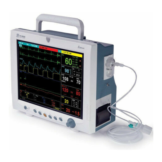
- Page 1 PM-9000 Express Patient Monitor Service Manual...
- Page 3 Copyright Statement SHENZHEN MINDRAY BIO-MEDICAL ELECTRONICS CO., LTD. (hereinafter called Mindray) owns all rights to this unpublished work and intends to maintain this work as confidential. Mindray may also seek to maintain this work as an unpublished copyright. This publication is to be used solely for the purposes of reference, operation, maintenance, or repair of Mindray equipment.
- Page 4 Service Manual (V 1.0) adjusting the volume to very low or completely muting the sound may result in the disaster to the patient. The most reliable way of monitoring the patient is at the same time of using monitoring equipment correctly, manual monitoring should be carried out.
- Page 5 Safety, Reliability and Performance Mindray is not responsible for the effects on safety, reliability and performance of the PM-9000 Express Patient Monitor if: ■ assembly operations, extensions, re-adjusts, modifications or repairs are carried out by persons other than those authorized by Mindray.
- Page 6 Freight policy. The customer is responsible for freight charges when equipment is shipped to Mindray for service (this includes customs charges). Company Contact Manufacture: Shenzhen Mindray Bio-Medical Electronics Co., Ltd. Address: Mindray Building, Keji 12th Road South, Hi-tech Industrial Park, Nanshan, Shenzhen, P.R.China,518057...
-
Page 7: Safety Precautions
Service Manual (V 1.0) Safety Precautions 1. Meaning of Signal Words DANGER, WARNING , and In this manual, the signal words are used CAUTION regarding safety and other important instructions. The signal words and their meanings are defined as follows. Please understand their meanings clearly before reading this manual. Signal word Meaning Indicates an imminently hazardous situation which, if not... - Page 8 Service Manual (V 1.0) current at power ON, the circuit breakers and fuses of the building’s supply circuit may be tripped. CAUTION: 1. Malfunctions due to radio waves (1) Use of radio-wave-emitting devices in the proximity of this kind of medical electronic system may interfere with its operation. Do not bring or use devices which generate radio waves, such as cellular telephones, transceivers, and radio controlled toys, in the room where the system is installed.
- Page 9 Service Manual (V 1.0) Symbols Be Careful Protective earth ground Indicates that the instrument is IEC-60601-1 Type CF equipment. The unit displaying this symbol contains an F-Type isolated (floating) patient applied part providing a high degree of protection against shock, and is suitable for use during defibrillation. Equipotential grounding terminal CE mark 93/42/EEC a directive European...
-
Page 11: Table Of Contents
Service Manual (V 1.0) Contents CHAPTER 1 ABOUT THE PRODUCT ...................1 ........................1 NTRODUCTION ..........................1 PPLICATION .........................3 NVIRONMENT CHAPTER 2 PRINCIPLES........................4 ..........................4 ENERAL ......................5 ARDWARE ESCRIPTION ......................17 OFTWARE ESCRIPTION ......................19 YSTEM ARAMETER CHAPTER 3 PRODUCT SPECIFICATIONS................25 .......................25 AFETY LASSIFICATIONS ...................26 NVIRONMENTAL PECIFICATIONS .....................27 OWER... - Page 12 Service Manual (V 1.0) CHAPTER 6 MAINTENANCE AND CLEANING ................66 ........................66 AINTENANCE ..........................66 LEANING ......................66 LEANING EAGENT ........................67 TERILIZATION .........................67 ISINFECTION...
-
Page 13: Chapter 1 About The Product
Chapter 1 About the Product 1.1 Introduction The PM-9000 Express Patient Monitor, a portable and accessible patient monitor, is supplied by rechargeable batteries or external AC power, which applies to adults, pediatric and neonates. You can select different configurations as required. Besides, the PM-9000 Express can be connected with the central monitoring system whereby a monitoring network will be formed. - Page 14 Usually, patient monitors are seen in some clinical areas in hospital, such as ICU, CCU, intensive care units for heart disease patients, operating rooms, emergency departments and observation wards. They can also be used in clinics. The PM-9000 Express patient monitor should be run under the control of clinical staff.
-
Page 15: Environment
Minimum Alveolar Concentration (MAC) 4 AG waveforms (CO O, O , AA) The PM-9000 Express provides the functions of audio/visual alarm, trend graphic storage and output, NIBP measurement, alarm event identification, large font screen, defibrillator synchronization, oxyCRG recall, drug calculation, etc. 1.3 Environment 1.3.1 Temperature... -
Page 16: Chapter 2 Principles
Main control part; Man-machine interface; Power supply; Other auxiliary functions; These functional units are respectively detailed below. Figure 2-1 Structure of the PM-9000 Express 2.1.1 Parameter Measurement The parameter measurement and monitoring are the core functions of the patient monitor. The... -
Page 17: Hardware Description
2.1.2 Main Control Part In the PM-9000 Express patient monitor, the main control part refers to the main control part of the main control board. It drives the man-machine interface, manages the parameter measurement and provides users with other special functions, such as storage, recall of waveforms and data. - Page 18 Chapter 2 Principles Figure 2-2 Functional structure of the PM-9000 Express...
- Page 19 Chapter 2 Principles The PM-9000 Express PCB connection is shown in the following figure. Figure 2-3 PCB connection Basic functions and working principles of modules are described in the following sections. 2.2.1 Main Board 2.2.1.1 General The main board is the heart of the patient monitor. It implements a series of tasks, including the system control, system scheduling, system management, data processing, file management, display processing, printing management, data storage, system diagnosis and alarm.
- Page 20 Chapter 2 Principles 2.2.1.2 Principle diagram Figure 2-4 Working principle of the main board 2.2.1.3 Principle The main board is connected with external ports, including the power input port, multi-way serial port, TFT display interface, analog VGA interface, network port and analog output port. Besides, on the main board is also a BDM interface reserved for the software debugging and software downloading.
- Page 21 Chapter 2 Principles In addition, FPGA also extends multiple serial ports, which communicate with peripheral modules. FPGA transfers the received data to CPU through the bus; CPU delivers data to FPGA through the bus, and then the FPGA transfers those data to the peripheral modules.
- Page 22 Chapter 2 Principles rejects the common-mode interference signal. The low-pas filtering circuit filters the high-frequency interference signal beyond the frequency band of the ECG signal. The PACE signal refers to the ECG pace signal. It has significant interference to the ECG signal detection.
- Page 23 Chapter 2 Principles 2.2.3 CO/IBP Module 2.2.3.1 General This module provides the function of measuring two parameters: Cardiac Output (CO) and Invasive Blood Pressure (IBP). 2.2.3.2 Principle diagram Figure 2-6 Working principle of the CO/IBP module 2.2.3.3 Principle This module collects the CO/IBP signal through the transducers, processes it and sends it to the main board throgh the serial port.
- Page 24 Chapter 2 Principles 2.2.4 Module 2.2.4.1 General This module provides the function of measuring the Pulse Oxygen Saturation (SPO 2.2.4.2 Principle diagram Figure2-7 Working principle of the SpO module 2.2.4.3 Principle The SpO measurement principle Collecting the light signal of the red light and infrared transmitting through the finger or toe which is pulsing;...
- Page 25 Chapter 2 Principles Implementing the logical control of all the circuits; Implementing the data processing for the SpO parameter; Implementing the communication with the main board. Power & Signal isolate Circuit Isolating the external circuits to ensure the safety of human body; Supplying power for all circuits;...
- Page 26 Chapter 2 Principles Motor Drive Circuit This circuit controls the action of the air pump. It, together with the Valve Drive Circuit, implements the inflation and deflation of the cuff. Besides, it provides the status signal of the motor for the A/D conversion part. NIBP Signal Process Network The NIBP signal is the differential input signal.
- Page 27 Chapter 2 Principles matrix data, sends them to the heat-sensitive printer, and drives the printer. Step Motor Drive Circuit There is a step motor on the heat-sensitive printer. The step motor drives the paper. This circuit is used to drive the step motor. Printer Status Detect Circuit This circuit detects the status of the heat-sensitive printer, and sends the status information to the CPU system.
- Page 28 Chapter 2 Principles Controlling the status of LED; Controlling the audio process circuit; Regularly resetting the Watchdog timer; Communicating with the main board. Audio Process Circuit This circuit generates audio signals and drives the speaker. Watchdog When powered on, the Watchdog provides the reset signal for CPU. The patient monitor provides the watchdog timer output and voltage detection functions.
-
Page 29: Software Description
Chapter 2 Principles boards. 12V DC/DC This part converts the DC voltage to the stable 12V DC voltage and supplies it for the external boards. Power Switch Circuit This circuit controls the status of the 5V DC/DC part and the 12V DC/DC part, thus to control the switch of the patient monitor. - Page 30 Chapter 2 Principles 2.3.2 System Task Task Function Period In case of a System initialization Initializing the system startup Data processing Analyzing and saving the data 1 second Display timer Implementing the timed refreshing 1 second information In case of a Switchover of modules Switching over between waveforms and screen change...
-
Page 31: System Parameter
Chapter 2 Principles 2.3.3 System Function The system tasks can be classified as follows. Figure 2-13 System task System Parameter 2.4.1 General For the PM-9000 Express patient monitor, signals are collected by modules, and the results... - Page 32 The parameter monitoring functions are described respectively in the following sections. 2.1.1 ECG/RESP ■ The PM-9000 Express patient monitor has the following ECG functions: 1) Lead type: 3-lead, 5-lead, 12-lead 2) Lead way: 3-lead (1 channel): I, II, III...
- Page 33 RESP ■ The PM-9000 Express patient monitor measures the RESP based on the impedance principle. While a man is breathing, the action of the breast leads to impedance changes between RL and LL. Change the high-frequency signal passing the RL and LL to...
- Page 34 Chapter 2 Principles of the patient; 2) Manual/Auto/Continuous mode: The manual measurement is also called single measurement; in this mode, only one measurement is done after being started. In the auto measurement mode, the measurement can be done once within the selected period, with the interval being 1, 2, 3, 4, 5, 10, 15, 30, 60, 90, 120, 180, 240 or 480 minutes.
- Page 35 Chapter 2 Principles algorithm. 2.4.7 CO measurement principle: The thermal dilution method is widely used in the clinical CO monitoring. Introduce a floating catheter into the pulmonary artery through the right atrium, and inject the physiological saline into the right atrium through the catheter whose front end is connected to the temperature transducer.
- Page 36 Chapter 2 Principles gases, multiple infrared filters are required in the AG module. The oxygen does not absorb the infrared within the above-mentioned wave band. Therefore, the oxygen is measured based on its paramagnetism. Inside the transducer of the O module, there are two crystal balls full of nitrogen.
-
Page 37: Chapter 3 Product Specifications
Chapter 3 Product Specifications Chapter 3 Product Specifications 3.1 Safety Classifications Class I with internal electric power supply. Type of protection against Where the integrity of the external protective earth (ground) in electric shock the installation or its conductors is in doubt, the equipment shall be operated from its internal electric power supply (batteries) Monitor: Degree of protection... -
Page 38: Environmental Specifications
Chapter 3 Product Specifications 3.2 Environmental Specifications 0 to 40℃ 5 to 35℃ (With Mindray CO module) Operating temperature 10 to 40℃ (With Welch Allyn CO module) 5 to 35℃ (With Oridion CO module) 10 to 35℃ (With AION AG module) Operating humidity 15 to 95%, noncondensing -500 to 4600m (-1640 to 15092 feet) -
Page 39: Power Source Specifications
Chapter 3 Product Specifications 3.3 Power Source Specifications AC mains Input voltage 100 to 240V Frequency 50/60Hz Power 140VA Fuse T 3A Internal battery Number of batteries Type Sealed lead-acid battery or lithium-ion battery Time to shutdown 5 to 15min (after the first low-power alarm) Sealed lead-acid battery Nominal voltage 12VDC... -
Page 40: Hardware Specifications
Chapter 3 Product Specifications 3.4 Hardware Specifications Physical Size 318 × 270 × 137mm (width×height×depth) Different due to different configurations Weight Standard configuration: 4.7kg Maximum weight: ≤ 7.5kg Display Type Color TFT LCD Size 12.1 inches (diagonal) Resolution 800×600 pixels Recorder Type Thermal dot array... -
Page 41: Wireless Network
Chapter 3 Product Specifications pressed. 7 buttons: POWER, MAIN, FREEZE, PAUSE, RECORD, Button NIBP, MENU Connectors Power supply 1 AC power connector Parameter ECG, RESP, TEMP, SPO2, NIBP, IBP, CO, CO2, AG Network 1 standard RJ45 network connector, 100 BASE-TX 1 standard color VGA monitor connector, 15-PIN D-sub Auxiliary output 1 BNC connector... -
Page 42: Data Storage
Chapter 3 Product Specifications 3.6 Data Storage Long trend: 96 hours, resolution 1min, 5 min or 10 min. Trend data Short trend: 1 hour, resolution 1 s or 5 s. 70 alarm events and associated waveforms (with user Alarm events selectable waveform length 8s, 16 or 32). -
Page 43: Signal Output Specifications
Chapter 3 Product Specifications 3.7 Signal Output Specifications Meets the requirements of EC60601-1 for short-circuit Standards protection and leakage current Output impedance 50Ω ECG analog output 0.05 to 100Hz(12-lead: 0.05 to Diagnostic mode: Bandwidth 150Hz) Monitor mode: (-3dB; reference 0.5 to 40Hz frequency: 10Hz) Surgery mode: 1 to 20Hz... -
Page 44: Ecg Specifications
Chapter 3 Product Specifications 3.8 ECG Specifications 3-lead (1 channel): I, II, III Lead type 5-lead (2 channels): I, II, III, aVR, aVL, aVF and V 12-lead (8 channels): I, II, III, avR, avL, avF, V1-V6 Lead naming style AHA, EURO 1.25mm/mV (×0.125), 2.5mm/mV (×0.25), 5mm/mV (×0.5), Sensitivity selection 10mm/mV (×1), 20mm/mV (×2) and auto... - Page 45 Chapter 3 Product Specifications Meets the requirement of ANSI/AAMI EC13-2002: Section 4.1.2.1 f). Response time to heart rate Less than 11 sec for a step increase from 80 to 120 BPM changes Less than 11 sec for a step decrease from 80 to 40 BPM When tested in accordance with ANSI/AAMI EC13-2002 Section 4.1.2.1 g, the response time is as follows.
-
Page 46: Resp Specifications
Chapter 3 Product Specifications 3.9 RESP Specifications Measurement technique Thoracic impedance Lead Optional: lead I and lead II; default lead II Differential input > 2.5MΩ impedance Respiration impedance test 0.3 to 3Ω range Excitation current < 300µA Baseline impedance range 200 to 2500Ω... -
Page 47: Pecifications
Chapter 3 Product Specifications 3.10 SpO Specifications Mindray SpO Module Measurement range 0 to 100% Resolution 70 to 100%: ±2 % (adult/pediatric, non-motion conditions) 70 to 100%: ±3 % (neonate, non-motion conditions) Precision ±3 % (in motion conditions) 70 to 100%: Undefined. - Page 48 Chapter 3 Product Specifications Measurement range 25 to 240bpm Resolution 1bpm ±3bpm (non-motion conditions) Precision ±5bpm (in motion conditions) Refreshing rate Nellcor SpO Specifications Sensor Range Precision* 70 to 100% ±2% MAX-A, MAX-AL, MAX-N, MAX-P, MAX-I and MAX-FAST 0% to 69% Undefined 70 to 100% ±2.5%...
-
Page 49: Ibp Specifications
Chapter 3 Product Specifications 3.11 IBP Specifications Measurement technique Auto oscillation Displayed parameters Systolic pressure, diastolic pressure and mean pressure Mode of operation Manual, auto and continuous Measurement interval in 1/2/3/4/5/10/15/30/60/90/120/180/240/480 minutes auto mode Measurement time in 5 minutes continuous mode mmHg Adult Pediatric... -
Page 50: Temp Specifications
Chapter 3 Product Specifications 3.12 TEMP Specifications Number of channels Displayed parameters T1, T2 and TD Measurement range 0 to 50°C (32 to 122°F) Resolution 0.1°C 0.1°C (excluding the sensor) Precision ±0.2°C (including the YSI 400 series sensor) Update period Body surface: <... -
Page 51: Ibp Specifications
Chapter 3 Product Specifications 3.13 IBP Specifications Number of channels Pressure labels ART, PA, CVP, RAP, LAP, ICP, P1 and P2 0 to 300 mmHg – 6 to 120 mmHg Measurement range CVP/RAP/LAP/ICP – 10 to 40 mmHg P1/P2 – 50 to 300 mmHg Resolution 1 mmHg Precision... -
Page 52: Co Specifications
Chapter 3 Product Specifications 3.14 CO Specifications Measurement technique Thermal dilution Calculated parameter CO, hemodynamics 0.1 to 20l/min Measurement range 23 to 43°C 0 to 27°C 0.1 l /min Resolution 0.1°C TB, TI: ±5% or ± 0.1 l /min Precision 0.1°C TB, TI: Alarm range... -
Page 53: Co 2 Specifications
Chapter 3 Product Specifications 3.15 CO Specifications Measurement technique Infrared absorption technique Measurement mode Sidestream, microstream or mainstream (optional) Displayed parameter EtCO2, FiCO2, Respiration Rate CO2 function Meet the requirements of EN864 and ISO9918. Mindray CO Specifications CO2 measurement range 0 to 99mmHg 0 to 40 mmHg: ±2mmHg... - Page 54 Chapter 3 Product Specifications * Conditions for measurements in typical precision: The measurement is started after the preheating mode of the module; Ambient pressure: 750mmHg to 760mmHg; room temperature: 22 to 28 ; ℃ ℃ The gas under test is dry, and the balance gas is N2; The deflation rate is 150ml/min, the respiration rate is no greater than 30BrPM, with a fluctuation less than ±3BrPM, and the inhale interval/exhale interval is 1:2;...
- Page 55 Chapter 3 Product Specifications Welch Allyn CO Specifications CO2 measurement range 0 to 99mmHg 0 to 40 mmHg: ±2mmHg Precision* 41 to 76 mmHg: ±5% 77 to 99 mmHg: ±10% Resolution 1mmHg Refreshing rate < 80s (ambient temperature: 25 ; preheating power of ℃...
-
Page 56: Ag Specifications
Chapter 3 Product Specifications 3.16 AG Specifications Measurement technique Infrared absorption Measurement mode Side stream Meets requirements of ISO9918, ISO11196, EN12598 and AG functions ISO7767 45 seconds (warming-up status) Warm-up time 10 minutes (ready-to-measure status) Adult/Pediatric 120, 150, 200 ml/minute (user-selectable) Sampling flow (sidestream) Neonatal... - Page 57 Chapter 3 Product Specifications ±0.4 5 to 10 ±0.6 10 to 15 ±1 15 to 18 >18 Not specified ±0.15 0 to 1 ±0.2 1 to 5 ±0.4 5 to 8 > 8 Not specified ±0.15 0 to 1 ±0.2 Enf, Iso, Hal 1 to 5 >...
- Page 58 Chapter 3 Product Specifications water trap and adult HAL, ISO, SEV, DES 300 ms DRYLINE™ sampling 350 ms line (2.5m) Delay time < 4s...
-
Page 59: Chapter 4 Disassembling/Assembling & Troubleshooting
Chapter 4 Disassembling/Assembling & Troubleshooting Chapter 4 Disassembling/Assembling & Troubleshooting 4.1 PM-9000 Express Disassembling/Assembling 4.1.1 Exploded View of PM-9000 Express Figure 4-1 Exploded view of PM-9000 Express Material code Part & Specification Quantity 9201-30-35947 Front cover assembly 9210-30-30181 Back plate assembly... - Page 60 Chapter 4 Disassembling/Assembling & Troubleshooting 4.1.2 PM-9000 Express Display (TFT Display) Assembly Figure 4-2 PM-9000 Express display (TFT display) assembly Standard Name & Specification Quantity M04-004015--- Cross-head screw M3×8 0010-10-12271 LG display LB121S02 9210-20-30180 12.1`back plate-LG 9210-30-30169 LVDS-TTL adapter board...
- Page 61 Chapter 4 Disassembling/Assembling & Troubleshooting 4.1.3 PM-9000 Express Support Assembly (Lithium Battery) (9201-30-35944) Figure 4-3 PM-9000 Express support assembly Material Code Part & Specification Quantity M04-004012--- Gasketed cross-head screw M3*6 9200-20-10689 Recorder regulating panel 9200-20-10485 Printer mounting plate M04-005005--- Cross-head sunk screw M3*6...
- Page 62 Chapter 4 Disassembling/Assembling & Troubleshooting 9201-20-36012 Power PCB insulating plate 9201-30-35901 Lithium battery power PCB 9210-30-30163 Socket assembly 9201-30-35908 Microstream CO adapter board 9201-30-35955 Microstream CO module 9201-20-35928 Mounting plate of microstream CO module 4.1.4 Front Cover Assembly Figure 4-4 Front cover assembly Material Code Part &...
- Page 63 Chapter 4 Disassembling/Assembling & Troubleshooting 9200-20-10472 Button 9200-20-10473 Button backer 9201-20-36031 Connector M04-051004--- Cross-head self-tapping screw 2.6*6 9201-30-35912 9201 button panel 4.1.5 Back Cover Assembly Figure 4-5 Back cover assembly (microstream CO ) (9201-30-35992) Material Code Part & Specification Remark M04-003105--- Cross-head self-tapping screw 3*8 9200-20-10620...
-
Page 64: Troubleshooting
Chapter 4 Disassembling/Assembling & Troubleshooting 9200-20-10511 Foot plate 1 M04-000501--- Stainless steel nut GB6170MS 9201-30-35978 Fan assembly 4.1.6 Microstream CO Assembly Figure 4-6 Microstream CO assembly Material Code Part & Specification 9201-30-35959 Microstream CO connector M04-003105--- Cross-head self-tapping screw 3*8 9201-20-36010 Baffle of torsional spring 9201-20-35961... - Page 65 Chapter 4 Disassembling/Assembling & Troubleshooting 4.2.1 Black Screen, Startup Failure Figure 4-7 Location flow of faults causing black screen...
- Page 66 Chapter 4 Disassembling/Assembling & Troubleshooting 4.2.2 White Screen & Other Abnormal Screen In case of faults causing white screen or other abnormal screens, Check whether the LCD connection wires are in good contact; ■ Replace the LCD connection wires, or replace the LCD if necessary; ■...
-
Page 67: Chapter 5 Test And Material List
5.1 Test Procedure 5.1.1 Connection and Checking Connect the simulators, power supply and test fixture properly to the PM-9000 Express patient monitor, and power it on. Then, the patient monitor displays the start-up screen on the TFT screen and enters the system screen. - Page 68 The measured results should be respectively 40±8mmHg, 10±8mmHg and 20±8mmHg. 5.1.6 SpO Select PLETH as the HR source of PM-9000 Express, and put the finger into the SpO sensor. The screen should display the PR and SpO values normally. The normal SpO value is above 97%.
- Page 69 Chapter 5 Test and Material List Set the simulator output to ART wave. Then the screen of the PM-9000 Express should display relevant waveform properly. Unplug the IBP probe. Then the screen should prompt “IBP: Transducer 1 OFF!” and “IBP: Transducer 2 OFF!”...
- Page 70 Chapter 5 Test and Material List too high” on the main screen. When the measured value is lower prompts “CO than the low limit, the patient monitor prompts “CO too low”. 5.1.10 Recorder 1. Print the ECG waveform. The recorder should print it normally and clearly. Set the recorder to the fault of lack of paper and abnormal clip.
-
Page 71: Nibp Calibration
Chapter 5 Test and Material List 5.2 NIBP Calibration Figure 5-1 NIBP Calibration Calibration method: Based on the precision of 50mmHg (6.7kPa), increase the pressure step by step. The maximum error at any pressure point within the NIBP measurement range of the patient monitor should be no more than ±3mmHg (±0.4kPa). - Page 72 Chapter 5 Test and Material List Figure 5-2 IBP PRESSURE ZERO Zero Calibration of Transducer Select CH1, the system will zero IBP1. Select CH2, the system will zero IBP2. Cautions:( Use the PM-6000 IBP module as a example) Turn off patient stopcock before you start the zero procedure. The transducer must be vented to atmospheric pressure before the zero procedure.
- Page 73 2. Then turn the knob to select the item CALIBRATE to start calibrating channel 2. The pressure calibration of PM-9000 Express: Figure 5-5 IBP Calibration You will need the following pieces of equipment: •...
-
Page 74: Co2 Check
Chapter 5 Test and Material List The Calibration Procedure: Close the stopcock that was open to atmospheric pressure for the zero calibration. Attach the tubing to the sphygmomanometer. Ensure that connection that would lead to patient is off. Connect the 3-way connector to the 3-way stopcock that is not connected to the patient catheter. -
Page 75: Ag Calibrate
Chapter 5 Test and Material List Neither the mainstream nor the sidestream module can be calibrated. Only the Note overall performance and accuracy is checked. If the Co2 module fails the tests it should be replaced. Figure 5-7 Factory Maintain Menu Figure 5-8 CO2 check menu 5.5 AG CALIBRATE 5.5.1 AG Check... - Page 76 Chapter 5 Test and Material List 5 、 Choose other pump rate ‘middle’ or ‘high’,and repeat the previous procedures. (pump rate definition: three pump rate under adult mode: 100/150/200ml/min; neonate: 70/90/110 ml/min) 6、If the accurate over range, please press ‘START CAL’. 5.5.2 AG CALIBRATE (Agent>1.5%, CO2>1.5%, N2O>40%, O2>40% )...
-
Page 77: Pm-9000 Express Material List
Chapter 5 Test and Material List 5.6 PM-9000 Express Material List Material Code` Name & Specification Quantity M04-004012--- Gasketed cross-head screw M3*6 9200-20-10689 Recorder regulating panel 9200-20-10485 Printer mounting plate M04-005005--- Cross-head sunk screw M3*6 9201-20-35965 Support M04-002505--- Cross-head screw M3*6... -
Page 78: Chapter 6 Maintenance And Cleaning
Do switch off the patient monitor and disconnect the AC power supply before cleaning it or the probes. The PM-9000 Express patient monitor should be dust free. To clean the surface of its enclosure and screen, use the cleaning agent that is not corrosive, for example, soap and water. -
Page 79: S Terilization
Chapter 6 Maintenance and Cleaning Ethanol Isopropyl alcohol 6.4 Sterilization To avoid the long-time damage to the patient monitor, we recommend you To conduct only sterilization which is considered necessary in your maintenance plan; To clean the patient monitor before the sterilization; To sterilize the patient monitor with specified sterilization agent: Ethylate, and Acetaldehyde. - Page 80 9201-20-35991 P/N:...
Need help?
Do you have a question about the PM-9000 Express and is the answer not in the manual?
Questions and answers