Table of Contents
Advertisement
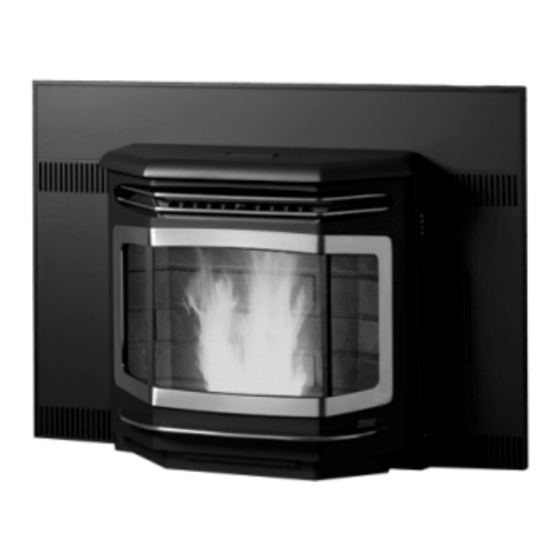
Astoria Bay Pellet Insert
- - Please read this entire manual before installation and use of this
pellet fuel-burning room heater.
could result in property damage bodily injury or even death.
- - Contact local building or fire officials about restrictions and
installation inspection requirements in your area.
- - Save these instructions
Installer: After installation give this manual to the home-
owner and explain operation of this stove.
Copyright 2007, T.I.
$10.00
Part # 100-01144
4051228
•
Masonry Fireplace
•
Factory Built (Metal)
Fireplace
•
Mobile Home Approved
Failure to follow these instructions
4800 Harbour Pointe Blvd. SW
Mukilteo, WA 98275
Tested and Listed by
Omni-Test Laboratories, Inc.
Beaverton, Oregon
Report # 028–S–51-2
ASTME-1509 1995, ULCC
1482
Advertisement
Table of Contents

Subscribe to Our Youtube Channel
Related Manuals for Avalon Astoria Bay


Summary of Contents for Avalon Astoria Bay
- Page 1 Beaverton, Oregon Report # 028–S–51-2 ASTME-1509 1995, ULCC 1482 Astoria Bay Pellet Insert - - Please read this entire manual before installation and use of this pellet fuel-burning room heater. Failure to follow these instructions could result in property damage bodily injury or even death.
-
Page 2: Introduction
Introduction Introduction We welcome you as a new owner of a Astoria Bay pellet heater. In purchasing a Astoria Bay you have joined the growing ranks of concerned individuals whose selection of an energy system reflects both a concern for the environment and aesthetics. The Astoria Bay is one of the finest home heaters the world over. -
Page 3: Table Of Contents
Table of Contents Introduction Operation (continued) Introduction ............2 Manual Mode.............19 Important Information .........2 Auto Mode ............20 Restrictor Adjustment .........21 Safety Precautions Adjusting the Fan Speed........21 Safety Precautions ..........4 Start-Up Sequence..........21 Specifications "AUGER ON" Light..........21 Heating Specifications ........6 "FAULT" Light ............22 Dimensions............6 Power Outages..........22 Electrical Specifications........6... -
Page 4: Safety Precautions
Safety Precautions • Do not operate the • Contact your local building heater if you smell officials to obtain a permit smoke coming from and information on any the heater. Turn the installation restrictions or switch to inspection requirements OWER "OFF", monitor your in your area. -
Page 5: Mobile Home
Safety Precautions • The heater will not operate • This heater must be during a power outage. If connected to a standard a power outage does 115 V., 60 Hz grounded occur, check the heater electrical outlet. Do not for smoke spillage and use an adapter plug or open a window if any sever the grounding plug. -
Page 6: Specifications
Specifications Heating Specifications: Approximate Maximum Heating Capacity (in square feet)* ........800 to 2,250 Burn Rate (Pounds per Hour)**................1.7 to 5.5 Maximum Burn Time on Low Burn** ..............28 to 52 Hours Hopper Capacity (based upon hopper extension position).........48 to 89 Pounds Heating capacity will vary depending on the home's floor plan, degree of insulation, and the outside temperature. -
Page 7: Installation
Installation Before You Begin READ THIS ENTIRE MANUAL BEFORE YOU INSTALL AND USE THIS HEATER. FAILURE TO FOLLOW THE INSTRUCTIONS MAY RESULT IN PROPERTY DAMAGE, BODILY INJURY, OR EVEN DEATH. Check with local building officials for any permits required for installation of this pellet heater and notify your insurance company before proceeding with installation. -
Page 8: Hopper Extension Set-Up
Installation Hopper Extension Set-up This pellet heater has a variable-height hopper. This allows the hopper to be lowered for smaller fireplaces. Follow the instructions below to set the correct hopper extension position. • Determine the correct hopper extension position following the directions below. The unit will extend 14”... - Page 9 Installation • Remove the correct knock-outs in the hopper walls following the directions below. If you are using hopper extension position F, remove the top knock-out. If using position E, remove the second knock-out, (etc...). The second-to-bottom knock-out is position B. Position F Knock-Out Position E Knock-Out Use a center-punch (or other suitable...
-
Page 10: Clearances
Installation Clearances • Insert must be placed so that no combustibles are within, or can swing within (e.g. drapes, doors), 36" of the front of the heater. 12” • Insert must be placed a minimum 8-3/4" from The mantel must fall a side wall (or combustible protruding more than 3/4"). -
Page 11: Venting The Pellet Stove
Installation Venting the Pellet Stove • PELLET VENT MUST MAINTAIN A MINIMUM 3" CLEARANCE TO ANY COMBUSTIBLE (INSTALL VENT AT CLEARANCES SPECIFIED BY THE VENT MANUFACTURER). • DO NOT CONNECT THE PELLET VENT TO A VENT SERVING ANY OTHER APPLIANCE OR STOVE. •... -
Page 12: Mobile Home Requirements
Installation Mobile Home Requirements • Outside air is required (used for combustion) - see the directions below. WARNING: DO NOT INSTALL IN SLEEPING ROOM. CAUTION: THE STRUCTURAL INTEGRITY OF THE MANUFACTURED HOME FLOOR, WALL, AND CEILING/ROOF MUST BE MAINTAINED. Outside Air (used for combustion) •... -
Page 13: Restrictor Adjustment
Installation Baffle Installation Install the baffles included with the insert (see page 27 for details). Restrictor Adjustment The exhaust restrictor “fine tunes” your appliance, ensuring it pulls the correct amount of air through the firebox. Altitude, vent configuration, and other factors make restrictor adjustment necessary for every installation. -
Page 14: Surround Panel & Circuit Board Installation
Installation Surround Panel & Circuit Board Installation N O T E : Attach the vent prior to installing the surround panels (& circuit board). Attach the surround panels to the insert by sliding the slots on each panel over the tabs on the side of the insert. Slot NOTE: When in place, the panels maintain a 3/8”... -
Page 15: Installation Into A Masonry Fireplace
Installation Installation into a Masonry Fireplace Vertical Cap “L” Vent Cover Plate (non-combustible) Storm Collar Seal the cover plate with silicone. “L” Vent Flex Section HINT: Paint the interior of the fireplace with latex paint to prevent fireplace odors from entering the home. Outside air may be drawn from the ash cleanout. -
Page 16: Installation Into A Factory Built (Metal) Fireplace
Installation Installation into a Factory Built (Metal) Fireplace “L” Vent Vertical Cap Cover Plate (non-combustible) Storm Collar Seal the cover plate with silicone. The log grate, screen (and rails), “L” Vent Flex Section and doors (if present) must be removed. The smoke shelf, shields, damper, and baffles may be removed if attached... -
Page 17: Operation
Operation Safety Notice • Read this entire manual (especially the "Safety Precautions" on pages 4 and 5) before using this heater. Failure to follow the instructions may result in property damage, bodily injury, or even death. • Do not unplug the heater to turn it off. This heater relies upon electricity to push the flue gases out the pellet vent –... -
Page 18: Loading Pellets
Operation Loading Pellets Lift the hopper lid to its vertical position. Pour pellets into the hopper until full. NOTE: The hopper holds approximately 48 to 88 pounds of pellets (depending upon hopper set-up). The front edge of the hopper lid becomes very hot, do not touch the area below... -
Page 19: Manual Mode
Operation Manual Mode Manual mode requires the user to turn the AUTO heater on and off manually. MANUAL To Start MANUAL DOWN Press the "Manual Start" button. That's it. The stove automatically goes to a medium burn rate START and high fan while the igniter starts the fire burning within 10 minutes. -
Page 20: Auto Mode
Operation Auto Mode Auto mode allows you to use a thermostat to control room temperature. The stove automatically turns on when the temperature drops below the thermostat setting. Once the stove reaches operating temperature, the stove then runs at the heat output setting selected. To Adjust Room Temperature (or Start the Stove) Move the thermostat to the heat setting desired. -
Page 21: Restrictor Adjustment
Operation Restrictor Adjustment The exhaust restrictor “fine tunes” your appliance, adjusting the amount of air flowing to the flame. NOTE : the optimal restrictor position will vary over time as soot builds up inside the exhaust system. Not Enough Air: If clinkers develop or the flame appears lazy and slow to blow the ash out of the firepot, pull the... -
Page 22: Start-Up Sequence
Operation Start-Up Sequence This stove utilizes a start-up sequence whenever the mode switch is changed or the heater is started when cold. This is to ensure proper operation through all possible settings and operational states (hot or cold, pellets burning or not burning, etc.). This sequence over-rides all user settings (except the "OFF"... -
Page 23: Maintenance
Maintenance Daily Maintenance (whenever using the heater) Inspect the Burn When burning on high, the flames should be bright orange with embers jumping from the firepot. NOTE : the optimal restrictor position will vary over time as soot builds up inside the exhaust system. -
Page 24: Check Firepot For Clinkers
Maintenance Daily Maintenance (whenever using the heater) - Continued Check Firepot for Clinkers If the flames seem to be coming only from the sides, or are orange/black, turn the heater off and check for clinkers. The most likely causes are: •... -
Page 25: Bi-Weekly Maintenance (Or Every 10 Bags Pellets)
Maintenance Bi-Weekly Maintenance (or every 10 bags of pellets) Clean the Heat Exchange Tubes WARNING: With the door closed, insert the included The front of the tool into the hole on the heat exchanger heater becomes very cleaning rod. Move the heat exchange hot during operation. -
Page 26: Opening The Door
Maintenance Bi-Weekly Maintenance (or every 10 bags of pellets) - Continued Opening The Door Phillips Screwdriver Bracket (attached to side of Swing open this panel to heater) access the door latch (use the tool if necessary). Pawl Door Frame Lock Nut When securing the door, make sure the pawl fits over the bracket before tightening. -
Page 27: Check Ashbox And Ashpan, Dispose
Maintenance Bi-Weekly Maintenance (or every 10 bags of pellets) - Continued Check Baffles, Ashbox, Ashpan, Dispose Ash If Necessary NOTE: The left baffle is larger than the right baffle. BAFFLE INSTALLATION WARNING: The firebox baffles install on ledges at the top of The front of the heater the firebox. -
Page 28: Sweep Ash Into Ashpan
Maintenance Bi-Weekly Maintenance (or every 10 bags of pellets) - Continued Sweep Ash Into Ashpan HINT: The more often you clean out the flyash, the more efficient your heater will burn. NOTE: Remove the ashbox prior to conducting the service below. WARNING: The firebox becomes very hot during operation. -
Page 29: Yearly Maintenance (Or Every Two Tons)
Maintenance Yearly Maintenance (or every two tons) WARNING: Disconnect the power cord prior to conducting service. The following section details extensive maintenance procedures. We strongly suggest these items be carried out by a trained service technician, possibly by a service agreement set up with your dealer. Soot and Flyash: Formation and Need for Removal –... -
Page 30: Clean The Exhaust Blower
Maintenance Yearly Maintenance (or every two tons) - Continued Clean the Exhaust Blower (make sure the heater is cool and unplugged) Remove the six screws holding the exhaust blower motor in place. Remove the surround panels and access the left side of the heater. Remove the shroud covering the blower motor. -
Page 31: Door Seal
Maintenance Yearly Maintenance (or every two tons) - Continued Door Seal Air leaks into the firebox will decrease the stove's performance greatly, leading to excessive sooting, inefficient burning, and perhaps a malfunction. • The door gasket must contact the entire perimeter of the door and create an air- tight seal. -
Page 32: Adjusting The Door Hinge And Latch
Maintenance Adjusting the Door Hinge and Latch • The door hinge and door latches may be adjusted to pull the door closer to the body. The illustration below details how to adjust these components. NOTE: Make sure to read the section "Door Alignment"... -
Page 33: Check For Air Leaks - Door, Glass And Ashpan
Maintenance Check for Air Leaks Around the Door, Glass, and Ashpan Air leaks into the firebox will decrease the stove's performance greatly, leading to excessive sooting, inefficient burning, and perhaps a malfunction. • Inspect the door gasket to make sure it is fully attached. Use stove gasket cement to re-attach if necessary. -
Page 34: Normal Operating Sounds
Normal Operating Sounds Auger Motor When feeding pellets, you Exhaust Blower may hear the intermittent The blower may buzz of this motor running. create a low-pitched hum. This sound will change as the FEED RATE is altered. Heat Exchanger Tubes You may hear the heated air being forced through these tubes by the... -
Page 35: Safety Label
For use in masonry or factory built (ZC) fireplaces. Travis Industries, Inc. 10850 117th Pl. NE Pellet Serial No. Kirkland, WA 98033 Insert Model: Astoria Bay PI Electrical Rating: 115 V., 60 Hz., (Avanti PI) HEARTH EXTENSION Report No.: 028-S-51-2 Start 3 Amps, Tested to: ASTM E1509-95 Run 1.5 Amps... -
Page 36: Warranty
Limited 7 Year Warranty To register your TRAVIS INDUSTRIES, INC. 7 Year Warranty, complete the enclosed warranty card and mail it within ten (10) days of the appliance purchase date to: TRAVIS INDUSTRIES, INC., 4800 Harbour Pointe Blvd. SW, Mukilteo, WA 98275. TRAVIS INDUSTRIES, INC. warrants this gas appliance (appliance is defined as the equipment manufactured by Travis Industries, Inc.) to be defect-free in material and workmanship to the original purchaser from the date of purchase as follows: Check with your dealer in advance for any costs to you when arranging a warranty call. -
Page 37: Optional Equipment
Optional Equipment Thermostat (Part # 99300650) Do not connect 120 VAC to the thermostat circuit of this heater (do not use a household thermostat used for a wall-board or other electical heater). Attach the thermostat wire to the circuit board (see the Attach the quick-connects illustration to the right). -
Page 38: Remote Thermostat
Optional Equipment Remote Thermostat (Part # 99300653) • Follow the instructions included with the remote thermostat for installation and operation. Optional Log (Part # 98900126) Make sure the heater has fully Left Log Shelf Leg cooled before installation. Open the door (see the instructions Right Log Shelf Leg included with the owner’s manual. -
Page 39: Zc Kit
Optional Equipment ZC Kit (99200149) The optional zc kit allows this insert to be directly into the framing of a house or mobile home. See the kit for installation details. Floor Protection Rear Vent Shield (used only on inserts Vent Clearances (make sure venting directly to the rear - note how it is all vent maintains 3”... -
Page 40: Index
Index Adjusting the Fan Speed........21 Gold (cleaning)..........25 Air Leaks............33 Hearth Requirements.......... 10 Ashpan (Opening and Disposing Ashes) ....27 Heat Exchange Tubes (cleaning) ......25 AUGER ON Light..........21 Heating Specifications........6 Auto Mode ............20 Hopper Cleaning (Vacuum Hopper) ......25 Bi-Weekly Maintenance (or every 10 bags pellets) ..25 Important Information .........
Need help?
Do you have a question about the Astoria Bay and is the answer not in the manual?
Questions and answers