Table of Contents
Advertisement
Quick Links
Advertisement
Table of Contents

Related Manuals for TracVision R1DX


Summary of Contents for TracVision R1DX
- Page 1 TracVision ® with Multi-service Interface Box/Controller...
-
Page 2: Table Of Contents
(Mon.-Fri., 9 am-6 pm ET; Sat. 9 am-2 pm ET) KVH, TracVision, and the unique light-colored dome with dark contrasting baseplate are registered trademarks of KVH Industries, Inc. All other trademarks are property of their respective companies. The information in this document is subject to change without notice. -
Page 3: Inspect Parts And Get Tools
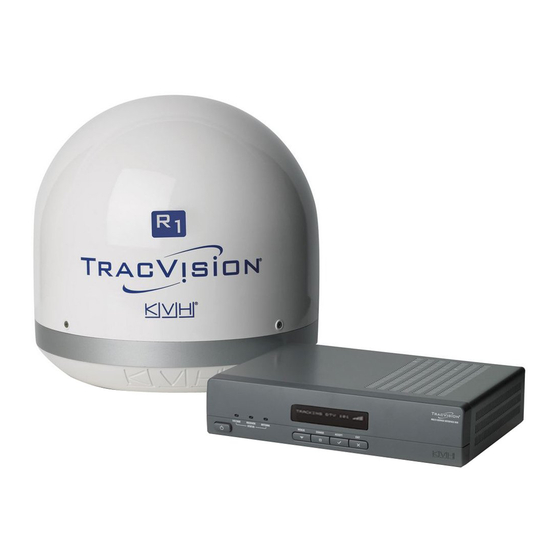
Inspect Parts and Get Tools Before you begin, follow these steps to make sure Figure 1: TracVision R1DX System Components you have everything you need to complete the Antenna installation. IMPORTANT! Always lift the antenna by the baseplate and never by the radome or any portion of the internal antenna assembly (see Figure 1). -
Page 4: Plan The Installation
Plan the Installation Before you begin, consider the following Figure 3: Blockage from Obstruction installation guidelines: • Minimize blockage. The antenna requires a clear view of the southern sky to receive satellite TV. Using the guidelines in Figure 3 Obstruction Antenna as a guide, mount the antenna a suitable distance away from obstructions on the roof,... -
Page 5: Prepare The Antenna
Prepare the Antenna Follow these steps to attach the four mounting Figure 5: Attaching the Mounting Plates plates to the antenna’s baseplate. a. Attach the four supplied metal mounting plates to the bottom of the antenna using the eight M5 screws supplied in the kitpack (see Figure 5). -
Page 6: Wire The Antenna
Wire the Antenna Follow these steps to connect the antenna cable to Figure 6: Connecting the Antenna Cable the antenna. a. At the location you chose in Step 2 on page 4, use a 5/8" hole saw to cut out a cable access hole in the vehicle’s roof. -
Page 7: Mount The Antenna
Mount the Antenna Follow these steps to mount the antenna to the Figure 8: Mounting the Antenna roof. Front of Vehicle a. Apply appropriate construction adhesive to the bottom of the antenna’s four mounting Vehicle plates across all of the holes. Centerline Ø0.19"... -
Page 8: Wire The Interface Box
Wire the Interface Box Follow these steps to connect the antenna cable Figure 9: Wiring the Interface Box and receiver(s) to the interface box. IMPORTANT! Terminate all RF coaxial cables, including the Antenna ® antenna cable, with Snap-N-Seal F-connectors using an Augat IT1000 tool. Low-quality connectors will degrade system Roof performance and KVH’s warranty does not... -
Page 9: Connect Power
Connect Power The interface box requires 10-16 VDC power Figure 12: Interface Box Power Wiring input supporting 50 watts (4.2 amps @ 12 VDC). Black Follow these steps to connect power to the Ground interface box. Input Power CAUTION (10-16 VDC) For your own safety, shut down vehicle power before you connect the wires. -
Page 10: Mount The Interface Box
Mount the Interface Box Once all cables are connected, follow these steps Figure 13: Interface Box Mounting to install the interface box inside the vehicle. a. Attach the two mounting brackets to the sides of the unit using three #2-56 screws. Simply screw these fasteners into the vent 1⁄4"... -
Page 11: Turn On The System
TRACKING DTV 101 panel (see Figure 16), follow the steps in the SYSTEM NEEDS SETUP next section to set up the TracVision system for the customer’s service provider: Option 1 - DISH Network (see page 12) Option 2 - DIRECTV (see page 13) -
Page 12: Set Up The System
Set Up the System Option 1 - DISH Network Follow these steps and refer to the flowchart in Figure 17 to set up the system for DISH Network. Figure 17: DISH Network Setup a. Press any button on the interface box front TRACKING DTV 101 Press any button panel. - Page 13 Set Up the System Option 2 - DIRECTV Follow these steps and refer to the flowchart in Figure 19 to set up the system for DIRECTV. Figure 19: DIRECTV Setup a. Press any button on the interface box front Press any button TRACKING DTV 101 panel.
-
Page 14: Enter Latitude & Longitude
Enter Latitude & Longitude Follow these steps and refer to the flowchart in Figure 20: Latitude/Longitude Setting Figure 20 to enter your vehicle’s latitude and Press MENUS until LAT/LONG is displayed. longitude into the system. The antenna will use your position information to speed up satellite LAT/LONG= 41N, 071W acquisition, which is critical for DISH Network NEXT MENU... -
Page 15: Run Check Switch Tests
Run Check Switch Tests DISH Network Only If you set up the system for DISH Network, follow these steps to run the receiver’s Check Figure 22: Expected Check Switch Results Switch test as required. DISH 1000/129 Results Primary Receiver - 2 Check Switch Tests Port Follow these steps to run two Check Switch tests on the primary receiver, which is connected to... - Page 16 Continued Run Check Switch Tests DISH Network Only Resetting the System Before Retrying If the receiver Check Switch results displayed on Figure 23: Factory Reset the TV do not match the expected values shown Press MENUS until in Figure 22 on page 15, follow these steps and DIAGNOSTICS= No is displayed.
-
Page 17: Educate The Customer
TV. Common causes of blockage include trees, buildings, bridges, overpasses, and mountains (see Figure 25). The TracVision system will not work inside a garage. Heavy rain or snow might also temporarily interrupt reception. • Clean the antenna regularly. Dirt buildup on the radome can affect satellite TV reception. - Page 18 www.kvh.com KVH Industries, Inc. KVH Singapore KVH Europe A/S KVH Norway AS World Headquarters EMEA Headquarters Asian Headquarters Horten, Norway Middletown, RI U.S.A. Kokkedal, Denmark Singapore Tel: +47 33 03 05 30 Fax: +47 33 03 05 31 Tel: +1 401 847 3327 Fax: +1 401 849 0045 Tel: +45 45 160 180 Fax: +45 45 160 181 Tel: +65 6513 0290 Fax: +65 6472 3469 E-mail: info@no.kvh.com...
Need help?
Do you have a question about the R1DX and is the answer not in the manual?
Questions and answers