
Related Manuals for Genway WL-03NL


Summary of Contents for Genway WL-03NL
- Page 1 WL/CM-03NL(E crust) Network video doorphone system Please don't abandon the products as wastes at will. It should be recycled and disposed separately. Thanks! (Edition:V1.00)
- Page 2 Instructions for relay equipment wiring ¡ VM-03N video amplifier Connect VCC,GND terminal with DC12V power's positive and negative polarity respectively (2)VFO,GND is one video output, connect with network equipment's TV+, TV- respectively (3)VF1~VF3, GNDare three video outputs, connect VF1~VF3 terminal with network equipment's TV+, and connect GND terminal with network equipment's TV- (4)VCOM,AUDIO+are three audio ports, it is convenient for user only, you can connect audio wire with VM-03N, also you can select not connect audio wire...
-
Page 3: Table Of Contents
14¡Supplemental manual for network relay equipment(attachments) Contents ¡¡¡¡¡¡¡¡¡¡¡¡¡¡¡¡¡¡¡¡¡1 1¡ System introduction Attached supplemental manual for network video door phone's relay equipments 2 System Characteristics ¡ ¡¡¡¡¡¡¡¡¡¡¡¡¡¡¡¡¡¡¡ ? 3¡ System constitution ¡¡¡¡¡¡¡¡¡¡¡¡¡¡¡¡¡¡¡¡¡1 Relay equipment features 4¡Product structure and functions¡¡¡¡¡¡¡¡¡¡¡¡¡¡¡¡ ¡ VM-03N video amplifier: amplifies the video signal for long distances 5¡System components and parameters¡¡¡¡¡¡¡¡¡¡¡¡¡¡... -
Page 4: System Introduction
(8)Wall phone£CM-03NWD(A)(Optional) damaged or not it represent the card isn't registered or canceled record or damaged. ¡ System combination for audio system: (1)Door station£WL-03NL¡WL-03NL-C¡WL-03NLA¡WL-03NLA-C (2)Indoor phone£ WL-02NLFD¡WL-02NLFH¡WL-02NLFC¡WL-02NLFH1¡WL-02NLFL (3)Module£WL-03NLCH (4)Power£2-PSE¡PS-5E¡PS-9... -
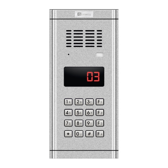
Page 5: Product Structure And Functions
¢ Small cover ¨ Door Station ¢ WL-03NL CM-03NL CM-03NLA Installation steps on iron door: (1)Drill a rectangular hole on proper position of the iron according to door station installation size. (2)Pull out the two small covers. Take off the screws with the attached inner hexagon wrench, and then take off the door station back cover. - Page 6 ¨ Indoor Phone (5)Module£ CM-02NLRG CM-02NLRH Model Size Installation diagram£ 86¡86¡mm45 WL-03NLCH MONITOR CM-03NLCH 146¡86¡mm45 CALL UNLOCK (6)Module and Network switch£ BUSY POWER Model Size Installation diagram£ (1) ¡ ¡ mm ?62-NLCH03-CM 62 110 45 Display screen Unlock Volume Handset ¡...
- Page 7 (3)Installation size and diagram of indoor phones£ Indoor Phone ¨ Model Size Installation diagram£ CM-02NLRI CM-02NLRJ 112mm ¡ ¡ CM-02NLRG 205 220 65.5 Í» BUSY ÕÏ POWER µÔ ¡ ¡ mm 224 218 59 CM-02NLRH CM-02NLRG Holder CM-02NLRH Holder Model Size TALK Installation size£...
-
Page 8: System Components And Parameters
Installation size on iron door Installation size on wall f)Humidity:45%¡95% (1)Installation size table for aluminum alloy door station series£ Door station Installation size on Installation size Cover length Model WL-03NL Audio Door Station L(mm) size(mm) iron door (mm) on wall(mm) ¡?? 304¡? NL03-WL 296)?L(¡???)?W(¡??)?D( 2?4)2L(¡?26)2W(¡42)2D(... - Page 9 ¢Pick up the handset of the ringing phone, you can talk with the calling indoor phone about 120sec. CM-02NLRG/CM-02NLRG-C Indoor Phone you can also talk with the door station (during this time, you can hear the¡busy line¡indication). When the calling indoor phone hangs up, the called indoor phone can talk with the door station. a)Working Voltage:18V DC¡10% ¢If the system connects with a front door station, the operation is the same with the door b)Standby Current:¡15mA...
- Page 10 Door station call indoor phone in the same building: press * and input the room ¡ ¡ C Main Indoor Phone-NLRaM02-CM/NLRaM02-CM No. that's all. For example: If you want to call NO. 102 family, when room number is ¡ ¡ three digits: press Room No.
- Page 11 Monitor function: press the Monitor button in the indoor phone, you can see the ¡ ¡ Free Indoor Phone-NLRJ Hands02-CM condition outside door for 15 seconds. If you want to cancel the monitor, just press the ¡ Monitor button again. (Note: If somebody calls another indoor phone at this time, ¡...
- Page 12 3.How to adjust the tones£Uncover the door station.) (£ CM-03NZH Conformity Unit(4 route way tone with the four holes. a)Working Voltage: V DC?2¡?0? V DC6¡?0? b)Standby Current:¡85mA 2 3 4 5 6 7 8 c)Working Current:¡500mA Position ?£adjuster for the d oor station speech volume position 2£adjuster for the i ndoor phone ring volume...
- Page 13 10¡System setting(video/audio system are same) Audio Indoor Phone POWER GND DATA TV+ MONI +18V +18V MONI DATA POWER a)Working Voltage:DC12V¡10% COM SET Port3 Port4 A+18V AFOUT DATA AGND MONI V+18V VGND TVOUT T&R MONI AGND V+18V VGND TV A+18V GND T&R MONI AGNDV+18V VGND TV A+18V...
-
Page 14: System Diagram
6¡System diagram 9¡Wiring Material £ Non-Network system diagram Diagram Wire material requirements(vertical square) Remarks (1)Non-Network video system diagram£ ¡30M ¡100M Between door station and RVV6¡0.75mm RVV6¡1.5mm module SYV75-5/96 PCS¡ SYV75-5/96 PCS¡ ¡30M ¡100M Between Hand-set CM-02NLRV or indoor module CM-02NLRV-C phone RVV4¡0.5mm +SYV75-5/96 RVV4¡1.5mm +SYV75-5/96... -
Page 15: Non-Network Audio System Diagram
(2)Wiring between switches and among switch, door station, module, and conformity unit: (2)Non-Network audio system diagram£ ¢Wiring among switches: Common Audio input Audio GND Audio input Audio GND WL-02NLFC Data A Data B Network for No.1 input for No.1 for No.2 input for No.2 terminal route way... -
Page 16: Network System Diagram
¢Wiring among network switches: Network system diagram Common Audio input Audio GND Video input Video GND (1)Network v ideo system diagram£ Network Data A Data B CM-02NLRM or terminal for No.1 input for No.1 for No.1 input for No.1 CM-02NLRG or route way route way route way... -
Page 17: Network Audio System Diagram
¢ Wiring instruction from module to i ndoor phone CM-02NLRV/CM-02NLRI/CM-02NLRJ£ (2)Network audio system diagram£ WL-02NLFD Audio Video Video Audio Audio WL-02NLFH Audio Monitor Video WL-02NLFL WL-02NLFH1 WL-02NLFC cortrol GND Power Power Module V+18V VGND T&R MONI AGND A+18V Video Video Audio Audio Audio... -
Page 18: Diagram For Main Indoor Phone Cm-02Nlram
8 Wiring Instruction ¡ 3.Diagram for main indoor phone CM-02NLRaM£ WL-06NFbH CM-02NLRbM CM-02NLRbM ?.Wiring Instruction for video system Extra Indoor Phone Extra Indoor Phone Extra Indoor Phone (1)Wiring Instruction among door station, power and lock: Audio Audio GND Electrical Electrical Door power power... -
Page 19: System Wiring
¢Wiring between module and indoor phone£ 7¡System Wiring 1.Non network wiring for video system: +12V (1)Video system-1(module CM-03NLCH-162)£ GND+12V AGND T&R AGND VGND V+18V MONI T&R AGND A+18V T&R A+18V AFOUT DATA AGND MONI V+18V VGND TVOUT T&R MONI AGND V+18V VGND TV A+18V GND T&R MONI AGNDV+18V VGND TV... - Page 20 (2)Video system-2(module CM-03NLCH-162)£ b)Wiring among WL -03NQH switch, WL -03NLCH module and door station: Connect with Door Station door bell button PS-2E Power VGND V+18V Only for ¡AC¡ ¡AC¡ AGND TRANSFORMER CM-02NLRM1 MONI WL-03NLCH Module Model£ PS-2E Input£230V 50¡60Hz Output£13.5V 800mA T&R Notes:Used in indoor...
- Page 21 (3)Video system-3(module CM-03NLCH)£ ¢Wiring among switch , module and door station: a)Wiring among WL -03NQH2-162 switch, WL -03NLCH-162 module and door station: PS-2E Power Door Station T&R MONI ¡AC¡ ¡AC¡ AGND TRANSFORMER Model£ PS-2E V+18V Input£230V 50¡60Hz Output£13.5V 800mA VGND Notes:Used in indoor TVOUT +DC-...
-
Page 22: Non-Network Wiring For Audio System
2.Non network wiring for audio system£ Wiring between conformity unit and WL -03NQH switch (2 route ways): WL-02NLFC WL-03NQH Network Switch To Module To Door Station Note: POWER GND DATA DATA POWER (AF1+,AF1-)¡(AF2+,AF2-)¡(AF3+,AF3-)¡ (AF4+,AF4-) in the BUS board of conformity unit are connected to (AI1+,AI1-)¡(AI2+,AI2-)¡... -
Page 23: Network System Wiring
£ Network system wiring (2)Network wiring for audio system ¢ Wiring between conformity unit and switch: (1)Network wiring for video system Wiring between conformity unit and CM-03NQH2-162 switch (2 route ways): ¢ Wiring between conformity unit and switch: To Extra CM-03NQH2-162 Wiring between conformity unit and switch (2 route ways):... - Page 24 Wiring between CM-03NLCH module and CM-02NLRaM main indoor phone£ b)Wiring between conformity unit and NQH03-CM switch (4 route ways): CM-06-03NLd CM-03NLCH Module Front door station CM-03NQH Network Switch Note: POWER GND DATA TV+ MONI +18V +18V MONI DATA POWER (AF1+,AF1-)¡(AF2+,AF2-)¡(AF3+,AF3-)¡ (AF4+,AF4-) in the BUS board of conformity To Module To door station...
-
Page 25: Wiring Among Switch, Door Station And Module
¢ Wiring among switch , module and door station: Wiring between CM-03NLCH-162module and CM-02NLRaM main indoor phone£ CM-06-03NLd Wiring among CM -03NQH2-162 switch, CM -03NLCH-162 module and door station: Front Door Station Door Station with card reader CM-03NLCH-162 Module CM-03NLCH-162 Module PS-5E Power A+18V AFOUT DATA AGND MONI V+18V VGND TVOUT T&R MONI AGND V+18V VGND TV... - Page 26 b)Wiring among CM-03NQH switch,CM-03NLCH module and door station£ c)Wiring between CM-03NLCH module and indoor phone£ Door Station CM-03NLCH Module PS-5E Power AGND VGND ¡AC¡ V+18V TVOUT TRANSFORMER TVIN Model£ PS-5E Input£230V¡50Hz Output£18V 800mA VGND MONI Notes:Used in indoor T&R V+18V +DC- MONI A+18V...
- Page 27 b)Wiring between CM-03NLCH-162 module and indoor phone£ c)Wiring among CM-03NQH switch,CM-03NLCH-162 module and door station£ Door Station CM-03NLCH-162 Module PS-5E A+18V AFOUT DATA AGND MONI V+18V VGND TVOUT T&R MONI AGND V+18V VGND TV A+18V GND T&R MONI AGNDV+18V VGND TV A+18V ¡AC¡...
- Page 28 d)Wiring among CM-03NQH2-162 switch,CM-03NLCH module and door station£ ¢ £ Wiring between module and indoor phone Door Station PS-5E Power Wiring between CM-03NLCH-162 module and indoor phone£ ¡AC¡ CM-03NLCH Module TRANSFORMER AGND Model£ PS-5E Input£230V¡50Hz Output£18V 800mA VGND Notes:Used in indoor V+18V TVOUT +DC-...