Table of Contents
Advertisement
Quick Links
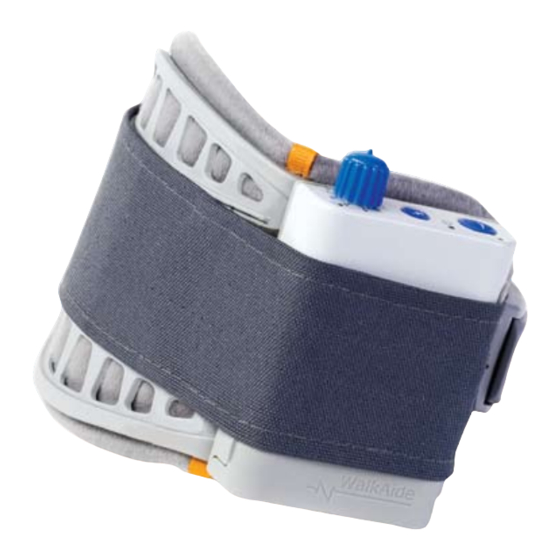
The WalkAide
System
®
Clinician Manual
INDEPENDENCE
one step at a time
© 2010 Innovative Neurotronics. All rights reserved. All trademarks and registered trademarks
are the property of their respective holders. No part of this manual may be reproduced in any form
without the written consent of Innovative Neurotronics Incorporated. Information in this manual is
LM06-2 10/10
for the use of qualified clinicians only.
Caution: USA Federal Law restricts this device to sale by or on the order of a physician.
Advertisement
Table of Contents
Troubleshooting

Subscribe to Our Youtube Channel
Related Manuals for Innovative Neutronics WalkAide

Summary of Contents for Innovative Neutronics WalkAide
- Page 1 The WalkAide System ® Clinician Manual INDEPENDENCE one step at a time © 2010 Innovative Neurotronics. All rights reserved. All trademarks and registered trademarks are the property of their respective holders. No part of this manual may be reproduced in any form without the written consent of Innovative Neurotronics Incorporated.
-
Page 2: Table Of Contents
Wearing Schedule Timperley, Cheshire WA15 7SN Usage Log United Kingdom Tel: 0161 980 4310 Use and Care of the WalkAide and Accessories Email: info@mdqa.co.uk Care and Use of WalkAide Electrodes Additional Information Troubleshooting WalkAide Control Unit Troubleshooting The ABC’s of Electrode Placement... -
Page 3: Introduction
(Figure 2-3). The clinician uses the WalkAnalyst software on a laptop computer to program the Tilt Sensor in the WalkAide. Use of the Tilt Sensor to trigger stimulation eliminates the need for additional components and external wires from a Heel Sensor during regular use. -
Page 4: Indications Of Use
Supervision—FES should only be used under the medical supervision of a physician and a qualified clinician. The Innovative Neurotronics WalkAide System is intended to address foot drop for people who have sustained damage to upper motor neurons in the brain or the spinal cord. During the swing phase Two-Way Radios—Care should be taken while using FES therapy in close proximity (e.g. -
Page 5: Precautions
ALWAYS handle the unit carefully…do not expose the unit to water, excessive heat or vibration. use the WalkAide if it appears to be malfunctioning. If there is a change in the way it usually works (i.e. DO NOT place electrodes anywhere other than on one leg below the knee. -
Page 6: Glossary
Cuff Pretibial shell that attaches to the leg and is used to hold Tilt sensor. the electrodes and the WalkAide control module in the correct position. Modified Parameters Walking parameters that are associated with or derived... - Page 7 Walking Data Determine the timing of the initiation and termination of Retrieve WalkAide Log Allows clinician to download most current Usage Log, up to Thresholds the stimulation for either the Heel or Tilt sensors. 72 days of “Hours Per Day” and “Stims Per Day” information.
-
Page 8: Equipment
Electrodes (pkg. of 4) and WalkAide User Manual. An appropriately sized WalkAide Cuff is ordered separately and the full-length Foot Sensor is an optional item. (Figure 3) The WalkAide requires a single AA battery. Only AA alkaline (1.5 V) batteries should be used and extra batteries should always... -
Page 9: Demo Kit
The Clinician Demo Kit consists of the same equipment found in the Patient Kit. However, the serial number of the WalkAide unit is listed and tracked as a demo unit. It can be used for trial walking on For proper skincare and maximum effectiveness, the electrodes should be replaced every 1 to 2 any number of patients but cannot be sold to a patient as it becomes a used medical device. -
Page 10: Walkaide Cuff Disposable Liner
2.5 WalkAide Cuff Disposable Liner The purpose of the Disposable Liner is to serve as a hygienic barrier between patient trials. Additionally, it can shorten preparation time in follow up visits. Each Disposable Liner must be cut to fit the patient’s Cuff and the electrodes placement remains on liner for return visits. -
Page 11: Symbols And Definitions
Resend the WalkAide Parameters to Indicates impulse, STIM button WalkAide. Turn OFF unit, wait 5 seconds, turn back ON. Green power light should flash and red alert gone. If red light remains on, contact the distributor. (Bad data... -
Page 12: Installation Of The Walkanalyst Program
Follow Configuration Wizard (initial pairing only) Figure 17: Front and side views of WalkLink unit The WalkAide device sends real time data to and receives parameter changes from the WalkAnalyst program. In order to avoid connecting a physical cable to the patient, a wireless solution has been created employing Bluetooth radio technology. - Page 13 Turn on the WalkLink and open the WalkAnalyst software program. The blue light on the front of the WalkLink should begin to blink. The WalkAide can be attached to the WalkLink at any time. The blue light in the upper left hand corner of the WalkAnalyst screen will indicate a solid connection to the WalkLink, and the green light will indicate a solid connection to the WalkAide.
- Page 14 Standard method only: Enter the WalkLink MAC Address: Make sure standard method Alternate method only: Select COM Port: Make sure alternate method option is option is detected. Much like a street address or telephone number, each WalkLink detected. The COM Port Selection field should be displayed. (Figure 25 Alt) If it is not has an address that is used to ensure communication occurs only with that particular displayed, press the “Show COM Port Selection”...
-
Page 15: Overview Of Data Collection And Programming Process
If adjustments are needed in the future, the Figure 28 outlines the process used to provide the WalkAide for a new user. Bluetooth connection is dropped, or WalkAnalyst is unable to find the WalkLink device, choose the Bluetooth icon in the upper right corner of the screen. -
Page 16: Testing With The Peripheral Nerve Stimulator
Always prepare the user for the testing procedure by providing a thorough explanation Testing with the Peripheral Nerve Stimulator of the process and always ask for continuous feedback during the procedure. There are two primary purposes of the peripheral nerve stimulator testing procedure. The first is to The user should be comfortably seated in a chair with the affected leg resting on a low stool. -
Page 17: Electrode Placements And Final Preparations For Walking
Once the twitch is discovered, of the WalkAide, running the cable to the right to fit a right leg and to the left to fit a stop sliding the peripheral nerve stimulator and start increasing the intensity level until a left leg. - Page 18 (Figure 39) Anatomical variations are common. Turn the WalkAide ON by turning the blue Intensity Knob in a clockwise direction to the 1 (on) position. An audible beep will sound and a green light will flash intermittently to indicate that the unit is on.
-
Page 19: Walkanalyst Login
Place the clinician Heel Sensor in the user’s shoe on the affected side and connect its cable to the WalkAide unit. It is best to have the patient use a firm-soled shoe and walk on a hard tile Step 2: Enter username and password floor during the initial data collection procedures. -
Page 20: Rapid Programming
Step 4: Select Programming Option You will be prompted to clear your usage log. If the WalkAide unit is brand new, • Standard Programming – Detailed programming option for advance clinicians clearing the log is recommended. This sets the timer of the WalkAide; Clears •... -
Page 21: Rapid Adjustment
Select Clear WalkAide Logs (option). Required for a New Patient Kit WalkAide. Click on Click on Advanced Parameter to adjust Stimulation Comfort and Quality (Figure 47) Clear WalkAide Log to set the internal date and time stamp. This will also set a new 72-day tracking sequence. - Page 22 Step 5: Collect WalkAide Data Collect Walking Data: (Assure the cuff and WalkAide are properly positioned and there are no dan- gling cables that might impede walking. Ask the user to stand, balance and prepare to walk). Click the ’Start’ icon ; this begins to collect a live data stream and will appear on the screen. Stand Figure 53: Save &...
- Page 23 ’Send Parameters to WalkAide’ . Since most users are programmed to use the Tilt Click the ‘Optimize Gait Program’ button. The error rate for both the Hand and Heel Sensor, the TILT MODE is highlighted in green in the message window (Figure 57).
- Page 24 Click on ‘OK’ to send the parameters. The WalkAide will emit a beep and a message window will appear stating that the parameters have been successfully sent. (Figure 58) The final walking trial in Tilt Mode should reveal an effective pattern of stimulation and produce a safe pattern of walking.
-
Page 25: Exercise Mode
The Exercise Mode may be discontinued at any point in time by simply turning the WalkAide unit off, waiting 2-3 seconds, and then turning the WalkAide unit on again. It will now be ready to run the default walking program. It is important that the user remember to always turn the WalkAide unit off and then on again after any exercise session. -
Page 26: Usage Log
Remove the cuff at regular intervals throughout the day and inspect the skin under the The log will only collect data for up to 72 days. To reset the WalkAide unit Usage log file, click on electrodes. These areas will be pink due to increased blood flow under the electrodes, but this redness should disappear quickly. - Page 27 Figure 65: Graphical view of Usage Log Tabular View, the days, hours and stimulation count are listed numerically in a table (Figure 66). Figure 66: Tabular view of Usage Log Figure 68: Collected Data Graph and Parameter Listing A report of the walking trial or Usage Log may be printed (Figure 67). Click on the ‘Print’ icon in the upper right corner of the screen.
-
Page 28: Use And Care Of The Walkaide And Accessories
(48.8 degrees Celsius) or fall below 40 degrees F (4.4 degrees Celsius). This will keep the electrodes from drying out. The WalkAide should be turned off when not in use and overnight to preserve the batteries and to allow the internal clock to function optimally. -
Page 29: Care And Use Of Walkaide Electrodes
To obtain the most use from the electrodes, the following tips should be discussed and reviewed with the WalkAide user. It is a good idea to retrieve and save the parameters and usage log from the WalkAide unit each time the user returns for follow-up. This allows the parameters to be easily restored if Before applying the WalkAide system, the skin must be clean, dry and free from lotions or oils. -
Page 30: Troubleshooting
WalkAide unit. Knob by turning counter-clockwise to 0. Wait 5 seconds and then turn ON again to see if the green light is flashing. If the red light remains lit, the WalkAide unit must be Possibilities: returned to Innovative Neurotronics for repair or replacement. -
Page 31: The Abc's Of Electrode Placement
ONLY use the manual adjustment feature if the gait pattern of stimulation is NOT completely stimulation is for the user precise positioning of the electrodes lessens the sensory satisfactory after applying the Zoom in to Select Steps, Autoset WalkAide Parameters and response to the stimulation. The more precise the electrode placement, the stronger Optimize Gait Program options. - Page 32 The numerical values listed as the On and Off thresholds relate to the range of tilt (angle or heel line) available for measurement within the WalkAide unit itself. The numerical values are not a report of hip, knee or ankle alignment angles. The clinical significance of the numerical values is that a change in the numerical value of the threshold by a value of three is approximately one degree of tilt.
- Page 33 Figure 75: Lower the Wait Time allows for increases in walking speeds Figure 74: The Min and Max Times have been set too low, providing only a brief period of stimulation. In general, the Min, Max and Wait Time values will be higher for slower walkers as they spend more time in swing and more time in stance.
- Page 34 Control Times – The Min Time, Max Time and Wait Time are best adjusted on the Graphs screen by moving the appropriate sliders to produce a consistent pattern of stimulation. The values of these Times are automatically transferred to the Modified Parameters.
- Page 35 The Tilt Mode is the preferred stimulation mode for most users. The tilt function For example, when testing the WalkAide system on a user with a smaller leg or operates by tracking the movement and speed of the lower leg during walking. An a child, the Pulse Width should be lowered to 25 prior to testing the system.
- Page 36 If this is the case, the Filter Setting can be increased and new data collected. WalkAide Serial Number – For reference, the WalkAide unit serial number will be This will smooth the appearance of the graphs in any new data collected but will automatically logged and noted.
-
Page 37: Anatomy Of Tilt And Heel Data
Anatomy of Tilt and Heel Data Follow-Up and Re-Optimization The WalkAide system is designed to be part of a progressive rehabilitation program. Notably, many users increase walking speed over time with consistent use of functional electrical stimulation. Other changes in the walking pattern include decreased effort with gait, changes in step and stride length, improved symmetry of stance and swing phases, decreased need for external support (i.e. - Page 38 Connect all equipment (including the Heel Sensor) and establish Bluetooth connection. connection. Click on ‘Save WalkAide Settings’ and then click on the icon labeled ‘Save Click on ‘Save WalkAide Settings’ and then click on the icon labeled ‘Save WalkAide Settings’.
-
Page 39: Walklink And Bluetooth Troubleshooting
WalkLink and Bluetooth Troubleshooting Problem 2 : The WalkLink device did not appear during the WalkAnalyst Bluetooth configuration process Section 1: Hardware: Bluetooth USB Device Problem 1: Conflict with internal Bluetooth or another Bluetooth driver installed on the Turn the WalkLink off for ten seconds, turn it back on and press search again. computer Confirm that the laptop is using Windows XP Service Pack 2 or better, Windows 7 or Vista. -
Page 40: Walkaide User Manual
Bluetooth connection must be reestablished. Information regarding air travel with the WalkAide is also provided in the User Manual along with a WalkAide Medical Device ID card (Figure 86). The Transportation Security Administration (TSA) -
Page 41: Technical Information
Electrodes (Short Term - less than 1 month) Austin, TX 78746 Temperature: 32° – 104° F (0° – +40° C) Toll Free (888) 884-6462 Humidity: 35 – 50% Local (512) 721-1900 www.walkaide.com / support@ininc.us Clinical Support Operations Center Customer Support Technical Support 888-884-6462 888-884-6462...
Need help?
Do you have a question about the WalkAide and is the answer not in the manual?
Questions and answers