
Related Manuals for Totalcomp TCM2 Series


Summary of Contents for Totalcomp TCM2 Series
-
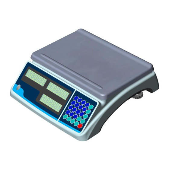
Page 1: Counting Scale
TCM2 Series Counting Scale Operation Manual V1.0 Contents Subject to Change without Notice... -
Page 2: Table Of Contents
CONTENT 1. Specification ..................3 2. Housing ....................4 3. Faceplate ....................4 4. Keys function Summary ..............6 5. Weighing Operation ................7 6. Calibration ..................11 7. LCD contrast and Backlight mode setting ........12 8. Auto-off time setting ................12 9. -
Page 3: Specification
TCM2 Counting Scale Instruction Manual Thank you for purchasing Model TCM2 Counting Scale. Please read all operating instructions carefully before using and note the following points: Avoid using in extreme heat, cold or wet and the environment which has intensive change in temperature, humidity and pressure. -
Page 4: Housing
2. Housing Interface: (2) load cell connector DB9 Male (3) Rocker switch (4) AC power adapter input (5) RS232 connector DB9 Female 3. Faceplate 3.1 Front Display Panel:... - Page 5 3.2 Key Pad 3.3 Symbol Meaning: 3.3.1 WEIGHT: Weight window. 3.3.2 PIECE WEIGHT:Piece weight window. 3.3.3 COUNT:Count window. 3.3.4 ZERO:Zero indicator. 3.3.5 TARE:Tare indicator. 3.3.6 Kg/Lb:Weight unit indicator. 3.3.7 Kg/Lb: Piece weight indicator. 3.3.8 PRINT:Data output indicator. 3.3.9 1/2:1: Main platform is used; 2: Remote platform is used. 3.3.10 CHG:Battery charging indicator.
-
Page 6: Keys Function Summary
4. Keys function Summary 0~9: numeric keys:Enter numerical data. CLEAR: Clear the input data and accumulated pieces. EXIT: When scale is not in normal weighing mode, EXIT key is used to exit and back to normal weighing mode. ENTER: Confirm the operation or save the data. ZERO: Set the zero point when scale is stable, zero range: power-on zero point ±5%FS. -
Page 7: Weighing Operation
5. Weighing Operation 5.1 Turn the power on and off 5.1.1 When the scale is off, press “ON/OFF” key to power on the scale. The self-test will run and the scale will give the zero reading. Now it is ready for weighing. 5.1.2 When the scale is beyond the zero point range after powering on (Calibration zero point±15%FS), the scale displays “Err04”or“Err05”. - Page 8 5.6 Print 5.6.1 Under the normal weighing mode, when the scale reading is stable, press “PRINT” key to output the data via RS232 interface as following format. 5.6.2 Print Out format (ref. to 10.8, the scale is connected to a PC and the PC is a HOST device) 5.7 To count when the average piece weight is known but not stored into memory (Input the piece weight directly) 5.7.1 Under the normal weighing mode, press “PcWt”...
- Page 9 exit this mode and return back to the normal weighing and counting mode. 5.10.5 Set tare weight: The PIECE WEIGHT window shows “Sample” or “Input”, which means the tare weight is unknown (Sample) or known (Input), the COUNT window shows “tar.mod” (set getting tare weight mode). 5.10.6 Use 0~9 key to choose unknown or known tare weight, press ENTER key to confirm and go to the next step (STEP5.10.6.1 or STEP5.10.6.2), or press EXIT key to exit this mode and return back to the normal weighing and counting mode.
- Page 10 5.10.10 Summary of the flow chart: Prog Input UTP address Select weight unit Select tare weight is known or Known Unknown Input TARE weight Put container on scale to get tare weight Press Enter when it’s stable Select piece weight is known or unknown Known Unknown Input weight...
-
Page 11: Calibration
5.11 Recall information from memory 5.11.1 Under the normal weighing mode, press “RC.UTP” to enter this mode,then “RC.UTP” will be displayed in WEIGHT window (This means the scale is ready to recall the stored piece weight and tare weight), the COUNT window will display “Addr.”... -
Page 12: Lcd Contrast And Backlight Mode Setting
key to go to step 6.11. To continue third point calibration, place a standard weight (more than 10%FS weight, and larger than the weight used on LoAd2) on the center of the scale platter, press ENTER to confirm the standard weight calibration after the scale is stable and the unit indicator stops flashing, if the weight is <= LoAd2 , it will go to step 6.11 6.10 The display of the WEIGHT window remains the same, the PIECE WEIGHT window displays “InP.Ld”(Input Load Weight),the COUNT window displays 0,use 0-9 numerical key or Clear key to input loaded standard... -
Page 13: The Details About Rs232 Communication
10. The details about RS232 communication 10.1 Under the normal working mode, press and hold ON/OFF and 4 key at the same time until the WEIGHT window shows “SetuP”. Under this mode, you can set the RS232 baud rate, data format and communication format. -
Page 14: Date And Time Setting
10.6 RS-232 connects between scale and host: Scale --------------------------------Cable(9 pins)------------------------Host (Computer) DB9 (Female) ----------- DB9 (Male Connector) ------------------------ Host connector PIN2 TXD----------------------2---------------------2----------------------------PIN2 RXD PIN3 RXD----------------------3--------------------3-----------------------------PIN3 TXD PIN5 GND---------------------5---------------------5-----------------------------PIN5 GND PIN4 DSR---------------------4---------------------4-----------------------------PIN4 DTR PIN6 DTR---------------------6---------------------6-----------------------------PIN6 DSR PIN7 CTS---------------------7---------------------7-----------------------------PIN7 RTS PIN8 RTS---------------------8---------------------8-----------------------------PIN8 CTS PIN1 NC----------------------1---------------------1------------------------------PIN1 NC PIN9 NC----------------------9---------------------9------------------------------PIN9 Note: The PIN4, PIN6, PIN7 and PIN8 are shorted in scale! -
Page 15: The Second Platform Parameters Setting
13.The second Platform Parameters setting 13.1 Under the normal working mode, press and hold TARE and ON/OFF key for more than 3s to enter this mode. In this mode, you can set parameters about the second platform. 13.2 The weight window displays “SETUP”, the PIECE WEIGHT window display “M.UNIT” (Main weight Unit) and the COUNT window display “kg/lb”. -
Page 16: The Meaning Of The Special Displayed Character
15. The meaning of the special displayed character ASCII LCD/LED Show ASCII LCD/LED Show ASCII LCD/LED Show... -
Page 17: Messages & Symbols
16. Messages & Symbols 16.1 Err01 Weight signal is too large 16.2 Err02 No proper data can be displayed 16.3 Err03 Weight signal is too small 16.4 Err04 Zero point is over the setting range 16.5 Err05 Zero point is below the setting range EEPROM can’t be accessed 16.6 Err10... -
Page 18: Trouble Shooting
17. Trouble Shooting SYMPTOM PROBABLE CAUSE REMEDY Reduce load on scale until weight Weight reading exceeds Overload limit, value can be displayed. Use a more Err01 or The weight value cannot be displayed appropriate unit of measure. Re-set in the current unit of measure some parameters about units Install platform on scale. -
Page 19: Packing List
6V4AH lead-acid battery (included) Real Time Clock Battery (CR2032) included 19. Version History VERSION DESCRIPTION DATE V1.0 Initial version 2013-05-20 Phone: (201)-797-2718 Totalcomp Inc. Fax: (201)-797-2287 99 Reagent Lane Toll Free Phone: (800)-631-0347 Fair Lawn, NJ 07410 Toll Free Fax: (888)-797-2288 Website: www.totalcomp.com...
Need help?
Do you have a question about the TCM2 Series and is the answer not in the manual?
Questions and answers