
Related Manuals for DèLonghi D906GWF


Summary of Contents for DèLonghi D906GWF
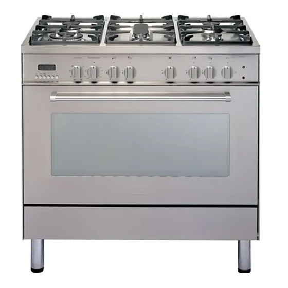
- Page 1 INSTALLATION and SERVICE INSTRUCTIONS USE and CARE INSTRUCTIONS D906GWF DUAL FUEL COOKER distributed by DèLonghi Pty Ltd...
-
Page 2: Product Label
Dear Customer, Thank you for having purchased and given your preference to our product. The safety precautions and recommendations reported below are for your own safety and that of others. They will also provide a means by which to make full use of the features offered by your appliance. - Page 3 FIRST TIME USE THE OVEN It is advised to follow these instructions: Clean the interior of the oven with cloth soaked in water and detergent (neutral) then dry carefully. Fit the wire racks as described at chapter “Use and care”. Insert shelves and tray.
-
Page 4: Important Precautions And Recommendations
IMPORTANT PRECAUTIONS AND RECOMMENDATIONS After having unpacked the appliance, check to ensure that it is not damaged. In case of doubt, do not use it and consult your supplier or a professionally qualified techni- cian. Packing elements (i.e. plastic bags, polystyrene foam, nails, packing straps, etc.) should not be left around within easy reach of children, as these may cause serious injuries. -
Page 5: Installation
INSTALLATION CAUTION: This appliance must be installed in accordance with these installation instructions. This appliance shall only be serviced by authorized personnel. This appliance is to be installed only by an authorised person. Incorrect installation, for which the manufacturer accepts no responsibility, may cause personal injury of damage. - Page 6 CLEARANCES Installation clearances and protection of combustible surfaces shall comply with the current local regulations eg. AG 601 (AS 5601) Gas Installations code. Installation shall comply with the dimension in Fig 1 bearing in mind that Overhead Clearances In no case shall the clearances between the highest part of the cooker be less than 600mm or for an overhead exhaust fan 750mm.
-
Page 7: Fitting The Adjustable Feet
FITTING THE ADJUSTABLE FEET The adjustable feet must be fitted to the base of the cooker before use. Rest the rear of the cooker an a piece of the polystyrene packaging exposing the base for the fitting of the feet. Fit the 4 legs by screwing them tight into the support base as shown in figure 3. -
Page 8: Moving The Cooker
MOVING THE COOKER WARNING When raising cooker to upright position always ensure two people carry out this manoeuvre to prevent damage to the adjustable feet (fig. 5). Figure 5 WARNING WARNING Be carefull: do not lift the cooker When moving cooker to its final posi- by the door handle when raising tion DO NOT DRAG (fig. -
Page 9: Anti-Tilt Bracket
ANTI-TILT BRACKET Fixing the anti-tilt bracket: After you have located where the cooker is to be positioned mark, on the wall, the place where the 2 screws of the anti-tilt bracket have to be fitted. Please fol- low the indications given in the drawing below. Make two holes of diameter 8mm diameter on the wall and insert the plastic plugs. - Page 10 BACKGUARD Before installing the cooker, assemble the backguard “C” (fig. 9). The backguard “C” can be found packed at the rear of the cooker. Before assembling remove any protective film/adhesive tape. Remove the two spacers “A” and the screw “B” from the rear of the cooktop. Assemble the backguard as shown in figure 9 and fix it by screwing the central screw “B”...
-
Page 11: Gas Supply
GAS SUPPLY: The connection must be executed by an authorised person according to the rele- vant standards. Before connecting the appliance to the gas main, mount the brass conical adaptor onto the gas inlet pipe, upon which the gasket has been placed (figures 10-11). Conical adaptor and gasket are supplied with the appliance (packed with conver- sion kit for use with Natural gas or Propane gas). - Page 12 1. After connecting the gas supply, check the piping and connections for leaks using a soap and water solution. The presence of bubbles indicates a leak, tighten or replace connections as appropriate. Warning: Do not use any naked flame to check for leaks. 2.
- Page 13 CONVERSION PROCEDURE (to convert to LPG Propane) REPLACING THE INJECTORS This appliance is suitable for use with Natural gas or Propane gas (check the “gas type” sticker attached to the appliance). A label stating the type of gas used after replacing the injectors must be attached at the rear of the appliance, in proximity of the gas inlet connection.
- Page 14 MINIMUM BURNER SETTING ADJUSTMENT Check whether the flame spreads to all burner ports when the burner is lit with the gas tap set to the minimum position. If some ports do not light, increase the minimum gas rate setting. Check whether the burner remains lit even when the gas tap is turned quickly from the maximum to the minimum position.
-
Page 15: Lubrication Of The Gas Taps
TABLE FOR THE CHOICE OF THE INJECTORS Natural gas Propane gas 2.75 Test Point Pressure [kPa] Injector Injector Orifice Dia. Consumption Orifice Dia. Consumption BURNER [mm] [MJ/h] [mm] [MJ/h] 0.85 3.60 0.53 3.60 Auxiliary (A) 1.12 6.30 0.70 6.30 Semi-rapid (SR) 1.65 13.30 0.95... -
Page 16: Using The Oven For The First Time
USE and CARE CAUTION: This appliance must be used only for the task it has explicitly been designed for, that is for domestic cooking of foodstuffs. Any other form of usage is to be con- sidered as inappropriate and therefore dangerous. Do NOT place combustible materials or products on this appliance at any time. -
Page 17: Grease Filter
GREASE FILTER A special screen is provided at the back of the oven to catch grease particles, mainly when meat is being roasted (fig. 18). When backing pastry etc. this filter should be removed. Always clean the filter after cooking as any solid residues on it might adversely affect the oven performance. -
Page 18: Gas Burners
GAS HOB Figure 20 GAS BURNERS Natural Gas Propane gas MJ/h MJ/h 1. Auxiliary burner (A) 2. Semi-rapid burner (SR) 3. Fish burner (FB) 10.6 10.6 4. Triple ring burner (TC) 13.3 11.9... - Page 19 LIGHTING GAS BURNERS FITTED WITH SAFETY VALVE DEVICE AND ELECTRONIC IGNITION Figure 21 Check that the electricity is switched on to allow spark igni- tion. Make sure that all controls are turned to zero. The gas flow to the burners is controlled by taps with a safety cutout device.
- Page 20 CHOICE OF BURNER The burner must be chosen according to the diameter of the pans and energy required. For optimum efficiency uso a wok or pan no smaller than 230mm diameter. Figure 22 do not use pans with concave or convex bases Burners Pan diameter Auxiliary...
- Page 21 CORRECT USE OF TRIPLE-RING BURNER The flat-bottomed pans are to be placed directly onto the pan-support. To use the WOK, you must place the wok stand in the CORRECT position as shown in Fig. 23-24. Figure 23 Figure 24 WRONG CORRECT...
-
Page 22: Multifunction Oven
MULTIFUNCTION OVEN Figure 25 CONTROL PANEL - Controls description 1. Oven switch knob 2. Oven thermostat knob 3. Front left burner control knob 4. Rear left burner control knob 5. Fish burner control knob 6. Rear right burner control knob 7. -
Page 23: Operating Principles
OPERATING PRINCIPLES Heating and cooking in the MULTI-FUNCTION oven are obtained in the following ways: a. by normal convection The heat is produced by the upper and lower heating elements. b. by forced convection The fan draws in air contained within the oven housing at the rear of the oven and forces it over the circular heating element. -
Page 24: Oven Light
OVEN LIGHT By setting the knob to this position, only the oven light comes on (15 W). It remains on in all the cooking modes. TRADITIONAL BAKE The upper and lower heating elements come on. The heat being dispersed by natural convection. -
Page 25: Fan Grill
FAN FORCED The circular element and fan come on. The heat is dispersed by forced convection and the temperature can be varied to between 50° and 225°C via the thermostat knob. The oven does not require preheating. Recommended for: Food which has to be well-cooked outside and soft or rosy inside, for example lasagne, lamb, roast beef, whole fish etc. -
Page 26: Cooking Advice
COOKING ADVICE STERILIZATION Sterilization of foods to be conserved, in full and hermetically sealed jars, is done in the following way: a. Set the switch to position b. Set the thermostat knob to position 185 °C and preheat the oven. c. - Page 27 ROTISSERIE Figure 27 (Fig. 28) This is used for spit roasting under the grill and comprises: an electric motor fitted to the rear of the oven a stainless steel skewer provided with slide-out heatless handgrip and two sets of adjustable forks a skewer support to be fitted in the middle runner.
- Page 28 RECOMMENDED COOKING TEMPERATURE Food °C °F Shelf Cooking Mark Position Time (approx) CAKES Victoria sandwich 2 or 3 20-25 mins Small cakes/buns 1 and 2 15-20 mins Maidera cake 2 or 3 20 mins 3 /4 Fruit cake hours 1 /2 Rich fruit cake 3 or 4 hours...
-
Page 29: Electronic Programmer
ELECTRONIC PROGRAMMER The electronic programmer is a device which groups together the following functions: 24 hours clock with illuminated display Timer (up to 23 hours and 59 minutes) Program for automatic oven cooking Program for semi-automatic oven cooking Description of the buttons: Timer Cooking time End of cooking time... -
Page 30: Electronic Clock
ELECTRONIC CLOCK (fig. 30) The illuminated figures on the clock represent hours and minutes on 24 hour clock. When first connected, or after a power failure, three zeros will flash on the display. To set the time press the button and then the Please note that changing the hour button deletes any cooking program. -
Page 31: Electronic Timer
ELECTRONIC TIMER The timer program consists only of a buzzer which may be set for a maximum period of 23 hours and 59 minutes. If AUTO is flashing on the panel, push the button. To set the time, push the button and the until you obtain the desired time in the panel (fig. -
Page 32: Automatic Oven Cooking
AUTOMATIC OVEN COOKING To cook food automatically in the oven, it is necessary to: 1.Set the length of the cooking time 2.Set the end of the cooking time 3.Set the temperature and the oven cooking program. These operations are performed as follows: 1.Set the length of the cooking time by pushing the button and the button to... -
Page 33: Semi - Automatic Cooking
SEMI - AUTOMATIC COOKING This function is only used to set the END of the cooking time of the oven. There are two ways of setting this function. 1. Set the length of the cooking time by pushing the button and the button to advance, or to go backwards (Fig. -
Page 34: Cleaning And Maintenance
Cleaning and Maintenance Maintenance Description Period Daily • Clean gas cooktop as per instructions below • Remove burner caps, burner rings & base and clean using non abrasive detergent & rinse in cold water & dry thoroughly Monthly before replacing back on hob •... - Page 35 OVEN The oven with smooth enamel must be cleaned after every use, using suitable prod- ucts. Please note that after using the oven for 30 minutes on the highest temperature eliminates most grime reducing it to ashes. Do not use abrasive substances to clean the oven. ADVICE FOR USE AND MAINTENANCE OF CATALYTIC PANELS The catalytic panels are covered with special microporous enamel which absorbs and...
- Page 36 BURNERS Figure 37 They can be removed and washed only with soapy water. Detergents can be used but must not be abrasive or corrosive. Do not use abrasive sponges or pads. Do not put in dishwasher. After each cleaning, make sure that the burner-caps, as well as the burners, have been well wiped off and CORRECTLY POSITIONED.
-
Page 37: Storage Compartment
REMOVAL OF THE INNER GLASS DOOR PANEL The inner glass door panel can easily be removed for cleaning by unscrew- ing the four screws (fig. 40). When re-assembly ensure that the inner glass is correctly positioned and do not over tighten the screws. Figure 40 STORAGE COMPARTMENT The storage compartment is accessible through the pivoting panel. -
Page 38: Replacing The Oven Light
GRILL HEATING ELEMENT The heating element is self-cleaning and does not require maintenance. REPLACING THE OVEN LIGHT Before any maintenance is started involving electrical parts of the appliance, it must be disconnected from the power supply. The bulb must be a type resistant to high temperatures (300° C). OVEN TRAY Figure 42 The oven tray must be correctly plac-... -
Page 39: Dismantling The Door
Figure 44a DISMANTLING THE DOOR Please operate as follows: Open the door completely. The swivel retainers of the rh and lh hinges (fig. 44a) are hooked onto the metal bar above them (fig. 44b). Lift the oven door slightly. The notch on the bottom of the hinge will disengage (fig. - Page 40 Service and Maintenance If the ignition spark fails to ignite or does not light the gas, check the following items before calling our Customer Service Centre to obtain the nearest Authorised Service Agent: Burner is reassembled and located correctly. Spark electrode and white ceramic are clean and dry. 240 VAC power supply is connected.
-
Page 41: Wiring Diagram
WIRING DIAGRAM ELECTRIC DIAGRAM KEY Ignition coil Oven switch Rotisserie Rotisserie switch Thermal overload Thermostat Thermostat pilot lamp Oven lamp Terminal block Oven programmer Earth connection Top element Grill element Line pilot lamp Cooling fan Bottom element Circular element Ignition switches group... - Page 43 Descriptions and illustrations in this booklet are given as simply indicative. The manufacturer reserves the right, considering the characteristics of the models described here, at any time and without notice, to make eventual necessary modifications for their construction or for commercial needs.
- Page 44 cod. 1102331 ß2...
Need help?
Do you have a question about the D906GWF and is the answer not in the manual?
Questions and answers
I HAVE A D906GWF DUAL FUEL COOKER. THE HEATING ELEMETS ARE WORKING BUT NOT IN COMBINATION WITH THE FAN ON MULIT-FUNCTION. IT WONT GET OR STAY HOT. WHAT DO I NEED TO DO TO FIX THIS PROBLEM ?
If the heating elements work but do not function with the fan in multi-function mode on the DèLonghi D906GWF dual fuel cooker, the following steps can be taken:
1. Check the fan operation: Ensure the fan is running in multi-function mode. The fan is essential for forced convection and forced semi-convection modes.
2. Confirm electrical connections: Verify that the appliance is correctly connected to the mains power and that the voltage and cable specifications match the rating plate.
3. Inspect the fan motor: A faulty fan motor may prevent proper air circulation. If the fan does not turn on, it may need to be repaired or replaced.
4. Examine the multi-function selector: The mode selector switch may be faulty and not properly activating the fan with the heating elements.
5. Check internal components: Ensure internal wiring and connections between the fan and heating elements are intact and not damaged.
6. Consult a qualified technician: If the issue persists, professional service may be required to diagnose and repair electrical or mechanical faults.
Always disconnect the appliance from the mains before performing any inspection or maintenance.
This answer is automatically generated