Download Print this page

JVC AV-29FH1BUG Service Manual

Hide thumbs Also See for AV-29FH1BUG:

Advertisement

SERVICE MANUAL
9
2003
YA008
1
PRECAUTION. . . . . . . . . . . . . . . . . . . . . . . . . . . . . . . . . . . . . . . . . . . . . . . . . . . . . . . . . . . . . . . . . . . . . . . . . 1-3
2
SPECIFIC SERVICE INSTRUCTIONS . . . . . . . . . . . . . . . . . . . . . . . . . . . . . . . . . . . . . . . . . . . . . . . . . . . . . . 1-4
3
DISASSEMBLY . . . . . . . . . . . . . . . . . . . . . . . . . . . . . . . . . . . . . . . . . . . . . . . . . . . . . . . . . . . . . . . . . . . . . . . 1-5
4
ADJUSTMENT . . . . . . . . . . . . . . . . . . . . . . . . . . . . . . . . . . . . . . . . . . . . . . . . . . . . . . . . . . . . . . . . . . . . . . . . 1-8
5
TROUBLESHOOTING . . . . . . . . . . . . . . . . . . . . . . . . . . . . . . . . . . . . . . . . . . . . . . . . . . . . . . . . . . . . . . . . . 1-12
COPYRIGHT © 2003 VICTOR COMPANY OF JAPAN, LIMITED
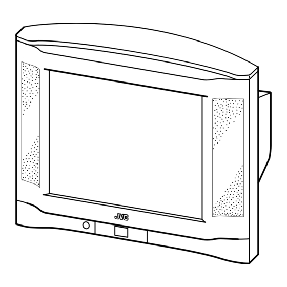
COLOUR TELEVISION
AV-29FH1BUG,
AV-29FH1SUG

TABLE OF CONTENTS

No.YA008
2003/9

Advertisement

loading

Summary of Contents for JVC AV-29FH1BUG

  • Page 1: Table Of Contents

    COLOUR TELEVISION YA008 2003 AV-29FH1BUG, AV-29FH1SUG TABLE OF CONTENTS PRECAUTION............... . . 1-3 SPECIFIC SERVICE INSTRUCTIONS .
  • Page 2 SPECIFICATION Contents Items AV-29FH1BUG AV-29FH1SUG Dimensions ( W 81.2cm 60.1cm 52.2cm Mass 40kg TV RF System CCIR (B/G, D/K, I , L/L') Colour System PAL / SECAM / NTSC (Only in EXT mode) Stereo System A2 (B/G, D/K) / NICAM (B/G, I, D/K, L)
  • Page 3: Precaution

    SECTION 1 PRECAUTION SAFETY PRECAUTIONS (1) The design of this product contains special hardware, (8) When service is required, observe the original lead dress. many circuits and components specially for safety Extra precaution should be given to assure correct lead purposes.
  • Page 4: Specific Service Instructions

    SECTION 2 SPECIFIC SERVICE INSTRUCTIONS 21-pin Euro connector (SCART) : EXT-1/EXT-2 Pin No. Signal designation Matching value EXT-1 EXT-2 AUDIO R output 500mV(rms) (Nominal), Low impedance Used (TV OUT) Used (LINE OUT) AUDIO R input 500mV(rms) (Nominal), High impedance Used (R1) Used (R2) AUDIO L output 500mV(rms) (Nominal), Low impedance...
  • Page 5: Disassembly

    SECTION 3 DISASSEMBLY DISASSEMBLY PROCEDURE 3.1.1 REMOVING THE REAR COVER 3.1.5 CHECKING THE PW BOARD (1) Unplug the power cord. • To check the back side of the PW Board. (2) Remove the 8 screws [A]. (1) Pull out the MAIN PWB. (Refer to REMOVING THE MAIN (3) Remove the 1 screw [B].
  • Page 6 REPLACEMENT OF MEMORY IC 3.2.1 MEMORY IC This TV use memory IC. In the memory IC, there are memorized data for correctly operating the video and deflection circuits. When replacing memory IC with a blanking memory IC, the set is automatically memorized following SERVICE MANU initial data. 3.2.2 SERVICE MENU ADJUSTMENT ITEMS 3.2.3 FACTORY SETTING There are 21 SERVICE ADJUSTMENT ITEMS.
  • Page 7 REPLACEMENT OF CHIP COMPONENT 3.3.1 CAUTIONS (1) Avoid heating for more than 3 seconds. (2) Do not rub the electrodes and the resist parts of the pattern. (3) When removing a chip part, melt the solder adequately. (4) Do not reuse a chip part after removing it. 3.3.2 SOLDERING IRON (1) Use a high insulation soldering iron with a thin pointed end of it.
  • Page 8: Adjustment

    SECTION 4 ADJUSTMENT ADJUSTMENT PREPARATION (1) There are 2 ways of adjusting this TV : One is with the REMOTE CONTROL UNIT and the other is the conventional method using adjustment parts and components. (2) Make sure that connection is correctly made AC to AC power source. (3) Turn on the power of the TV and measuring instruments for warning up for at least 30 minutes before starting adjustments.
  • Page 9 ADJUSTMENT PROCEDURE 4.4.1 LOCAL OSCILLATOR ADJUSTMENT Measuring Item Test point Adjustment part Description instrument Signal (1) Receive a colour bar pattern signal. adjustment generator (2) The frequency of the signal carrier must be accurate AFT coil : (L150) (Max +/-10kHz deviation from the nominal channel Remote [MAIN PWB] frequency).
  • Page 10 4.4.4 SCREEN ADJUSTMENT Measuring Item Test point Adjustment part Description instrument SCREEN Signal G2-SCREEN (1) Receive a colour bar pattern signal. adjustment generator (2) Select < G2-SCREEN >. SCREEN VR (3) Adjust the SCREEN VR on the FBT to bring the Remote [On FBT] cursor to central position.
  • Page 11 Measuring Item Test point Adjustment part Description instrument HORIZONTAL Signal PARABOLA (1) Receive a cross-hatch pattern signal. GEOMETORY generator HOR WIDTH (2) Select < PALABOLA >(Side pin), < HOR WIDTH > adjustment CORNER (Horizontal width), < CORNER >(Top/bottom Remote HOR PARAL corner), <...
  • Page 12: Troubleshooting

    SECTION 5 TROUBLESHOOTING This service manual does not describe TROUBLESHOOTING. 1-12 (No.YA008)
  • Page 13 VICTOR COMPANY OF JAPAN, LIMITED AV & MULTIMEDIA COMPANY VIDEO DISPLAY CATEGORY 12, 3-chome, Moriya-cho, kanagawa-ku, Yokohama, kanagawa-prefecture, 221-8528, Japan (No.YA008) Printed in Japan...
  • Page 41 No.YA008...
  • Page 42 No.YA008...
  • Page 43 No.YA008 No.YA008...
  • Page 44 No.YA008 No.YA008...
  • Page 45 No.YA008 No.YA008...
  • Page 46 No.YA008 2-10 No.YA008...
  • Page 48 VICTOR COMPANY OF JAPAN, LIMITED AV & MULTIMEDIA COMPANY VIDEO DISPLAY CATEGORY 12, 3-chome, Moriya-cho, kanagawa-ku, Yokohama, kanagawa-prefecture, 221-8528, Japan (No.YA008) Printed in Japan...

This manual is also suitable for:

Av-29fh1sug