Table of Contents
Advertisement
BW4
BW5
NOTE: Read the entire instruction manual before starting the
installation.
TABLE OF CONTENTS
. . . . . . . . . . . . . . . . . . . . . . . . . . . . . . . . . .
. . . . . . . . . . . . . . . . . . . . . . . . . . . . . . . .
. . . . . . . . . . . . . . . . . . . . . . . . . . . . . . . .
. . . . . . . . . . . . . . . . . . . . . . . . . . . . . . . . . . .
. . . . . . . . . . . . . . . . . . . . . . . . . . . .
. . . . . . . . . . . . . . . . . . . . . . . . . . . .
. . . . . . . . . . . . . . . . . . . . . . . . . . .
. . . . . . . . . . . . . . . . . . . . . . . . . . . . . . . . .
. . . . . . . . . . . . . . . . . . . . . . . . . . . . . . . . . . . .
. . . . . . . . . . . . . . . . . . . . . . . . . . . . .
. . . . . . . . . . . . . . . . . . . . . . . . . . . . . . . . . . . . . . . .
. . . . . . . . . . . . . . . . . . . . . . . . . . .
. . . . . . . . . . . . . . . . . . . . . . . . . . . . . . . . . .
. . . . . . . . . . . . . . . . . . . . . . . . . . . . . . . . . . . . . . . .
. . . . . . . . . . . . . . . . . . . . . . . . . .
. . . . . . . . . . . . . . . . . . . . . . . . . . . .
. . . . . . . . . . . . . . . . . . . . . . . . . . . . . . . . . .
. . . . . . . . . . . . . . . . . . . . . . . . . . . . . . . . . . . . .
. . . . . . . . . . . . . . . . . . . . . . . . . . . . . . . . . . . .
. . . . . . . . . . . . . . . . . . . . . . . . . . . . .
. . . . . . . . . . . . . . . . . . . . . . . . . . . . . . . . . . . .
. . . . . . . . . . . . . . . . . . . . . . . . . . . . . . . . . . . . . . .
Installation Instructions
PAGE
. . . . . . . . . . . . . . . . . . . . . . . .
. . . . . . . . .
. . . . . . . . . . . . . . . . . . . . .
. . . . . . . . . . . . . . . . . . .
. . . . . . . . . . . . . . . . . .
. . . . . . . . . . . . . . . . . . . . . . . . .
. . . . . . . . . . . . . . . . . . . .
. . . . . . . . . . . . . . . . . . . . . . .
. . . . . . . . . . . . . . . . . . . . . . . . .
. . . . . . . . . . . . . . . . .
. . . . . . . . . . . . . . . .
Sizes 140,000 through 280,000
ASME
1
3
3
4
4
SAFETY CONSIDERATIONS
4
Installing and servicing heating equipment can be hazardous due
4
to oil and electrical components. Only trained and qualified
personnel should install, repair, or service heating equipment.
4
Untrained personnel can perform basic maintenance functions
7
such as maintaining water level. All other operations must be
performed by trained service personnel. When working on
8
heating equipment, observe precautions in literature, on tags, and
10
on labels attached to or shipped with unit and other safety
10
precautions that may apply. Recognize safety information. This is
the safety- -alert symbol . When you see this symbol on unit or in
10
instructions and manuals, be alert to potential for personal injury.
12
Understand
the
13
CAUTION, and NOTE. These words are used with the
safety- -alert symbol. DANGER identifies the most serious
13
hazards which will result in severe personal injury or death.
13
WARNING signifies hazards which could result in personal
13
injury or death. CAUTION is used to identify unsafe practices
which may result in minor personal injury or product and
13
property damage. NOTE is used to highlight suggestions which
13
will result in enhanced installation, reliability, or operation. Read
and obey the following rules to ensure safe installation and
13
operation:
15
1. Read the Owner's Manual carefully for safe operation.
16
Failure to follow the rules of safe operation and the
16
instructions can cause a
malfunction of the boiler and result in death, serious
16
bodily injury, and/or property damage.
16
2. Check local codes and utility requirements before
16
installation. The installation must be in accordance with
their directives, or follow NFPA 31-Installation of Oil
16
Burning Equipment, latest revision.
16
3. Before servicing, allow boiler to cool. Always shut off any
17
electricity and oil to boiler when working on it. This
prevents any electrical shocks or burns.
17
4. Inspect oil line and connections for leaks.
22
5. Be certain oil burner nozzle is size required. Overfiring
22
will result in early failure of boiler sections. This causes
dangerous operation.
6. Never vent this boiler into an enclosed space. Always vent
to the outside. Never vent to another room or inside a
building.
Oil---Fired Cast Iron
Hot Water Boilers
ama
®
signal
words
DANGER,
WARNING,
Advertisement
Table of Contents

Subscribe to Our Youtube Channel
Related Manuals for CAC / BDP BW4


Summary of Contents for CAC / BDP BW4
-
Page 1: Table Of Contents
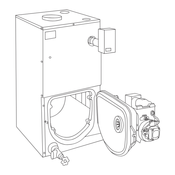
Oil---Fired Cast Iron Hot Water Boilers Sizes 140,000 through 280,000 Installation Instructions NOTE: Read the entire instruction manual before starting the installation. TABLE OF CONTENTS PAGE ASME SAFETY CONSIDERATIONS ......INTRODUCTION . - Page 2 A02217 Fig. 1 - - Model BW4/BW5 7. Be sure there is adequate air supply for complete are purged, for boiler installations using float type vents, combustion. the air vents should be closed for normal operation. If air is heard or noticed by loss of heat, purge the system and 8.
-
Page 3: Introduction
The to be sure they are all done. BW4(5)RAH280ABAA can only be fired at an input of 280,000 Btuh or 245,000 Btuh. The following steps are all necessary for proper installation and... -
Page 4: General Information
For BW4RAH models equipped with Riello burners: If location is to be changed, additional materials as well as an adequate base will be required. The following rules apply: There are two different Riello burners used on the BW4RAH boilers, the F5 and F10 burner. The BW4RAH000280AAAA is 1. - Page 5 CIRCULATING PUMP IN SUPPLY LINES ELECTRIC LINE SERVICE LINE AUTOMATIC FILL VALVE ENTRANCE AND SHUTOFF SWITCH DIAPHRAGM EXPANSION TANK 2 IN. FILL PIPE OVERCURRENT DRAFT PROTECTED REGULATOR VENT PIPE SAFETY SWITCH MINIMUM 2 IN. ID VENT PIPE LINES TO OTHER APPLIANCES RELIEF VALVE TO OUTSIDE...
- Page 6 Table 1 - - Boiler Ratings and Capacities (Cont.) **HEATING FIRING MIN. DIMENSIONS--- IN TANKLESS INPUT I=B=R SHIPPING WITH TANK CAPACITY RATE CHIMNEY HEATER A.F.U.E RATING LESS COIL *MBH WEIGHT *MBH SIZE/HEIGHT ##G.P.M. *MBH 0.65 #86.3 8” X8” X15’ 14 1/2 2.90 BW5BAH140 0.75...
-
Page 7: Boilers With Tankless Heater Coil
3. When communicating with the outdoors through horizontal ducts, each opening shall have a minimum free VENTILATING area of 1 sq. in. per 2000 Btuh of total input rating of all GRILLE equipment in the enclosure. 4. When ducts are used, they shall be of the same cross- -sectional area as the free area of the openings to which they connect. -
Page 8: Installation System Piping
* Gallon of water per minute heated from 40_ F to 140_ F with 200_ F boiler water, intermittent draw. Tankless heater is factory installed on BW5 models, field installed accessory on BW4 models. responsible for any water damage. Connect a drain line of UNTEMPERED the same pipe size (3/4- -in.) to carry any water away to a... - Page 9 RETURN FROM SYSTEM DRAIN VALVE MAIN SHUTOFF FOR POWER VALVE PURGING AUTOMATIC FILL VALVE SUPPLY TO SYSTEM SHUTOFF VALVE BOILER SERVICE FILTROL WITH FILL LINE WITH SHUT OFF VALVE AIR PURGER AQUASTAT BOILER DRAIN VALVE A01032 Fig. 9 - - Circulator on Supply Pumping Away ADJUST THE TWO THROTTLINE VALVES TO RETURN FROM SYSTEM MAINTAIN AT LEAST 120...
-
Page 10: Chimney And Chimney Connection
Table 4 – Recommended Minimum Chimney Sizes FIRING RATE CHIMNEY HEIGHT NORMAL CHIMNEY AREA (IN.) ROUND LINER INSIDE SQUARE LINER INSIDE (GPH) (FT.) DIAMETER (IN.) DIMENSIONS (IN.) 0.60 to 1.30 8 X 8 6--- 3/4 X 6--- 3/4 1.31 to 1.80 8 X 8 6--- 3/4 X 6--- 3/4 1.81 to 2.00... - Page 11 It is possible for a tank to become “water- -logged” (filled with tank (a) in the supply line with the circulator located after the water). It can also become overfilled with air. This can happen expansion tank or (b) off the e3/4- -in. tapping provided on the top after filling system with new water.
-
Page 12: Filling Boiler
Table 6 – Piping Water Volumes pre- -purge the combustion chamber and the oil pump to bring the supply oil pressure up to its set point helping to provide a clean PIPE SIZE COPPER PIPE FACTOR STEEL PIPE FACTOR light off. 1/2--- IN. -
Page 13: Operating Boiler
Draft Regulators (Provided) until hand is again pointing to same pressure reading. Instructions are packaged with valve. A draft regulator is required. It should preferably be mounted in OPERATING BOILER smoke pipe. Use a draft gage to adjust to proper opening. When burner air supply and draft are properly adjusted, combustion chamber draft will be approximately - -0.01 to - -0.02 in. - Page 14 BECKETT AFG VARIABLE (V1) HEAD ADJUSTMENTS AND SETTINGS LOCATION OF HEAD AT "D" WITNESS POSITION ON ADJUSTING PLATE MARK PRIMARY "Z" ADJUSTING DIMENSION PLATE HOLD DOWN 3-3/4" 1/32" SCREW SECONDARY ADJUSTING PLATE KNURLED ACORN NUT/ LOCK WASHER "V1" AIR TUBE COMBINATION A06664 Fig.
-
Page 15: Oil Burner Maintenance
A06507 Fig. 17 - - Riello 40- -F10 Burner Electrode Adjustments Oil Burner Maintenance Clean and adjust as per manufacturer’s recommendations so as to maintain reliable ignition of oil. The following preventative maintenance items should be E. Nozzle performed annually, preferably prior to the heating season. Replace so as to maintain safe and reliable combustion efficiency. -
Page 16: Checking And Adjusting Controls
Table 8 – Riello Oil Burner Specifications BASE BOILER DELEVAN FIRING TURBULATOR/AIR OIL PUMP PRESSURE MODEL INPUT (BTUH) OIL NOZZLE RATE (GPM) SHUTTER SETTING (PSIG) BURNER 91,000 0.50--- 70ºW 0.65 0.5 / 2.0 105,000 0.65--- 70ºW 0.75 2.0 / 2.2 140,000 0.85--- 70ºW 1.00... -
Page 17: Oil Boiler/Burner Cleaning Instructions
Oil Boiler/Burner Cleaning Instructions OIL BOILER CLEANING NOTE: These are general instructions for cleaning an oil burner. OIL BOILER CLEANING For specifics, consult the burner manufacturer’s instructions 1. Shut off all electrical power to the boiler/burner and shut 1. Make sure all electrical power to the boiler/burner and the off fuel oil supply. - Page 18 shutting off burner. Circulator pump remains running as 115V 60 CYCLE long as thermostat calls for heat. SUPPLY 7. If boiler water temperature falls 10_ below high limit 24 VOLT setting, contacts BR close energizing burner. THERMOSTAT 8. Thermostat is satisfied terminating call for heat. Relay coil 1K is de- -energized opening 1K1 and 1K2 contacts.
- Page 19 BOILER WITH TANKLESS HEATER COIL BOILER WITHOUT TANKLESS HEATER COIL COLOR CODE 24 VOLT THERMOSTAT 120/60/1 OVERCURRENT PROTECTED DISCONNECT FIELD WIRING B=BLACK W=WHITE LINE O=ORANGE NEUT Y=YELLOW 120V NEUTRAL LINE POWER L8124C VOLTAGE SUPPLY AQUASTAT CLASS II OVERCURRENT 24 V THERMOSTAT 24 VOLTS PROTECTED FIELD WIRING...
- Page 20 A06504 Fig. 21 - - Boilers Without Tankless Coil and Honeywell L8148 Aquastat Control...
- Page 21 F5 only A06505 Fig. 22 - - Boilers With Tankless Coil and Honeywell L8124C Aquastat Control and Riello Burners...
-
Page 22: Service Hints
Service Hints 240 F (116 C) Avoid inconvenience and service calls by checking these points before calling for service. SWITCH BREAKS ON RISE, TURNS BURNER have your service technician check any problem you are HI LIMIT OFF. CIRCULATOR SETTING unable to correct. OPERATES ON CALL 10 F (5.6 C) FOR HEAT. - Page 23 A01039 ITEM DESCRIPTION PART NUMBER Section Machined Back 403--- 00--- 008 Section Machined Middle 403--- 00--- 007 Section Machined Front 403--- 00--- 006 Nipple Machined 2--- in. --- (2--- in. cast iron push nipple) 433--- 00--- 976 Tie Rod 1/4X10 1/4 3 section 146--- 05--- 002 4 section...
- Page 24 A01040 ITEM DESCRIPTION PART NUMBER Section Machined Front 403–00–006 Stud TFL (Threaded Full Length) 3/8–16- - in. X 2–1/2- - in. 146–95–125 Whizlok Nut ZP (Zinc Plated) 3/8 146–95–126 Insulation Swing Door (Gemoclite Vacuum Formed Ceramic Fiber 2300°) 146–14–014 Hinge Machined 403–00–010 Rivet RD (Round) HD (Head) Separated Flange ZP 3/8- - in.
- Page 25 Table 12 – Riello Oil Burner Service Parts RIELLO OIL BURNER REPAIR PARTS Oil Burner Repair Parts--- Burner Not Shown Part Number Burner Motor 30A065101 Fuel Pump * 30A065401 Oil Solenoid Coil * * 30A064901 Oil Primary Control 530SE 30A064801 Electrodes 30A065301 Photo Cell...
- Page 26 Catalog No: IM---BW4R ---02 Printed in U.S.A. Edition Date: 10/06 Copyright 2006 CAC / BDP D 7310 W. Morris St. D Indianapolis, IN 46231 Replaces:IM- -BW4R Manufacturer reserves the right to change, at any time, specifications and designs without notice and without obligations.
Need help?
Do you have a question about the BW4 and is the answer not in the manual?
Questions and answers