Table of Contents
Advertisement
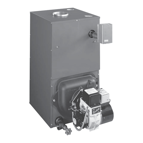
OIL FIRED CAST IRON
INSTALLATION, OPERATION &
MAINTENANCE MANUAL
Models
BW4BAH-91
BW4RAH-91
BW5BAH-91
BW5RAH-91
BW4BAH-105
BW4RAH-105
BW5BAH-105
BW5RAH-105
BW4BAH-140
BW4RAH-140
BW5BAH-140
BW5RAH-140
HOT WATER BOILER
(Series C)
BW4BAH-126
BW4RAH-126
BW5BAH-126
BW5RAH-126
BW4BAH-175
BW5RAH-175
BW5BAH-175
BW5RAH-175
BW4BAH-210
BW4RAH-210
BW5BAH-210
BW5RAH-210
BW4BAH-168
BW4RAH-168
BW5BAH-168
BW5RAH-168
BW4BAH-245
BW4RAH-245
BW5BAH-245
BW5RAH-245
Select Models
7310 WEST MORRIS ST.
INDIANAPOLIS, IN 46231
P/N# IM-BW4-01
[240009548, Rev. C [12/2012]
CAC/BDP
Advertisement
Table of Contents

Related Manuals for CAC / BDP BW4BAH-91


Summary of Contents for CAC / BDP BW4BAH-91
- Page 1 OIL FIRED CAST IRON HOT WATER BOILER INSTALLATION, OPERATION & MAINTENANCE MANUAL Models (Series C) BW4BAH-91 BW4BAH-126 BW4BAH-168 BW4RAH-91 BW4RAH-126 BW4RAH-168 BW5BAH-91 BW5BAH-126 BW5BAH-168 BW5RAH-91 BW5RAH-126 BW5RAH-168 BW4BAH-105 BW4BAH-175 BW4BAH-245 BW4RAH-105 BW5RAH-175 BW4RAH-245 BW5BAH-105 BW5BAH-175 BW5BAH-245 BW5RAH-105 BW5RAH-175 BW5RAH-245 BW4BAH-140...
-
Page 2: Table Of Contents
SAFETY NOTICES Safety Notices .............3 Introduction Boiler is a natural draft oil fi red hot water boiler comprised Boiler Ratings And Capacities ........4 of cast iron sections. Boiler is available with 3, 4, or 5 cast Fresh Air For Combustion........8 iron sections. -
Page 3: Boiler Ratings And Capacities
BOILER RATINGS AND CAPACITIES Figure 1 - Dimensions BOILER RATINGS AND CAPACITIES ‡NET DIMENSIONS INPUT Boiler BOILER MODEL NO. **HEATING AHRI (inches) A.F.U.E. Water CAPACITY RATING SEC. Capacity *Mbh WATER +gph *Mbh (US Gal.) *Mbh »BW(4,5)(B,R)AH-91 0.65 86.3 14½ »BW(4,5)(B,R)AH-105 0.75 85.2 14½... -
Page 4: Bw4Bah
SAFE INSTALLATION AND OPERATION WARNING WARNING Fire, explosion, burn, scald hazard. Use only Burn and scald hazard. Safety relief valve could number 2 fuel oil. Do not use gasoline, kerosene, discharge steam or hot water during operation. crankcase oil or any oil containing gasoline. Failure Install discharge piping per these instructions. -
Page 5: Bw4Bah
LOCATING THE BOILER Complete Prior To Installing Boiler. Place boiler in location centralized with the piping system and as close to chimney as possible. A. Verify you have selected the right size boiler with proper capacity. AHRI rating of boiler selected Boiler must be level. -
Page 6: Bw4Bah
LOCATING THE BOILER Figure 3 - Boiler With Piping System... -
Page 7: Fresh Air For Combustion
FRESH AIR FOR COMBUSTION EXAMPLE 2: Boiler Located in Confi ned Space WARNING Asphyxiation, fi re hazard. Do not obstruct air All Air from Inside the Building: Confi ned openings to combustion area. Follow instructions space shall be provided with two permanent openings below, to maintain adequate combustion air. - Page 8 FRESH AIR FOR COMBUSTION All Air from Outdoors: Confi ned space shall 3. When communicating with outdoors through be provided with two permanent openings, one horizontal ducts, each opening shall have commencing within 12 inches of top and commencing minimum free area of one square inch per 2,000 within 12 inches of bottom of enclosure.
-
Page 9: System Piping
SYSTEM PIPING Installation of boiler for new heating system, Figure 6a - Safety Relief Valve Installation Install all of radiation units (panels, radiators, baseboard, or tubing) and supply and return mains fi rst. After all heating system piping and components have been installed, make fi... - Page 10 SYSTEM PIPING Low Design Water Temperature Systems (Below Figure 7 - Bypass Piping Arrangement Diagram 140° F) And Large Water Content Systems > LOW DESIGN WATER TEMPERATURE • Signifi cant condensation may form in this boiler and/ SYSTEMS or venting system if boiler is operated with return temperatures of less than 120°F.
- Page 11 SYSTEM PIPING Figure 8 - System Piping Arrangement Zoning With Zone Valves > CIRCULATOR ON SUPPLY PIPING PUMPS AWAY FROM EXPANSION TANK NOTE: CIRCULATOR CAN ALSO BE INSTALLED ON RETURN PIPING. > PIPING ARRANGED FOR “POWER PURGING” AIR OUT OF SYSTEM PIPING, REFER TO THIS MANUAL’S SECTION ON “FILLING THE SYSTEM WITH WATER”...
- Page 12 SYSTEM PIPING Figure 9 - System Piping Arrangement Zoning With Circulators > CIRCULATOR ON SUPPLY PIPING PUMPS AWAY FROM EXPANSION TANK > PIPING ARRANGED FOR “POWER PURGING” AIR OUT OF SYSTEM PIPING, REFER TO THIS MANUAL’S SECTION ON “FILLING THE SYSTEM WITH WATER” OPTION #1...
- Page 13 SYSTEM PIPING Figure 10 - System Piping Arrangement Alternate Near Boiler Piping > PER THIS MANUAL, USE OPTION #2 IN “FILLING THE SYSTEM WITH WATER” > DIAPHRAGM EXPANSION TANK MOUNTED OFF THE BOILER > THIS PIPING ARRANGEMENT CAN BE USED WITH ZONE VALVES OR ZONE >...
- Page 14 SYSTEM PIPING Tankless Coil Piping Arrangement Burner Tankless Boiler Input Boilers may be factory packaged with tankless heater Input Rating Model (MBH) coil see fi gure below. Coil provides instantaneous heating Rate (gph) (gpm)‡ of water for domestic use if proper burner and water supply BW5(B,R)AH-91 0.65 2.90...
- Page 15 SYSTEM PIPING ARRANGEMENT Antifreeze added to boilers must be nontoxic, and PIPING WATER VOLUMES must be of type specifi cally intended for use in closed hydronic heating systems. Under no circumstances COPPER PIPE STEEL PIPE PIPE SIZE should automotive antifreeze be used. Antifreeze used FACTOR FACTOR in any boiler may reduce capacity by 10% or more and...
-
Page 16: Chimney And Chimney Connections
CHIMNEY AND CHIMNEY CONNECTIONS For oil fi red boilers for connections to vents or chimneys, WARNING vent installations shall be in accordance with applicable Fire Hazard. Maintain minimum vent pipe clearance provisions of INSTALLATION OF OIL BURNING EQUIPMENT, NFPA31 latest revision, and applicable provisions of local of 18”... -
Page 17: Typical Chimney Connection
TYPICAL CHIMNEY CONNECTION Figure 12 - Typical Chimney Connection Minimum height: • Must be at least 3ft. (.9m) higher than highest part of passage through roof. • Must be at least 2ft. (.7m) higher than any neighboring object within 10ft. (3m). •... -
Page 18: Electrical Connections
ELECTRICAL CONNECTIONS WARNING Electric Power Supply Installation must comply with the latest revision of the Electrical shock hazard. Turn OFF electrical power supply National Electrical Code, any other national, state, or local at service panel before making electrical connections. codes or regulations. Failure to do so could result in death or serious injury. -
Page 19: Filling The Boiler
FILLING THE BOILER How A Hot Water System Operates OPTION #2 Entire heating system (boiler, piping, and radiation units) is fi lled with water. As water in the boiler is heated, it • Close air vents on all radiation units. is circulated from top of boiler through supply main to •... -
Page 20: Operating The Boiler
OPERATING THE BOILER • Room used for supplying combustion air should be Start: Fill entire system with water. Vent all air from isolated from any area served by exhaust fans. system following section for Filling The Boiler. • Refer back to the section on Fresh Air For Combustion for additional sizing guidelines. - Page 21 OPERATING THE BOILER Final Burner Adjustments: Final burner adjustments Oil Burner Maintenance : For Beckett AFG, and Riello must be made using combustion test instruments. Refer to 40 F5, or F10 perform following preventative maintenance “Burner Settings”. Set burner accordingly. annually, preferably prior to heating season.
- Page 22 OPERATING THE BOILER Figure 13 -Burner Adjustments and Settings...
-
Page 23: Checking And Adjusting Controls
CHECKING AND ADJUSTING CONTROLS Locate thermostat fi ve feet above the fl oor on inside wall. NOTICE Locate thermostat to sense average room temperature, You or your installer must follow these instructions avoid the following: carefully. THERMOSTAT LOCATIONS TO AVOID DEAD WARNING HOT SPOTS... -
Page 24: Maintenance
MAINTENANCE Annually Diaphragm Expansion Tank : Recommend fl ue passages, combustion : Tank may become chamber area (target wall, fi re door insulation, water logged. Frequent automatic opening of safety relief durablanket), burner adjustment, control operation, and valve indicates water logging. High boiler temperature boiler seals (fi... -
Page 25: Oil Boiler / Burner Cleaning Instructions
OIL BOILER / BURNER CLEANING INSTRUCTIONS Oil Boiler Cleaning: Carefully vacuum soot accumulations from combustion chamber area, take care to not damage any of Shut off all electrical power to boiler / burner and shut refractory or blanket insulation. To gain access to off fuel oil supply. -
Page 26: Oil Burner Cleaning
OIL BURNER CLEANING These are general instructions for cleaning an oil burner. For specifi cs, consult burner manufacturer’s instructions. WARNING Electrical shock hazard. Turn OFF electrical power supply at service panel before making electrical connections. Failure to do so could result in death or serious injury. Verify all electrical power to boiler / burner and fuel supply to burner are shut off. -
Page 27: Service Hints
SERVICE HINTS You may avoid inconvenience and service calls by checking these points before you call for service: IF YOUR SYSTEM IS NOT HEATING OR NOT GIVING ENOUGH HEAT . . . POSSIBLE CAUSE WHAT TO DO Thermostat is not set correctly Reset thermostat Check fl... -
Page 28: Electrical Wiring
ELECTRICAL WIRING Figure 16 - Honeywell L7248L Control With Beckett AFG Burner... - Page 29 ELECTRICAL WIRING Figure 17 - Honeywell L7248L Control With Riello F5/F10 Burner...
-
Page 30: Equipment And Optional Accessories
EQUIPMENT AND OPTIONAL ACCESSORIES MAIN AIR VENT: for down fl ow systems or diaphragm CIRCULATOR (provided) Every forced hot water system requires circulator. Separate type expansion tanks (not provided) circulator or zone valve is required for each zone, if there Before system is fi... - Page 31 NOTES...
- Page 32 CAC/BDP 7310 West Morris St. Indianapolis, IN. 46231...
Need help?
Do you have a question about the BW4BAH-91 and is the answer not in the manual?
Questions and answers