Minelab GPX 5000 Instruction Manual
Gpx 5000; gpx 4800
Hide thumbs
Also See for GPX 5000:
- Instruction manual (51 pages) ,
- Quick start manual (48 pages) ,
- Quick manual (2 pages)
Table of Contents
Advertisement
Quick Links
Advertisement
Table of Contents

Related Manuals for Minelab GPX 5000


Summary of Contents for Minelab GPX 5000
- Page 1 Instruction Manual...
-
Page 2: Quick Start
It should be smooth with only minor fluctuations. You are now ready to start searching! Minelab is always interested in your opinions. If you have any questions or comments regarding your GPX Series or any other Minelab product, please feel free to contact us directly or via your local Authorised Minelab dealer. - Page 3 Electronic Timing Alignment (SETA) and the latest in high-tech analogue components combined with advanced digital processing. The GPX 5000 and GPX 4800 will locate gold in all types of ground, especially highly mineralised ground conditions, with greater efficiency than any previous detector.
-
Page 4: Table Of Contents
2 Contents Quick Start Introducing the GPX 5000 and GPX 4800 List of Parts Assembly Adjusting the Detector for Comfortable Detecting Charging the Battery Battery LED Patterns Taking Care of Your Battery Detecting Basics Detector Sounds Front Control Panel Rear Control Panel... - Page 5 LCD Backlight Battery Test / Viewing the battery voltage. Volume Limit / Setting the maximum volume of all sounds. Ground Balance Type Ground Balance Procedure for Specific Special / Soil/Timings. Manual Tune / Reducing electrical interference. Changing Search Modes / Via the LCD. Motion / Adjusting sweep speed.
- Page 6 Technology' (DVT). This ensures an accurate Ground Balance to provide maximum sensitivity and depth in all ground types. The GPX 5000 offers a total of eight Timing options, the GPX 4800 offers six; each incorporating the all-new SETA Timings stability technology.
- Page 7 Used to control the built-in amplifier which conditions. Fine Gold, Salt/Gold and Coin/ affects the volume of target signals. It is Relic are new timings for the GPX 5000. Coin/ active with both headphones and an external Relic is also new to the GPX 4800.
-
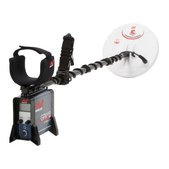
Page 8: List Of Parts
6 List of Parts Armrest (2 sections) 11" Coil Lower Shaft Upper Shaft Control Box Battery Harness Bungy Cord Clamp Bungy Cord (Bow Knuckle) with Bolt and Wingnut... - Page 9 Armrest Straps Armrest Cover Armrest Wingnuts Armrest Bolts Velcro Tabs Lower Shaft Washers Lower Shaft Wingnut Lower Shaft Bolt Lithium-ion Battery Power Cable Handle Headphones (with Quick-Trak Button) Vehicle Charger Adaptor Mains Charger Adaptor Instruction Manual & Warranty Card...
-
Page 10: Assembly
8 Assembly Attaching the Coil to the Lower Shaft: 1 Plug the two rubber washers into the holes on either side of the lower shaft. 2 Ensure that the spring loaded pin of the lower shaft is pointing downwards. Slide the lower shaft into the bracket on top of the coil. - Page 11 Attaching the Lower Shaft to the Upper Shaft: 1 With the twistlock facing away from you, rotate the twistlock of the upper shaft clockwise to ensure it is loosened, as pictured left. 2 Compress the spring loaded pin of the lower shaft. Slide the lower shaft into the upper shaft until the pin reaches an adjustment hole.
- Page 12 10 Assembly Continued... Attaching the Armrest Straps to the Armrest: 1 Press both strap studs onto the armrest studs. 2 Push the armrest straps through the slots in the armrest cover and then slide the cover over the armrest. Connecting the Control Box to the Upper Shaft: 1 Place the detector on a flat surface, with the handle facing upwards.
- Page 13 Always ensure that the control box is turned off before connecting or disconnecting the coil to avoid damage to the detector's electronics. Connecting the Coil Cable: 1 Wind the coil cable around the lower and upper shafts enough times to take up the slack. Leave enough slack at the bottom of the cable near the coil to allow the angle of the coil to be adjusted while detecting.
- Page 14 12 Assembly Continued... Connecting the Battery Pack: 1 Place the battery into the battery harness pouch. 2 Connect the headphones and the power cable to the appropriate sockets in the battery. Note: The illustration shows the battery orientated for a user holding the detector with their left hand.
- Page 15 Amplifier: conjunction with this built in amplifier. However, the The Minelab Lithium-ion battery contains an amplifier which detectors 'Target Volume' automatically increases the audio level when a correctly adjustment allows you to wired speaker is used.
- Page 16 14 Assembly Continued... Fitting the Battery Harness: 1 Thread your arms through the harness, so the battery pack sits on your back. 2 Clip the waist and chest buckles together. For more detail see Adjusting the Detector for Comfortable Detecting (p. 16).
- Page 17 Attaching the Bungy Cord: 1 Create a loop in the bungy cord. 2 Undo the plastic wingnut and remove the bolt from the clamp. 3 Push the bolt back through the clamp and loop to secure the bungy cord to the shaft. 4 Fasten the screw with the wingnut.
-
Page 18: Adjusting The Detector For Comfortable Detecting
16 Adjusting the Detector for Comfortable Detecting Holding the Detector: Note: For comfortable, long term detecting, it is important Thread your arm through the armrest and strap. Grasp the you take the time to adjust the handle of the detector and rest your forearm in the armrest. detector correctly. - Page 19 Adjusting the Battery Harness: A comfortable fitting battery harness will ensure the longest Tip: Some operators may detecting session possible without fatigue. find it more comfortable to Ideally the battery should be placed on your back so that it fit the battery around the counter-balances the weight of the detector.
-
Page 20: Charging The Battery
The aluminium battery case contains the 7.4V Lithium- ion (Li-ion) battery pack and an internal charging circuit. Supplied with the GPX 5000 and GPX 4800 is a mains charger adaptor and a 12V vehicle charger adaptor. When fully charged, the battery will provide enough power to operate the detector for approximately 12 hours. - Page 21 1 Disconnect the power cable from the avoided wherever possible to minimise capacity battery. fade and obtain optimum cycle life. Minelab 2 Connect the vehicle charger adaptor to detectors shut down at a certain minimum the battery and to the vehicle accessories voltage of the battery in order to prevent socket.
-
Page 22: Battery Led Patterns
20 Battery LED Patterns Routine Brief cycling red-orange-green: Occurs when the charger is turned on Solid orange: First phase of charge Orange with green blink: Last phase of charge Solid green: Battery is charged Exceptions Slow red blinking: The battery is too hot. It has reached a temperature over 50°C (122°F) and will not charge. -
Page 23: Taking Care Of Your Battery
GPX Series. The Lithium-ion battery is not compatible with non-GPX Series detectors. The GPX 5000 and GPX 4800 are supplied with a power lead which has been specifically designed to fit GPX Series detectors only. Attempting to use the Lithium-ion battery pack with other detectors may damage the detector or the battery pack. -
Page 24: Detecting Basics
Detecting Basics Note: The GPX Series are The GPX Series detectors will perform at their best when the ‘motion’ detectors. This means coil is kept close and parallel to the ground at all times. This the coil must be moving will increase the detection depth and target response over the target, or the target to small objects. -
Page 25: Detector Sounds
Detector Sounds Target Response Ground Noise (Metal Object Response) Certain minerals may cause the detector to produce various sounds; often referred This is a change in the tone (pitch) and volume to as false signals. The GPX Series have an of the Threshold when a target is detected automatic Ground Balance function (p. -
Page 26: Front Control Panel
24 Front Control Panel Auto Tune (p. 32) automatically scans a range of frequency channels to help reduce electrical interference. Threshold (p. 33) is the background sound produced by the detector. This control increases and decreases the level of the Threshold. Search Mode (p. -
Page 27: Rear Control Panel
Rear Control Panel LCD (Liquid Crystal Display) Displays all the menu functions and settings. Now with backlight (p. 50). Function Select (p. 48) scrolls up or down through the list of functions. Setting (p. 49) Once a function has been selected, Setting allows you to adjust its value. -
Page 28: Turning The Detector On
26 Turning the Detector On The On/Off switch is located on the Rear Control Panel. To turn the Detector On or Off: 1 Press the On/Off switch down and release. 2 A welcome screen will appear with the GPX Series model number of your detector. -
Page 29: Lcd Menu Structure
Modes. The functions listed under the currently selected Search Mode (for example, “General”, as pictured) are specific settings applicable to that selected Search Mode. Until you become more familiar with the GPX 5000 or GPX 4800, the detector can simply be operated with the Factory Presets (p. -
Page 30: Search Mode
GPX 5000 The GPX 4800 has three Search Mode switch positions: Deep, General and Hi-Mineral. The GPX 5000 has three Search Mode switch positions: Deep, General and Custom. Custom Mode is an open position which allows for the selection of one of the four additional Search Modes (p. - Page 31 GPX 5000 GPX 4800 The Main Menu functions are the same for GPX 5000 Range each Search Mode. GPX 4800 Range Factory Preset GPX 5000 The functions for each of the Search Modes can be saved with different settings. Note: The Custom Search...
- Page 32 30 Search Mode Continued... Custom (GPX 5000) GPX 5000 The Custom Search Mode provides a choice of four additional search modes (p. 60) which can be selected from the LCD menu. These are: – Patch (Factory Preset Selection) – Hi-Mineral –...
-
Page 33: Tune / Reducing Electrical Interference
Tune Reducing electrical interference. The detector may be affected by electrical interference from thunderstorms and other climatic conditions, powerlines, radio transmitters, electrical equipment or other detectors operating close by (See Glossary, p. 89, for more information on interference). This interference causes the Threshold to become erratic. -
Page 34: Auto Tune
Coil Tune function in selecting the quietest frequency band by switch to Cancel and then re- selecting Fast (GPX 5000), or Medium (GPX 4800), Motion tune the detector if necessary. before performing the Auto Tune process. When the process is complete simply return the Motion speed to your preferred setting. -
Page 35: Threshold / Adjusting The Background Audio Level
Threshold Adjusting the background audio level. Threshold is the constant audible background tone or 'hum' produced by the detector. The Threshold is your reference point and lets you know what the coil is sensing, whether it may be a target, ground noise, or electrical interference, so it is important to set the threshold so it can be heard. - Page 36 34 Threshold Continued... When the Threshold is too high a faint signal is masked Threshold level and only the peak of the loud signal is audible Audio Range that Audi above the Threshold. you are able to hear you a Faint Loud signal Thre...
- Page 37 GPX 4800 Range Normal, Enhance, Sens Extra, Sharp, Coin/Relic, Salt-Coarse Factory Preset Special: Fine Gold (GPX 5000); Sens Extra (GPX 4800) The GPX Series Timings define the characteristics of the Transmitter (Tx) and Receiver (Rx). The Soil/Timings switch allows you to choose from a range of different Timings. This optimises the detector for different soil conditions, the type of coil being used and desired target sizes.
- Page 38 Each switch position changes the electromagnetic field of the coil, thus giving better performance in certain situations. Coils not specifically designed by Minelab may behave erratically, or be ineffective, in either the Mono or Cancel positions.
- Page 39 Double D This is the best option for areas of medium to very high mineralisation. It is also excellent for pinpointing, as the target response is strongest from the centre of the coil. The search pattern in Double D is the conventional blade or wedge shaped signal through the centre of the coil.
-
Page 40: Ground Balance Compensating For Ground Mineralisation
This ensures signals from targets, such as gold nuggets, are not confused with ground noise. The GPX 5000 and GPX 4800 can be operated in Tracking or Fixed Ground Balance. Tracking... - Page 41 Fixed Fixed holds the last Ground Balance setting. In ground where the mineralisation is consistent, Fixed will provide greater depth, sensitivity and sharper target signals; provided that an effective Ground Balance is maintained. Fixed will provide slightly improved performance but it will require you to regularly re-balance (p.
-
Page 42: Ground Balance Procedure For Tracking
40 Ground Balance Procedure for Tracking For Ground Balance type General. 1 Find a clear area of ground without any targets. 2 Change the Ground Balance switch to Fixed. 3 Whilst keeping the coil parallel to the ground, practise raising and lowering the coil between 25mm and 100mm (1” and 4”) over the ground. - Page 43 Ground Balance reset in Tracking Note: Use this procedure to periodically test that you are While detecting in Tracking you should periodically test that effectively compensating for you are still in harmony with the ground by stopping, then ground noise. raising and lowering the coil.
-
Page 44: Ground Balance Procedure For Fixed
42 Ground Balance Procedure for Fixed For Ground Balance type General. 1 Find a clear area of ground without any targets. 2 Change the Ground Balance switch to Fixed. 3 Whilst keeping the coil parallel to the ground, practise raising and lowering the coil between 25mm and 100mm (1” and 4”) over the ground. - Page 45 Ground Balance reset in Fixed Note: Use this procedure to periodically test that you are Whilst detecting, you should periodically test that you are effectively compensating for effectively compensating for ground noise; stop, then raise ground noise. and lower the coil in the same spot. If the Threshold remains stable then you are still ground balanced.
-
Page 46: Restoring Factory Presets
Factory Presets and the Front Control Panel. GPX 5000 Note: When performing an All Settings reset, the settings for the four Custom Search Modes are preserved. This is to prevent your own favourite mode settings from... - Page 47 To restore Factory Preset settings for the current Search Mode: GPX 5000 Note: If you wish to reset a Custom Search Mode ensure it is selected in the menu before shutting down the detector. 1 Turn the detector off. 2 On the Front Control Panel, set the Search Mode switch to the mode you wish to restore to Factory Presets.
-
Page 48: Factory Presets
GPX 4800 Main Menu (Universal Functions) Function Range Factory Preset Backlight Off, 1–8 Tip: Until you become more familiar with the GPX 5000 Battery Test 0–8.0V, +8.0V – or GPX 4800, the detector Volume Limit 1–20 can simply be operated... - Page 49 General, Specific, Off General Special Sens Smooth, Fine Fine Gold (Soil/Timings) Gold, Sens Extra, Salt/ Gold, Sharp, Coin/Relic Manual Tune 0–255 GPX 5000 Search Mode Menu (Mode Specific Functions) Function Range General Deep Patch Hi-Mineral Hi-Trash Pinpoint Motion Very Slow, Slow,...
-
Page 50: Function Select Control Scrolling Through Functions
48 Function Select Control Scrolling through functions. Title Navigation Arrows Indicates what type of function Indicate which way the you are viewing (universal or menu can scroll. mode dependant). Function Setting Functions New Value Icon There are two types of Indicates the value for functions, universal functions this function has been... -
Page 51: Setting Control Adjusting Settings
Setting Control Adjusting settings. Navigation Arrows Once a function has been selected the Setting Indicates which way the control accesses a settings setting can be adjusted. adjustment screen. Function Setting Function (Numerical) Function Setting Factory Preset Indication (Visual Scale) Indicates current setting as a Factory Preset. -
Page 52: Lcd Backlight
LCD Backlight GPX 5000 Range Off, 1–8 GPX 4800 Range Off, 1–8 Factory Preset In low lighting conditions the LCD can be backlit. You can select how long the backlight stays on for once activated. Between settings one and six the time-out period is in increments of 10 seconds. -
Page 53: Battery Test Viewing The Battery Voltage
Battery Test Viewing the battery voltage. The Battery Test screen allows you to view the current voltage of the battery. This screen can be viewed at any time. When the battery is low a series of alarm signal pulses are given at one minute intervals. -
Page 54: Volume Limit / Setting The Maximum Volume Of All Sounds
Volume Limit Setting the maximum volume of all sounds. GPX 5000 Range 1–20 GPX 4800 Range 1–20 Factory Preset Volume Limit sets the maximum level of sound emitted by the detector when a target is detected. If the Volume Limit is set to maximum all target signals will be heard, and will sound proportional to the target size and depth. - Page 55 Maximum Volume Limit: Volume Limit = 20 Faint and loud signals are unaffected. Threshold Mid-Range Volume Limit: Faint signals are unaffected but loud signals are limited. Volume Limit = 12 Threshold Minimum Volume Limit: Both loud and faint signals are reduced to quiet levels.
-
Page 56: Ground Balance Type
This is the best Ground Balance Type for use in over 90% of goldfield soils and uses the conventional automatic Tracking as found on the previous Minelab models. In Tracking, General Ground Balance (GB) samples variations in the ground mineralisation and sets a continuously changing average of the Ground Balance level. - Page 57 (Ground Balance) Off In very benign soils, such as non-mineralised loam or sand, there can be very little and sometimes no ground effect. These areas are quite rare but are identified when your ground balance doesn't appear to be doing anything. By switching the GB Type to Off you can achieve improved depth and sensitivity.
-
Page 58: Ground Balance Procedure For Specific
56 Ground Balance Procedure for Specific 6 When the low pitch tone begins When moving to a new area the first Specific Ground Balance must be done immediately start lowering and raising with the Ground Balance switch — not the the coil over the ground. -
Page 59: Special Soil/Timings
Sens Smooth, Fine Gold, Sens Extra, Salt/Gold, Sharp, Coin/Relic GPX 4800 Range Sens Extra, Sharp, Coin/Relic, Salt-Coarse Factory Preset Fine Gold (GPX 5000), Sens Extra (GPX 4800) You can select which timings will be activated by the Special switch on the control panel. Sensitive Smooth (GPX 5000) Sensitive Smooth is optimised for an improved response on smaller, shallow nuggets in heavily mineralised soils. - Page 60 On ocean beaches containing significant quantities of black sand, better results may be had by using Normal, or Salt/Gold (GPX 5000). Salt-Coarse (GPX 4800) The effect of alkaline salt mineralisation is vastly different to the effect of ironstone and mineralised clays.
-
Page 61: Manual Tune / Reducing Electrical Interference
Manual Tune Reducing electrical interference. GPX 5000 Range 0–255 GPX 4800 Range 0–255 Factory Preset Manual Tune allows you to scroll through and select a particular channel. Manual Tuning through the full range is time consuming. We recommend that you use the Manual Tune for fine adjustments after performing an Auto Tune (p. -
Page 62: Changing Search Modes / Via The Lcd
Changing Search Modes ( Via the LCD. GPX 5000 Range Patch, Hi-Mineral, Hi-Trash, Pinpoint GPX 4800 Range Not Available Factory Preset Patch The Search Mode switch, on the Front Control Panel, provides access to a number of detecting modes that you can use in different circumstances. - Page 63 Editing Personal Search Modes You can create your own personal Search Modes for different locations, targets, coil sizes, etc. All functions displayed under the Search Mode name in the LCD menu are Search Mode specific functions. This allows you to have different settings for each one of your Custom Search Modes.
- Page 64 Motion Adjusting the sweep speed. GPX 5000 Range Very Slow, Slow, Medium, Fast GPX 4800 Range Very Slow, Slow, Medium, Factory Preset Slow The speed at which you sweep the coil has an effect on target response time and Ground Balance adjustment. Matching your preferred coil sweep speed with the corresponding Motion setting can reduce noise and improve target signal responses.
-
Page 65: Rx Gain / Adjusting The Sensitivity Of The Detector
1–20 GPX 4800 Range 1–15 Factory Preset 11 (GPX 5000), 8 (GPX 4800) The Rx Gain function allows the GPX Series to be optimised for differing conditions; controlling the sensitivity of the detector to its environment and targets. With a high Rx Gain setting the detector will pick up smaller and deeper targets, but may respond to unwanted interference and ground noise. -
Page 66: Audio Type Changing The Audio Response Of Target Signals
Audio Type Changing the audio response of target signals. GPX 5000 Range Quiet, Normal, Deep, Boost GPX 4800 Range Quiet, Normal, Deep Factory Preset Normal The Audio Type function allows you to change the way that the detector interprets a signal and how that signal is produced as an audio response. -
Page 67: Audio Tone / Adjusting The Pitch Of The Threshold
Audio Tone Adjusting the pitch of the Threshold. GPX 5000 Range 1–100 GPX 4800 Range 1–100 Factory Preset Audio Tone is the pitch of the Threshold emitted by the detector. Large, deep targets produce a different response to small, shallow targets. It is important to adjust the Audio Tone to suit the type of target you are searching for. -
Page 68: Stabilizer
GPX 4800 Range 1–10 Factory Preset 10 (GPX 5000), 5 (GPX 4800) The Stabilizer function controls the point at which faint variations in the Threshold begin to be heard. These faint variations can either be ambient noise or faint target signals. -
Page 69: Signal Peak / Adjusting The Pitch Variation Of Target Signals
Signal Peak Adjusting the pitch variation of target signals. GPX 5000 Range 1–20 GPX 4800 Range 1–20 Factory Preset You are more likely to hear a target signal when both the volume and the tone of the target signal change upon detection rather than the volume alone. -
Page 70: Target Volume
Target Volume GPX 5000 Range 1–20 GPX 4800 Range 1–20 Factory Preset Target Volume The Target Volume controls the strength of target signals and at settings above 8 it will slightly increase the volume of the threshold as well. This is useful for very windy conditions, people suffering from hearing loss, or when using external speakers. -
Page 71: Response / Inverting The Pitch Of The Target Signal
Response Inverting the pitch of the target signal. GPX 5000 Range Normal, Inverted GPX 4800 Range Factory Set to Normal Factory Preset Normal Normal The Response function allows you to invert the normal pitch combination of target signals When Normal is selected and a small target is to different size targets. -
Page 72: Tracking Speed Keeping Up With Changing Ground
The speed of the Tracking can be changed to suit the degree of variable mineralisation. The GPX 5000 and GPX 4800 have three Auto Tracking Speed options: Slow, Medium & Fast. The preferred Tracking Speed is the slowest speed which keeps up with the variability of the ground mineralisation. - Page 73 Medium In ground conditions which make operating in Fixed impractical, the factory preset Medium setting provides a good compromise between effectively maintaining the Ground Balance and pausing the Ground Balance when a target is located. Fast The Fast Tracking Speed is very effective at adjusting the Ground Balance in highly variable soils.
-
Page 74: Iron Reject
Iron Reject GPX 5000 Range Off (All Metal), 1–10 GPX 4800 Range Off (All Metal), 1–10 Factory Preset Off (All Metal) The GPX Series are capable of rejecting many ferrous (iron) targets while still detecting non-ferrous targets. While detecting in littered sites, much of the shallow iron rubbish may be ignored with a high probability that valuable targets will not be missed. - Page 75 Discrimination is dependent on target signals being strong enough for the GPX Series to determine if the target is ferrous or non-ferrous. If the signal is weak the detector will give a non-ferrous response until the signal becomes stronger, i.e. due to a hole being dug and the coil getting closer to the Tip: To improve target.
-
Page 76: Iron Reject Rejecting Ferrous Targets
Iron Reject Rejecting ferrous targets. GPX 5000 Range Off (All Metal), 1–10 GPX 4800 Range Off (All Metal), 1–10 Factory Preset Off (All Metal) Not all targets are clearly ferrous or non-ferrous. A lot of targets could be described as 'maybe' ferrous. Which of the 'maybe' targets that the detector identifies as being ferrous is controlled by the Iron Reject level. - Page 77 A low level of Iron Reject requires a stronger ferrous signal before discrimination occurs. Very weak ferrous target responses will give normal ‘all metal’ type signals. A high level of Iron Reject will cause blanking on weaker ferrous targets. Select the level of Iron Reject depending on how cautious you want to be and how much trash is in the area.
-
Page 78: Custom Name / Changing Your Custom Search Mode Name
76 Custom Name ( Changing your Custom Search Mode name. You can personalise any of the four Custom Search Modes with a name from the Custom Name list. For example, if you regularly detect in exposed bedrock you can set your own Custom 'Bedrock' Search Mode: 1 Select Custom on the Search Mode switch (located on the Front Control Panel). -
Page 79: Pinpointing Locating The Target
Pinpointing Locating the target. To find a target, and reduce the size of the hole required to remove it from the ground, it is necessary to pinpoint the exact location of the target. If a target is heard, first confirm it by setting an accurate Caution: Pinpointing Ground Balance away from the target. - Page 80 Pinpointing Continued... To pinpoint a detected target sweep the general area with the coil taking note of where the strongest signal is received. By shortening the length of the sweep it should be possible to draw an imaginary line in the ground where the strongest signal is located.
-
Page 81: Recovering The Target
Recovering the Target 1 Clear the area of loose surface material and check that the target signal is still there. If it is not, the target should be amongst the moved surface material. 2 Remember if there are other signals close to your target. This is important so when you come to dig your hole you It is essential to carry at do not heap the loose dirt on top of another target already... - Page 82 80 Recovering the Target Continued... 6 If the target signal disappears from the hole sweep the coil over the loose dirt and pinpoint its exact position. 7 Take a handful of the dirt and pass it over the coil. Note: Your hands and wrists must be free of any metallic jewellery and watches when passing dirt over the coil.
-
Page 83: Detecting Tips
Detecting Tips Follow these hints and techniques to help you to utilise the power of your GPX Series detector, to ensure that every trip is a success. Identifying Target Signals – Metallic targets will usually give a ‘solid’ sounding signal For Maximum when the coil is swept across the object from any direction. - Page 84 82 Detecting Tips Continued... – Do not try to eliminate what might appear to be a faint, isolated ground noise by balancing the detector over the target; you may be ‘balancing out’ the target response from a deeply buried metallic target. It is better to Ground Balance around the target, without going across it, then Large Deep Targets switch to Fixed and try Pinpointing.
-
Page 85: Commander Coils
Commander Coils The GPX Series are supplied with the 11” Double D coil. This coil has an excellent combination of depth, sensitivity and stability. It also works well with the Iron Reject function. In addition to this there are also a number of other coils available to give improved performance to your detector. - Page 86 84 Commander Coils Continued... 18” Round Double D A serious coil for the serious operator. The 18” Double D punches deep through heavy mineralisation, while running smooth to allow you to hear those mellow, deep nugget responses. 8” Round Monoloop The most sensitive of the Commander series, the 8”...
-
Page 87: Choosing The Right Coil For The Job
Note: Third party coils and accessories are more stable in heavily mineralised areas. also available. These are not manufactured, warranted or supported by Minelab. Please Terrain and Vegetation note that after market coils used with a GPX A small coil can be easier to manoeuvre Series detector in some Soil/Timings settings through thick scrub or rough terrain. - Page 88 86 Choosing the Right Coil for the Job Continued... Small, Large, Deep Highly Less Open Heavy Iron Shallow Nugget Mineralised Mineralised Ground Scrub Disc. Nugget 10" x 5" Elliptical Double D 15” x 12" Semi-Elliptical Double D 18” Round Double D 8”...
-
Page 89: Troubleshooting
Troubleshooting No sound – Check that the detector is on (battery, power cable, connections and LCD) – Turn the Threshold control fully clockwise – Turn the Volume Limit to maximum (20) – Check that the headphones are plugged in – Check the volume controls on the headphones –... -
Page 90: Glossary
88 Glossary Control Box False Signals This encloses the electronic circuitry of the These sound similar to target signals but are detector. The control box generates the caused by other factors. Common causes for Tx (transmit) signals sent by the coil and false signals are incorrect Ground Balance, hot processes the Rx (receive) signals detected by rocks, signals caused by knocking the coil on... - Page 91 Hot Rock Monoloop Coils An individual rock which has a high degree Monoloop coils are the style of coil where the of mineralisation in comparison to the multiple strands of wire are wound in a single surrounding ground around it. Due to this loop around the circumference of the coil.
-
Page 92: Search Coil
90 Glossary Continued... Salt Mineralisation Threshold Salt content in the ground causes a negative The continuous audible level of sound (–) response rather than the positive (+) emitted by the detector is referred to as the response of laterite soils. Threshold. -
Page 93: Taking Care Of Your Detector
Regularly remove loose dirt and dust from your warranty. All control box, battery and coil the control box using a dry paint brush. Clean repairs should be sent back to Minelab or a the detector shaft and coil with a damp cloth Minelab authorised repairer. -
Page 94: User Preferences
92 User Preferences GPX 4800 Main Menu (Universal Functions) Function Range My Preferred Backlight Off, 1–8 Battery Test 0–8.0V, +8.0V Volume Limit 1–20 GB Type General, Off Special Sens Extra, Sharp, (Soil/Timings) Coin/Relic, Salt-Coarse Manual Tune 0–255 GPX 4800 Search Mode Menu (Mode Specific Functions) Function Range General... - Page 95 GB Type General, Specific, Off Special Sens Smooth, Fine (Soil/Timings) Gold, Sens Extra, Salt/ Gold, Sharp, Coin/Relic Manual Tune 0–255 GPX 5000 Search Mode Menu (Mode Specific Functions) Function Range General Deep Patch Hi-Mineral Hi-Trash Pinpoint Motion Very Slow, Slow,...
-
Page 96: Technical Specifications
94 Technical Specifications Detector Transmission Pulse Induction Technology Multi Period Sensing (MPS), Dual Voltage Technology (DVT), and Smart Electronic Timing Alignment (SETA) Coil 11” Round Audio Output 6.35mm (¼”) headphone/speaker socket. Headphones supplied. Liquid Crystal Display (LCD) 64 x 128 pixels, transflective with white backlight. Length Extended: 1300mm (51.2”) Collapsed: 1100mm (43.3”) -
Page 97: Warranty
Warranty The GPX 5000 and GPX 4800 control box has a warranty covering parts and labour. The Commander coils have a warranty against malfunction. The battery has a warranty against malfunction. The commencement of the warranty is the date of purchase. -
Page 98: Service And Repair Form
Service and Repair Form Today’s Date Detector / Model Serial Number Purchased From Purchase Date Part(s) Sent Owner’s Name Address Telephone ( ) Day Home Mobile Fax ( Email Description of Fault Please explain how we can replicate the problem in order to repair your detector. - Page 99 © 2009 Minelab Electronics Pty Ltd This document contains proprietary From our origins in 1985, Minelab have specialised in advanced electronic information which is protected by technologies. Our competitive advantage was created almost immediately with a copyright. Apart from any use as...
- Page 100 Minelab Electronics Pty Ltd Tel: +61 (0)8 8238 0888 Email: minelab@minelab.com.au Minelab International Ltd Tel: +353 (0)21 423 2352 Email: minelab@minelab.ie Minelab Americas Inc Tel: +1 630 401 8150 Email: info@minelabamericas.com...
Need help?
Do you have a question about the GPX 5000 and is the answer not in the manual?
Questions and answers