Table of Contents
Advertisement
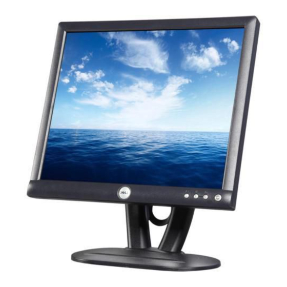
Dell E173FPc
Service Manual
17" LCD MONITOR
DELL E173FPc
THESE DOCUMENTS ARE FOR REPAIR SERVICE INFORMATION ONLY.EVERY REASONABLE EFFORT HAS
BEEN MADE TO ENSURE THE ACCURACY OF THIS MANUAL; WE CANNOT GUARANTEE THE ACCURACY
OFTHIS INFORMATION AFTER THE DATE OF PUBLICATION AND DISCLAIMS RELIABILITY FOR CHANGES,
ERRORS OR OMISSIONS.
Advertisement
Table of Contents

Related Manuals for Dell WASHING MACHINE


Summary of Contents for Dell WASHING MACHINE
-
Page 1: Service Manual
Dell E173FPc Service Manual 17” LCD MONITOR DELL E173FPc THESE DOCUMENTS ARE FOR REPAIR SERVICE INFORMATION ONLY.EVERY REASONABLE EFFORT HAS BEEN MADE TO ENSURE THE ACCURACY OF THIS MANUAL; WE CANNOT GUARANTEE THE ACCURACY OFTHIS INFORMATION AFTER THE DATE OF PUBLICATION AND DISCLAIMS RELIABILITY FOR CHANGES,... -
Page 2: Table Of Contents
Dell E173FPc Table of Contents Table of Contents ------------------------------------------------------------------------------------------------------------------- 02 Revision List --------------------------------------------------------------------------------------------------------------------03 Important Safety Notice-------------------------------------------------------------------------------------------------------------- 04 1. Monitor Specification -----------------------------------------------------------------------------------------------------------05 2. LCD Monitor Description ---------------------------------------------------------------------------------------------------------06 3. Operation Instructions ---------------------------------------------------------------------------------------------------------07 3.1 General Instructions -------------------------------------------------------------------------------------------------------07 3.2 Control Button ----------------------------------------------------------------------------------------------------------07 3.3 On Screen Menu/Display (OSD) ---------------------------------------------------------------------------------------08 3.4 Adjusting The Picture ------------------------------------------------------------------------------------------------------09... -
Page 3: Revision List
Dell E173FPc Revision List Revision Date Revision History TPV model Jun.-06-05 Initial release T782KGLHK8DMN Aug-26-2005 Change the panel type (from LPL to Hydis panel) T780KKLHK8DMN Aug-30-2005 Change the panel type (from Hydis to CPT panel) T780KCLHK8DMN Add “Important Safety Notice”... -
Page 4: Important Safety Notice
REFER TO BACK COVER FOR IMPORTANT SAFETY GUIDELINGS Important Safety Notice Proper service and repair is important to the safe, reliable operation of all Dell Company** Equipment. The service procedures recommended by Dell and described in this service manual are effective methods of performing service operations. -
Page 5: Monitor Specification
Dell E173FPc 1. Monitor Specifications Driving system TFT Color LCD LPL:LM170E01 TLB4 Panel type Hydis:HT17E13-100 CPT: CLAA170EA 07 Size 43.27cm (17.0") LCD Panel Pixel pitch 0.264mm(H) x 0.264mm(V) LPL Panel:140˚ (H) 140˚ (V) Viewable angle Hydis panel:150˚ (H) 140˚ (V) CPT panel:140˚... -
Page 6: Lcd Monitor Description
Dell E173FPc 2. LCD Monitor Description The LCD MONITOR will contain a main board, an inverter/power board, keypad board, which house the flat panel control logic, brightness control logic and DDC. The power board will provide AC to DC Inverter voltage to drive the backlight of panel and the main board chips each voltage. -
Page 7: Operation Instructions
Dell E173FPc 3. Operation instructions 3.1 General Instructions Press the power button to turn the monitor on or off. The other control buttons are located at front panel of the monitor. By changing these settings, the picture can be adjusted to your personal preferences. -
Page 8: On Screen Menu/Display (Osd)
Dell E173FPc 3.3 On Screen Menu/Display (OSD) Direct-Access Functions Function Adjustment Method Auto adjustment Use this button to activate automatic setup and adjustment. The following dialog will appear on screen as the monitor self-adjusts to the current input: Auto Adjust In Progress... -
Page 9: Adjusting The Picture
Dell E173FPc 3.4 Adjusting the Picture 1. With the menu off, push the 'MENU' button to open the OSD system and display the main features menu. Function icons Main Menu Menu icon Sub-Menu name Resolution 2. Push the - and + buttons to move between the function icons. As you move from one icon to another, the function name is highlighted to reflect the function or group of functions (sub-menus) represented by that icon. - Page 10 Dell E173FPc Menu Name and Icon Description Sub-menus EXIT This is used to exit out of the 'Main menu'. Positioning: 'Positioning' moves the viewing area around on the monitor screen. Horizontal When making changes to either the 'Horizontal' or 'Vertical' settings, no changes will Vertical occur to the size of the viewing area;...
- Page 11 Dell E173FPc Phase If satisfactory results are not obtained using the 'Phase' adjustment, use the 'Pixel Clock' adjustment and then use 'Phase' again. NOTE: This function may change the width of the display image. Use the 'Horizontal' function of the 'Position' menu to center the display image on the screen.
- Page 12 Dell E173FPc Vertical Position - and + buttons move OSD down and up. OSD Hold Time: The OSD stays active for as long as it is in use. 'OSD Hold Time': Sets the length of time the OSD will remain active after the last time you pressed a button.
- Page 13 See Specifications for the Horizontal and Vertical frequency ranges addressable by this monitor. Recommended mode is 1280 X 1024 @ 60Hz. NOTE: The floating 'Dell - self-test Feature Check' dialog will appear on-screen if the monitor cannot sense a video signal.
-
Page 14: Input/Output Specification
Dell E173FPc 4. Input/Output Specification 4.1 Input Signal Connector PIN NO. DESCRIPTION PI N NO. DESCRIPTION Red Video +5V (From PC) Green Video Detect Pin Blue Video DDC-Serial Data DDC-Return H-Sync R-Ground V-Sync G-Ground DDC-Serial Clock B-Ground VGA Connector layout... -
Page 15: Factory Preset Display Modes
Dell E173FPc 4.2 Factory Preset Display Modes VESA MODES Horizontal Vertical Nominal Sync Nominal Sync Nominal Frequency Polarit Freq. Polarity Pixel Mode Resolution Total +/- 0.5kHz +/- 1 Hz Clock (MHz) 640x480@60Hz 800 x 525 31.469 59.940 25.175 640x480@75Hz 840 x 500 37.500... -
Page 16: Panel Specification
Dell E173FPc 4.4 Panel Specification 4.4.1 Display Characteristics For LPL panel For Hydis panel... - Page 17 Dell E173FPc Display Characteristics For CPT panel...
- Page 18 Dell E173FPc 4.4.2 Optical Characteristics For LPL panel The optical characteristics are measured under stable conditions as follows: Measuring surrounding: Ta=25ºC ,Vcc=5.0V,Fv=60Hz,IBL=6.5mArms...
- Page 19 Dell E173FPc For Hydis panel...
- Page 20 Dell E173FPc For CPT panel...
-
Page 21: Block Diagram
Dell E173FPc 5. Block Diagram 5.1 Exploded View... -
Page 22: Software Flow Chart
Dell E173FPc 5.2 Software Flow Chart... - Page 23 Dell E173FPc 1) MCU Initializes. 2) Is the EEprom blank? 3) Program the EEprom by default values. 4) Get the PWM value of brightness from EEprom. 5) Is the power key pressed? 6) Clear all global flags. 7) Are the AUTO and SELECT keys pressed? 8) Enter factory mode.
-
Page 24: Electrical Block Diagram
Dell E173FPc 5.3 Electrical Block Diagram 5.3.1 Main Board... - Page 25 Dell E173FPc 5.3.2 Inverter/Power Board AC input Bridge Rectifier Transformer Rectifier CMOS EMI filter and Filter MOSFET Start Circuit Q903 R906, R907 Voltage Feedback Over Circuit Control IC Voltage Protect ON/OFF OSC and MOSFET DC Convert Output Q203 Circuit Circuit...
-
Page 26: Mechanical Instruction
Dell E173FPc 6. Mechanical Instruction Tools: 2 Power screwdrivers (φ=5mm,L=60mm); 1 small cross screwdriver; turnbuckle driver; Setting: Power screwdriver torque A=11 kgF. Cm; torque B=6 kgF. Cm Remark Rear cover Remove stand: Remove the 4 screws and remove the stand ass’y by... - Page 27 Dell E173FPc Cable hook Remove bezel: Key board Disconnect the Key board connector and remove the bezel Note: When installing monitor fixes the cable use Black Adhesive Tape and screw shield the cable hook. Remove the small shield: Remove the screws by...
- Page 28 Dell E173FPc Remove the main frame: Disconnect the back light connectors Remove the four screws and remove the main frame by manual or torque = 3kgF.Cm Lvds cable Remove the main frame and at the same time disconnect the LVDS connector...
- Page 29 Dell E173FPc Black Adhesive Tape When installing monitor. Fix the LVDS by Black Adhesive Tape. 10mm should be kept between the tape and the connect end. Power board Mylar Remove the Power board and main board: Main board Remove the eight screws by...
- Page 30 Dell E173FPc The end The angle between CCFL line and vertical direction should be 30-40 degree.
-
Page 31: Schematic Diagram
Dell E173FPc 7. Schematic Diagram 7.1 Main Board R128 1/16W R129 1/16W PC5V CN100 FB101 1/16W R101 C104 0.047uF RED+ gndR 1/16W DAT_DDC FB102 1/16W R104 C106 0.047uF GREEN+2 gndG 1/16W FB103 1/16W R105 C108 0.047uF... - Page 32 Dell E173FPc 3.3V_DVDD 1.8V_DVDD +3.3V_VDD +1.8V_VDD 3.3V_PVDD 3.3V_DVDD 1.8V_DVDD 139m A 58.27m A 3.3V_AVDD U102 L102 C130 C131 C132 C133 C134 C135 L101 C123 C124 C125 C126 C127 C128 120 OHM 3.3V_LAVDD 3.3V_DVDD 120 OHM C129 0.1uF/16V 0.1uF/16V 0.1uF/16V 0.1uF/16V 0.1uF/16V...
- Page 33 Dell E173FPc Q102 PMBS3904 R154 LED_O RP103 LED_G Q101 LED_O LED_G 4.7K 1/16W PMBS3904 R155 4.7K 1/16W 4.7K 1/16W CN101 LED_GREEN LED_ORANGE KEY _MENU ENTER R157 1/16W KEY _MENU To k e yboard KEY _RIGHT...
-
Page 34: Panel Interface
Dell E173FPc LVDS_O[0..9] LVDS_O0 CN103 LVDS_O1 LVDS_O2 LVDS_O3 LVDS_O0 RXO0- RXO0+ LVDS_O1 LVDS_O4 LVDS_O2 RXO1- RXO1+ LVDS_O3 LVDS_O5 LVDS_O4 RXO2- RXO2+ LVDS_O5 LVDS_O6 LVDS_O6 RXOC- RXOC+ LVDS_O7 LVDS_O7 LVDS_O8 RXO3- RXO3+ LVDS_O9 LVDS_O8 LVDS_E0 RXE0- RXE0+ LVDS_E1 LVDS_O9 LVDS_E2 RXE1-... - Page 35 Dell E173FPc CN104 BLON/OFF R162 4.7K 1/16W PBIAS DIMMING +3.3V_VDD FB105 TO263 C163 U105 147m A 0.1uF/16V C164 AIC1084-33M CONN C162 0.1uF/16V VOUT 100uF/16V D113 SR24 C165 C167 C168 C166 R164 47uF/16V 0.1uF/16V 0.1uF/16V 47uF/16V 1/16W R165 BRIGHTNESS ...
-
Page 36: Pwpc Board
Dell E173FPc 7.2 PWPC Board... - Page 37 Dell E173FPc...
-
Page 38: Pcb Layout
Dell E173FPc 8. PCB Layout 8.1 Main Board... - Page 39 Dell E173FPc...
- Page 40 Dell E173FPc...
-
Page 41: Pwpc Board
Dell E173FPc 8.2 PWPC Board... - Page 42 Dell E173FPc...
- Page 43 Dell E173FPc...
-
Page 44: Kepc Board
Dell E173FPc 8.3 KEPC Board 9. Maintainability 9.1 Equipments and Tools Requirement 1.Voltage meter 2.Oscilloscope 3.Pattern Generator 4.LCD Color Analyzer 5.Service Manual 6.User Manual... -
Page 45: Trouble Shooting
Dell E173FPc 9.2 Trouble shooting 9.2.1 Main Board No Screen Measured CN104 pin1 = 3.3 V? Check Power board; is there DC level output? Check U105 pin2=3.3V, U106 pin2=1.8V? Measured CN104 pin 2= 5V? Is there any shortage or cold solder? - Page 46 Dell E173FPc Panel Power Circuit Check the PPWR panel power relative circuit, Check C158 should have response from 0V to 5V when we switch the Q104, Q105, and check if the soldering for power switch from on to off them is well Replace panel Replace Q104,Q105...
- Page 47 Dell E173FPc 9.2.2 Inverter/Power Board No Power Check to CON102 Pin5=12V Check Interface board Check AC line volt 110V or 220V Check AC line Check the voltage of C904(+) Check F901, bridge rectified circuit Check start voltage for the pin3 of IC901...
- Page 48 Dell E173FPc No Backlight Check C202 (+) =12V Check F201 Check ON/OFF signal Check Interface board Check U201 pin9=12V Change Q201 or Q202 Check the pin1 of U201 have saw tooth wave Change U201 Check D201 (-), D202 (-) has the output of square wave at short time.
- Page 49 Dell E173FPc 9.2.3 Key Board OSD is unstable or not working Is Keypad board connecting normally? Connect Keypad Board Is Button Switch normally? Replace Button Switch Is Keypad board normally? Replace Keypad Board Check main board...
-
Page 50: White-Balance, Luminance Adjustment
Dell E173FPc 10. White balance, Luminance adjustment Approximately 2 Hours should be allowed for warm up before proceeding White-Balance adjustment. Before started adjust white balance, please setting the Chroma-7120 MEM. Channel 3 to 6500 K colors, MEM. Channel 4 to 9300 K colors, MEM. -
Page 51: Edid Content
Dell E173FPc 11. EDID Content 112: 12. ISP (In System Program) User Manual 12.1 Connect ISP Writer preparation action Connect RXD and TXD of PC to RXD (P3.0) and TXD (P3.1) of CPU through RS-232. There are two ways to entering Reboot Mode. The settings for Reboot Mode is as follow Both P2.6 P2.7 are LOW and RESET pin is HIGHT. -
Page 52: To Use Isp Writer
Dell E173FPc 12.2 To Use ISP WRITER ( Note: Take E153FP ISP for example Press the “–“ key at front bezel and plug the AC power cord in, then the MCU enter ISP mode; a. You will enter the window as follow after executing the ispwriter.exe file. - Page 53 Dell E173FPc b. Click the “Select Chip” button, and choose the type you are going to program.
- Page 54 Dell E173FPc c. Click the “Select Bank0” button and selecting a file which a binary Format required.
- Page 55 Dell E173FPc d. Select the communication Setting: Port Name e. Click the “ConNect” button.
-
Page 56: Executing Isp
Dell E173FPc f. Click “Program all” to start programming. 12.3. Executing ISP a. “Program All” button that will execute erase and program and verify. Then you can get the window as follow, and click “OK” to complete ISP process. b. Complete the ISP process, click“exit LD”button to reset monitor. -
Page 57: Check List
Dell E173FPc 13. Check List 13.1 After replacing LCD Main board and panel, Check if white-balance is within the Specs, then re-writing DDC is necessary. The white-balance value for each common color temperature: 9300 parameter is x=283±28, y=297±28, Y = 180 ±10 cd/m 6500 parameter is x =313±28, y=329±28, Y = 180 ±10 cd/m... - Page 58 Dell E173FPc (Connection for VGA) (Connection for DVI) 2. Seek the document with the expanded name of .BAT in DDC file of this model. It appears the indication of “Input Serial No.:"after dual-click the document to be ready for DDC-writing.
-
Page 59: Bom List
POWER BUTTON 33G4670 GV T KEY PAD 34G1367AY2 T BEZEL 34G1368 Y2 T REAR COVER 40G 190700 2B ID LABEL 40G 459700 1B6444 DELL S/N LABEL 40G 58162435A LABEL 40G 581700 3A6813 CARTON LABEL 41G7800700 2A 44G3231 9 A 44G3748 1... - Page 60 Dell E173FPc 44G3748 2 44G3748700 1A CARTON 45G 88607DE6 PE BAG FOR MONITOR 1185 4 type for dell 1186 SMALL TAPE 52G6020 2DE4 FILM PROTECT 52G6022 1500 SMALL TAPE 70G1700700 1C CD MANUAL 85G 672 1 SHIELD 85G 673 1...
- Page 61 Dell E173FPc U102 56L 562 58 GMZAN3/SL (AC) U101 56L1125137LD3 W78E65P-40 BY WINBOND Q101 57G 417 4 PMBS3904/PHILIPS-SMT(04 Q102 57G 417 4 PMBS3904/PHILIPS-SMT(04 Q105 57G 417 4 PMBS3904/PHILIPS-SMT(04 Q104 57G 763 1A AP2305N RP103 61L 125472 8 CHIP AR 8P4R 4.7K OHM+-...
- Page 62 Dell E173FPc R133 61L0603472 RST SM 0603 RC0603 4K7 R134 61L0603472 RST SM 0603 RC0603 4K7 R135 61L0603472 RST SM 0603 RC0603 4K7 R143 61L0603472 RST SM 0603 RC0603 4K7 R144 61L0603472 RST SM 0603 RC0603 4K7 R147 61L0603472 RST SM 0603 RC0603 4K7...
- Page 63 Dell E173FPc C163 65G0603104 12 CER2 0603 X7R 16V 100N C164 65G0603104 12 CER2 0603 X7R 16V 100N C167 65G0603104 12 CER2 0603 X7R 16V 100N C168 65G0603104 12 CER2 0603 X7R 16V 100N C173 65G0603104 12 CER2 0603 X7R 16V 100N...
- Page 64 Dell E173FPc CN101 95G8014 8 10 WIRE HARNESS 715L1153 1A CON201 33G8021 2D AC CONN.2P R/A 87210-0236 CON202 33G8021 2D AC CONN.2P R/A 87210-0236 CON203 33G8021 2D AC CONN.2P R/A 87210-0236 CON204 33G8021 2D AC CONN.2P R/A 87210-0236 CN901 33G8029 4A...
- Page 65 Dell E173FPc Q207 57G 417 6 PMBS3906/PHILIPS-SMT(06 Q208 57G 417 6 PMBS3906/PHILIPS-SMT(06 Q202 57G 760 4B PDTA144WK SOT346 Q201 57G 760 5B PDTC144WK SOT346 Q203 57G 763 3 AO4411 SO-8 Q204 57G 763 3 AO4411 SO-8 R204 61L0603103 RST SM 0603 RC0603 10K...
- Page 66 Dell E173FPc C230 65G0805102 32 CHIP 1000P 50VX7R 0805 C231 65G0805102 32 CHIP 1000P 50VX7R 0805 C910 65G0805102 32 CHIP 1000P 50VX7R 0805 C930 65G0805102 32 CHIP 1000P 50VX7R 0805 C931 65G0805102 32 CHIP 1000P 50VX7R 0805 C202 65G0805104 22 0.1UF +-10% 25V X7R 080...
- Page 67 Dell E173FPc R226 61G 17210252T 1K OHM 5% 1/4W R227 61G 17210252T 1K OHM 5% 1/4W R228 61G 17210252T 1K OHM 5% 1/4W R229 61G 17210252T 1K OHM 5% 1/4W R230 61G 17210252T 1K OHM 5% 1/4W R231 61G 17210252T...
- Page 68 Dell E173FPc Q903 57G 667 22 FQPF8N80C 90G6064 1 HEAT SINK M1G1730 8128 SCREW M3x8 R917 61G 2J39858F 0.390OHM 5% 2W 96G 29 6 SHRINK TUBE UL/CSA 90G6064 1 HEAT SINK D911 93G 60217 FMB-29L D910 93G 60239 FME-210B T0-220...
-
Page 69: Definition Of Pixel Defects
Dell E173FPc 15. Definition Of Pixel Defects 15.1 LM170E01 15.1.1 Dot Defect 15.1.1.1 Bright Dot Dots (sub-pixels), which appeared brightly in the screen when the LCM displayed with dark pattern. - R,G or B 1 dot --------------------------------- 0 Max - Adjacent 2 dots -------------------------------- 0 Max... -
Page 70: Ht17E13-100
Dell E173FPc 15.2 HT17E13-100... -
Page 71: Claa170Ea
Dell E173FPc 15.3 CLAA170EA 07... - Page 72 Dell E173FPc...
Need help?
Do you have a question about the WASHING MACHINE and is the answer not in the manual?
Questions and answers