Table of Contents
Advertisement
53DS---900--- --- ---117 (115 v)
53DS---900--- --- ---118 (230 v)
NOTE: Read and become familiar with these instructions before
beginning installation.
SAFETY CONSIDERATIONS
Improper
installation,
adjustment,
maintenance, or use can cause explosion, fire, electrical shock, or
other conditions which may cause death, personal injury, or
property damage. Consult a qualified installer, service agency, or
your distributor or branch for information or assistance. The
qualified installer or agency must use factory- -authorized kits or
accessories when modifying this product. Refer to the individual
instructions packaged with the kits or accessories when installing.
Follow all safety codes. Wear safety glasses, protective clothing,
and work gloves. Use quenching cloth for brazing operations.
Have fire extinguisher available. Read these instructions
thoroughly and follow all warnings or cautions included in
literature and attached to the unit. Consult local building codes
and current editions of the National Electrical Code (NEC) NFPA
70. In Canada, refer to current editions of the Canadian electrical
code CSA 22.1.
Recognize safety information. This is the safety- -alert symbol
When you see this symbol on the unit and in instructions or
manuals, be alert to the potential for personal injury. Understand
these signal words; DANGER, WARNING, and CAUTION.
These words are used with the safety- -alert symbol. DANGER
identifies the most serious hazards which will result in severe
personal injury or death. WARNING signifies hazards which
could result in personal injury or death. CAUTION is used to
identify unsafe practices which would result in minor personal
injury or product and property damage. NOTE is used to
highlight suggestions which will result in enhanced installation,
reliability, or operation.
CAUTION
!
UNIT OPERATION HAZARD
Failure to follow this caution may result in unit failure
and/or damage.
Always follow instructions properly.
Installation Instructions
alteration,
service,
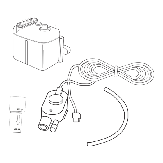
Accessory Condensate Pump
Cooling Only and Heat Pump High Wall Units
16' Transparent
Suction Discharge Tubing
Detection Unit
Mounting Bracket
Adhesive
Mounting Bracket
Fig. 1 --- Accessory Condensate Pump Kit
! !
Table 1—Accessory Condensate Pump Kit Contents
16--- ft Transparent Suction/Discharge Tubing
Condensate Pump Assembly
Low--- Voltage Power Cord
Transparent Detection Unit Vent Tubing
Power Cable
Wire Ties
Wall Mount Bracket
Adhesive
Detection Unit Mounting Bracket
Rubber Adapter
Detection Unit
!
ELECTRICAL SHOCK HAZARD
Failure to follow this warning could result in personal injury
or death.
Before beginning any modification or installation of this kit,
be sure the main electrical disconnect is in the OFF position.
Ensure power is disconnected to the fan coil unit. On some
systems both the fan coil and the outdoor unit may be on the
same disconnect. Tag the disconnect switch with a suitable
warning label. There may be more than one disconnect.
for Ductless Split System
(Size 009---036)
Condensate Pump
Assembly
Low Voltage
Power Cord
Rubber
Detection Unit
Transparent
Adapter
Detection
Unit Vent Tubing
Wire Ties (6)
Power Cable
ITEM
WARNING
A12227
QTY
1
1
1
1
1
6
1
1
1
1
1
Advertisement
Table of Contents

Summary of Contents for Dynamic 53DS---900--- --- ---117
-
Page 1: Installation Instructions
53DS---900--- --- ---117 (115 v) Accessory Condensate Pump 53DS---900--- --- ---118 (230 v) for Ductless Split System Cooling Only and Heat Pump High Wall Units (Size 009---036) Installation Instructions NOTE: Read and become familiar with these instructions before Condensate Pump 16’... - Page 2 GENERAL Table 2—Accessory Package Usage ACCESSORY MODEL NUMBER Use the two- -part accessory kit (condensate pump and detection 53DS--- 900--- --- --- 11 53DS--- 900--- --- --- 11 unit) with high wall fan coils. The pump operates whenever the BASE UNIT condensate level in the detection unit is high enough to cause the (115 ---1 ---60) (208/230 ---1 ---60)
- Page 3 5. Connect one end of the low voltage power cord to the tele- 10. Attach the remaining transparent tubing to the discharge phone jack socket in the detection unit and route the cord side of the pump. Keep the pipe vertical for at least 4 or 5 inches and do not exceed the 33 ft (10 m) limit or the and transparent drain tubing through the knockout on the value shown in (B) of Table 3 and Table 4.
- Page 4 Table 3—True Flow Rates (Gallons / Hr) 53DS--- 900--- --- --- 117, 118 Condensate Pump Flow Rates Total tube length, 1/4ä flexible hose (C) Refer to Fig. 2 for (A), (B), (C) Suction Head (A) Discharge Head (B) Table 4—True Flow Rates (Liters / Hr) 53DS--- 900--- --- --- 117, 118 Condensate Pump Flow Rates Total tube length, 1/4ä...
- Page 5 POWER AND ALARM CIRCUIT CONNECTING DISCHARGE WIRES TUBING DETECTION UNIT VENT TUBING LOW VOLT POWER CORD FAN COIL CONDENSATE DRAIN LINE COMDENSATE PUMP ASSEMBLY RUBBER ADAPTER SUCTION TUBING DETECTION UNIT DETECTION MOUNTING BRACKET UNIT A12229 Fig. 6 --- Rear of High Wall Unit with Mounted Condensate Pump PUMP DISCHARGE LINE (PROVIDED) (5) WIRES...
- Page 6 115-1-60 POWER REQUIRED FOR PUMP PUMP ALARM BREAKS SIGNAL 115-1-60 POWER SUPPLY (from outdoor or dedicated source) optional A12393 Fig. 8 --- 009, 012 (115- -1- -60) WIRING SCHEMATIC 115-1-60 POWER REQUIRED FOR PUMP PUMP ALARM BREAKS SIGNAL A12136 Fig. 9 --- (208/230- -1- -60) WIRING SCHEMATIC...
-
Page 7: Main Power Supply
PUMP POWERED FROM OUTDOOR UNIT PUMP ALARM BREAKS SIGNAL PUMP 208/230-1-60 208/230-1-60 MAIN POWER SUPPLY A13106 Fig. 10 --- (208/230- -1- -60) WIRING SCHEMATIC PUMP POWERED FROM INDOOR UNIT PUMP ALARM BREAKS SIGNAL A12395 Fig. 11 --- (115- -1- -60) WIRING SCHEMATIC... - Page 8 PUMP POWERED FROM INDOOR UNIT PUMP ALARM BREAKS SIGNAL TO OUTDOOR UNIT A12396 Fig. 12 --- (208/230- -1- -60) WIRING SCHEMATIC PUMP POWERED FROM INDOOR UNIT PUMP ALARM BREAKS SIGNAL TO OUTDOOR UNIT A12430 Fig. 13 --- (208/230- -1- -60) WIRING SCHEMATIC...
- Page 9 115-1-60 DEDICATED POWER SUPPLY FOR PUMP PUMP ALARM BREAKS SIGNAL 115-1-60 Dedicated Power Supply Indoor Unit Terminal Block Pump 115-1-60 Legend Field Power Wiring Interconnecting Wiring Pump Wiring Field Splice Connection Field Power Wiring 208/230-1-60 Outdoor Unit Terminal Block A13107 Fig.
- Page 10 A13098 Fig. 16 --- 40GVC 9k, 12k (115- -1- -60) WIRING SCHEMATIC A13099 Fig. 17 --- 40GVQ 9k, 12k (115- -1- -60) WIRING SCHEMATIC A13100 Fig. 18 --- 40GVC/Q 12k (208/230- -1- -60) WIRING SCHEMATIC...
- Page 11 A13101 Fig. 19 --- 40GVC/Q 18k, 24k, 30k, 36k (208/230- -1- -60) WIRING SCHEMATIC A13102 Fig. 20 --- 40GVM 9k, 12k, 18k (208/230- -1- -60) WIRING SCHEMATIC...
-
Page 12: Cleaning And Maintenance
CLEANING AND MAINTENANCE At the beginning of each season clean the detection unit. 1. Disconnect tubing and low voltage power cord from the WARNING detection unit and slide unit out of mounting bracket 2. Remove the top of the detection unit and take out the float. ELECTRICAL SHOCK HAZARD 3.
Need help?
Do you have a question about the 53DS---900--- --- ---117 and is the answer not in the manual?
Questions and answers