Table of Contents
Advertisement
Quick Links
UHF FM TRANSCEIVER
TK-3102G
SERVICE MANUAL
GENERAL .....................................................2
SYSTEM SET-UP .........................................2
REALIGNMENT ...........................................3
DISASSEMBLY FOR REPAIR ......................5
CIRCUIT DESCRIPTION ..............................6
SEMICONDUCTOR DATA .........................10
COMPONENTS DESCRIPTION .................11
PARTS LIST ...............................................12
EXPLODED VIEW ......................................19
PACKING ....................................................20
ADJUSTMENT ..........................................21
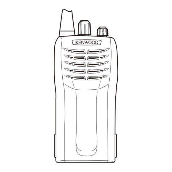
Knob (CH)
(K29-5278-03)
Whip antenna
(T90-1039-25)
CONTENTS
© 2008-8 PRINTED IN JA PAN
B51-8842-00 ( N ) 554
Knob (VOL)
(K29-5255-03)
Plastic cabinet assy
(A02-4049-03)
TX-RX UNIT (X57-6030-XX) ................26
SCHEMATIC DIAGRAM ............................30
BLOCK DIAGRAM .....................................34
LEVEL DIAGRAM ......................................36
KNB-14 (Ni-Cd BATTERY) ....................37
KNB-15A (Ni-Cd BATTERY) .................37
KNB-20N (Ni-MH BATTERY) ...............37
SPECIFICATIONS ...................BACK COVER
Advertisement
Table of Contents

Related Manuals for Kenwood TK-3102G


Summary of Contents for Kenwood TK-3102G
-
Page 1: Table Of Contents
UHF FM TRANSCEIVER TK-3102G SERVICE MANUAL © 2008-8 PRINTED IN JA PAN B51-8842-00 ( N ) 554 Knob (CH) (K29-5278-03) Whip antenna (T90-1039-25) Knob (VOL) (K29-5255-03) Plastic cabinet assy (A02-4049-03) CONTENTS GENERAL .............2 PC BOARD SYSTEM SET-UP .........2 TX-RX UNIT (X57-6030-XX) ....26 REALIGNMENT ...........3... -
Page 2: General
Kenwood reserves the right to make changes to any wise, for any purpose without the prior written permission products herein at any time for improvement purposes. -
Page 3: Realignment
TK-3102G REALIGNMENT 1. Modes 4. PC Mode 4-1. Preface User mode The transceiver is programmed by using a personal com- PC mode Data programming mode puter, a programming interface (KPG-22/22A), USB adapter (KCT-53U) and programming software (KPG-55D (ver.4.00 or PC test mode PC tuning mode later)). - Page 4 TK-3102G REALIGNMENT 4-5. Programming Software Description 4-6. Programming with PC The KPG-55D (ver.4.00 or later) is the programming If data is transferred to the transceiver from a PC with software for the transceiver supplied on a CD-ROM. This the KPG-55D (ver.4.00 or later), the data for each set can be software runs under Windows 2000, XP or Vista (32-bit) on modifi...
-
Page 5: Disassembly For Repair
TK-3102G DISASSEMBLY FOR REPAIR ■ Removing the case assembly from the chassis ■ Removing the TX-RX unit from the chassis 1. Remove the two knobs q, cushion w and three round 1. Remove the eleven screws u. nuts e. 2. Remove the VOL/CH FPC from the TX-RX unit connector 2. -
Page 6: Circuit Description
TK-3102G CIRCUIT DESCRIPTION The PLL circuit in the transmitter generates the neces- 1. Frequency Confi guration sary frequencies. Fig. 1 shows the frequencies. The receiver utilizes double conversion. The first IF is 38.85MHz and the second IF is 450kHz. The fi rst local oscil- lator signal is supplied from the PLL circuit. - Page 7 TK-3102G CIRCUIT DESCRIPTION XF201:L71-0522-05 CF200:L72-0958-05 Item Rating Item Rating Nominal center frequency 38.850MHz Nominal center frequency 450kHz Pass band width ±5.0kHz or more at 3dB 6dB band width ±6.0kHz or more 40dB stop band width ±20.0kHz or less 50dB band width ±12.5kHz or less...
- Page 8 TK-3102G CIRCUIT DESCRIPTION 2) VCO D4 in transmit mode and D1 and D3 in receive mode). The T/R pin is set high in receive mode causing Q5 and Q7 to The operating frequency is generated by Q4 in transmit turn Q4 off, and turn Q3 on . The T/R pin is set low in trans- mode and Q3 in receive mode.
-
Page 9: Power Supply
TK-3102G CIRCUIT DESCRIPTION 3) VCO and RF Amplifi er 4) ANT Switch and LPF The transmit signal obtained from the VCO buffer ampli- The RF amplifi er output signal is passed through a low- fier Q100, is amplified by Q101 and Q102. This amplified pass fi... -
Page 10: Semiconductor Data
TK-3102G SEMICONDUCTOR DATA Microprocessor: 38268MCA060GU (TX-RX unit IC403) Pin No. Port Name Function Pin No. Port Name Function VC1,VC2 Control of power supply (5M) for everything except the microprocessor and EEPROM QT/DQT external circuit center point L : Power supply ON... -
Page 11: Components Description
TK-3102G COMPONENTS DESCRIPTION TX-RX unit (X57-6030-XX) Ref. No. Part Name Description Ref. No. Part Name Description Phase locked loop system Q501,502 Transistor Active fi lter IC100 Automatic power control Q503 Transistor MIC mute/ AGC IC200 IF system Q504 Transistor DC switch... -
Page 12: Parts List
TK-3102G PARTS LIST 2 2 0 CC45 Color* 010 = 1pF 0 = 22pF 1 = Type ... ceramic, electrolytic, etc. 4 = Voltage rating 100 = 10pF 2 = Shape ... round, square, etc. 5 = Value 101 = 100pF Multiplier 3 = Temp. - Page 13 Les articles non mentionnes dans le Parts No. ne sont pas fournis. Y : AAFES (Europe) X : Australia M : Oth er Areas Teile ohne Parts No. werden nicht geliefert. TK-3102G (Y50-6420-XX) TX-RX UNIT (X57-6030-XX) Desti- Desti- Ref. No.
- Page 14 TK-3102G PARTS LIST TX-RX UNIT (X57-6030-XX) Desti- Desti- Ref. No. Ad dress Parts No. Description Ref. No. Ad dress Parts No. Description parts nation parts nation CC73GCH1H010B CHIP C 1.0PF C202 CC73GCH1H270J CHIP C 27PF CK73GB1H471K CHIP C 470PF C203...
- Page 15 TK-3102G PARTS LIST TX-RX UNIT (X57-6030-XX) Desti- Desti- Ref. No. Ad dress Parts No. Description Ref. No. Ad dress Parts No. Description parts nation parts nation C304 CS77AA0J100M CHIP TNTL 10UF 6.3WV C514 CK73GB1C473K CHIP C 0.047UF C305 CK73GB1H103J CHIP C 0.010UF...
- Page 16 TK-3102G PARTS LIST TX-RX UNIT (X57-6030-XX) Desti- Desti- Ref. No. Ad dress Parts No. Description Ref. No. Ad dress Parts No. Description parts nation parts nation L106 L34-4551-05 AIR-CORE COIL RK73GB2A471J CHIP R 1/10W K2,M2 L107 L92-0149-05 CHIP FERRITE RK73GB2A220J...
- Page 17 TK-3102G PARTS LIST TX-RX UNIT (X57-6030-XX) Desti- Desti- Ref. No. Ad dress Parts No. Description Ref. No. Ad dress Parts No. Description parts nation parts nation R213 RK73GB2A000J CHIP R 1/10W R333 RK73GB2A474J CHIP R 470K 1/10W R214 RK73GB2A103J CHIP R...
- Page 18 TK-3102G PARTS LIST TX-RX UNIT (X57-6030-XX) Desti- Desti- Ref. No. Ad dress Parts No. Description Ref. No. Ad dress Parts No. Description parts nation parts nation R518 RK73GB2A682J CHIP R 6.8K 1/10W 2SK508NV (K52) R519,520 RK73GB2A333J CHIP R 1/10W 2SC4228 (R44)
-
Page 19: Exploded View
TK-3102G EXPLODED VIEW TX-RX unit : N09-2438-05 : N14-0581-44 : N14-0804-24 D M2.6 x 6 : N30-2606-48 M2 x 3 : N79-2030-48 M2 x 5 : N83-2005-48 Parts with the exploded numbers larger than 700 are not supplied. -
Page 20: Packing
TK-3102G PACKING Instruction manual (B62-2103-00) 59 Charger 56 AC adapter (AC 120V) (W08-0598-15) (W08-0479-25):K,K2 58 AC adapter (AC 230V) 30 Protection bag (W08-0558-35):M,M2 (H25-0085-04) 54 Whip antenna (T90-1039-25) 47 Screw set (N99-0396-15) Cap (SP/MIC) (B09-0351-03) 35 SP/MIC holder 60 Battery assy... -
Page 21: Adjustment
TK-3102G ADJUSTMENT Test Equipment Required for Alignment Test Equipment Major Specifi cations Frequency Range 450 to 490MHz 1. Standard Signal Generator Modulation Frequency modulation and external modulation (SSG) Output –127dBm/0.1µV to greater than –47dBm/1mV Input Impedance 50Ω 2. Power Meter... - Page 22 TK-3102G ADJUSTMENT Controls Preparations for tuning the transceiver Before attempting to tune the transceiver, connect the unit to a suitable power supply. Channel selector Whenever the transmitter is tuned, the unit must be con- Antenna nected to a suitable dummy load (i.e. power meter).
- Page 23 TK-3102G ADJUSTMENT Common Section Measurement Adjustment Item Condition Specifi cations / Remarks Test- Unit Terminal Unit Parts Method equipment 1. Setting 1) BATT terminal voltage: 7.5V 2) SSG standard modulation [Wide] MOD: 1kHz,DEV: 3kHz [Narrow] MOD: 1kHz,DEV: 1.5kHz 2. VCO lock...
- Page 24 TK-3102G ADJUSTMENT Measurement Adjustment Item Condition Specifi cations / Remarks Test- Unit Terminal Unit Parts Method equipment 5. MIC 1) TEST CH: Center Power TX-RX Check ±2.2kHz~3.8kHz Sensitivity AG: 1kHz/12mV meter SP/MIC PTT: ON Deviation connec- [Wide] meter Oscillo- scope...
- Page 25 TK-3102G ADJUSTMENT Receiver Section Measurement Adjustment Item Condition Specifi cations / Remarks Test- Unit Terminal Unit Parts Method equipment 1. BPF wave 1) TEST CH: Center Spectrum TX-RX TX-RX TC201 Adjust the waveform adjust Spectrum analyzer setting analyzer TC202 as shown in Fig.1.
-
Page 26: Pc Board
TK-3102G PC BOARD TX-RX UNIT (X57-6030-XX) -10 : K,M -11 : K2,M2 Component side view (J79-0171-09) R341 Q306 C332 C330 R332 C336 C262 C411 R509 Q305 IC302 R504 R408 IC402 R404 R501 R503 R327 C500 IC400 R418 R500 C400 C415... - Page 27 TK-3102G PC BOARD TX-RX UNIT (X57-6030-XX) -10 : K,M -11 : K2,M2 Component side view (J79-0171-09) R341 R135 R146 MIC500 C134 C132 R136 R531 Q307 IC100 Q110 C127 C115 R542 R522 R523 R520 C517 D400 C420 D401 R415 R417 R414...
- Page 28 TK-3102G PC BOARD TX-RX UNIT (X57-6030-XX) -10 : K,M -11 : K2,M2 Foil side view (J79-0171-09) S402 S403 MONI C532 L210 R227 C234 C155 C147 C236 R229 L211 C233 L110 C255 C263 R232 R231 L208 L113 C138 C254 R123 D204...
- Page 29 TK-3102G PC BOARD TX-RX UNIT (X57-6030-XX) -10 : K,M -11 : K2,M2 Foil side view (J79-0171-09) C228 C213 R200 C258 R208 R210 L203 L206 Q200 C223 C214 Q201 C231 R219 R228 R207 C227 R220 D300 C210 D203 R204 R229 C204...
-
Page 30: Schematic Diagram
TK-3102G SCHEMATIC DIAGRAM TX-RX UNIT(X57-6030-XX) RF AMP 2SC5108(Y)F 470p 3p(B) L77-1877-15 T:4.9V 12.8MHz T:2.4V R:4.9V R:2.4V 4.7u6.3 0.1u UNLOCK DETECT 100k 2.2k MA2S111-F 8.2u T:0V R:4.9V R:5.0V 560n 1k*4 330k 0.01u 220n 220n TRIPLER MB15A02PFV2E1 2SC4649(N,P) R:0.7V PHASE LOCKED LOOP SYSTEM... - Page 31 TK-3102G SCHEMATIC DIAGRAM TX-RX UNIT(X57-6030-XX) VCO TX 2SC4228(R44) 3.3u MA2S376 RF AMP T:1.4V T:3.8V RF BUFFER AMP R:0V Q100 R:3.8V 2SC5108(Y)F C105 2SC5108(Y)F C100 0.5p(B) T:1.1V R:1.3V DC SW D2,4 2SJ243-A FREQ. CONTROL TX MODULATION DC SW UMC4N D1,3 FREQ.
- Page 32 TK-3102G SCHEMATIC DIAGRAM TX-RX UNIT(X57-6030-XX) TX DRIVE T:7.1V Q105 L119 2SK2596-E C119 R127 T:4.8V T:0.5V 2.2n C108 R112 C111 R115 C114 R120 1000p T:0.9V 1.5k 470p RF SW D100 C106 T:0.5V HSC277 470p Q102 Q101 2SC4988-E 2SC5108(Y)F TX DRIVE TX PRE-DRIVE T:1.0V...
- Page 33 TK-3102G SCHEMATIC DIAGRAM TX-RX UNIT(X57-6030-XX) C149 C151 C154 ANTENNA SW TX FINAL 1p(B) 1.5p(B) 1p(B) T:7.3V D101 Q107 C138 HVU131-E 2SK2595-E R123 C145 L112 L113 L114 100p 470p T:7.3V T:7.4V R147 D102,103 ANTENNA SW R144 2.2k R136 DC SW 150k(D)
-
Page 34: Block Diagram
TK-3102G BLOCK DIAGRAM MA360 (K,M) 2SC5108 1SV214-F (Y)F (K2,M2) 2SC4228 2SC5108 2SC5 (R44) (Y)F MB15A02PFV2E1 Q5,Q7 2SJ243 2SK508NV (K52) L77-1877 UMC4N Q403 144EE IC403 38268MCA060GU IC200 TA31136FNG 2SC4649 (N,P) IC401 CAT24WC08 JI18 IC402 NJM2904V-ZB R3111N 451C-F D300 IC404 DA221 XC6201... - Page 35 TK-3102G BLOCK DIAGRAM Q100 Q101 Q102 Q105 Q107 D101 2SC5108 2SC5108 2SC4988 2SK2596 2SK2595 HVU131 (Y)F (Y)F Q8,D6 2SC4617 MA2S111 IC100 NJM2904 V-ZB Q104 Q103 UFMMT717 2SK1824 Q106 2SK1824 Q108 114EE XF201 Q201 Q202 Q203 2SC4649 3SK318 3SK318 (N,P) L208,L209,...
-
Page 36: Level Diagram
TK-3102G LEVEL DIAGRAM... -
Page 37: Optional Accessories
TK-3102G OPTIONAL ACCESSORIES KNB-14 (Ni-Cd BATTERY) ■ External View ■ Schematic Diagram ■ Specifi cations Discharge pin side Voltage : 7.2V (1.2V x 6) Capacity : 600mAh Dimensions : 60.8W x 110.8H x 17.3D (mm) Breaker Breaker (projections included) (70±5 °... -
Page 38: Specifications
Unit 3712-3724, Level 37, Tower one Metroplaza, 223 Hing Fong Road, Bp 58416 Villepinte, 95944 Roissy Ch De Gaulle Cedex Kwai Fong, N.T., Hong Kong KENWOOD House, Dwight Road, Watford, Herts., 1 Ang Mo Kio Street 63, Singapore 569110 WD18 9EB United Kingdom... -
Page 39: Pc Board Tx-Rx Unit (X57-6030-Xx)
TK-3102G TK-3102G PC BOARD PC BOARD TX-RX UNIT (X57-6030-XX) -10 : K,M -11 : K2,M2 TX-RX UNIT (X57-6030-XX) -10 : K,M -11 : K2,M2 Component side view (J79-0171-09) Component side view (J79-0171-09) R341 Q306 C332 R135 R146 MIC500 C134 C132... - Page 40 TK-3102G TK-3102G PC BOARD PC BOARD TX-RX UNIT (X57-6030-XX) -10 : K,M -11 : K2,M2 TX-RX UNIT (X57-6030-XX) -10 : K,M -11 : K2,M2 Foil side view (J79-0171-09) Foil side view (J79-0171-09) S402 S403 MONI C228 C213 C258 R200 R208...
- Page 41 TX-RX UNIT(X57-6030-XX) RF AMP C149 C151 C154 2SC5108(Y)F TX FINAL ANTENNA SW 1p(B) 1.5p(B) 1p(B) 470p T:7.3V 3p(B) Q107 D101 TX DRIVE T:7.1V 2SK2595-E R123 C138 HVU131-E C145 L112 L113 L114 VCO TX Q105 2SK2596-E L119 C119 R127 100p 470p T:4.8V T:0.5V L77-1877-15...
- Page 42 MA360 (K,M) 2SC5108 1SV214-F (Y)F (K2,M2) Q100 Q101 Q102 Q105 Q107 D101 2SC4228 2SC5108 2SC5108 2SC5108 2SC4988 2SK2596 2SK2595 HVU131 (R44) (Y)F (Y)F (Y)F MB15A02PFV2E1 Q8,D6 Q5,Q7 2SC4617 2SJ243 2SK508NV (K52) MA2S111 L77-1877 UMC4N IC100 NJM2904 V-ZB Q403 144EE Q104 Q103 UFMMT717 2SK1824...
Need help?
Do you have a question about the TK-3102G and is the answer not in the manual?
Questions and answers