Advertisement
WARNING
To reduce the risk of fire, burn hazard or other injury,
read the manual carefully and completely before
using your grill.
Example only: SERIAL # ________ MFG. DATE ________ PURCHASE DATE: _________
Questions, problems, missing parts? Before returning to your retailer, call our customer
service department at 1- 800-913-8999, 7 a.m. - 5 p.m., PST, Monday - Friday
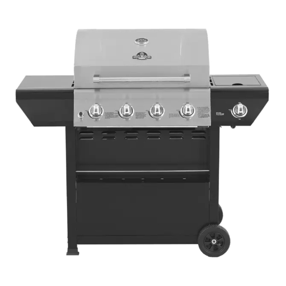
LP GAS GRILL
GRIL AU GAZ DE PÉTROLE LIQUÉFIÉ
(page 29)
PARRILLA A GAS PROPANO
(página 57)
300
400
500
600
200
100
700
800
WARNING
FOR OUTDOOR USE ONLY.
WARNING
This grill is not intended to be
installed in or on recreational
vehicles and/or boats.
ITEM / ARTICLE / ARTICULO # 0134489
MODEL / MODÈLE / MODELO # 720-0697
®
Advertisement
Table of Contents

Subscribe to Our Youtube Channel
Related Manuals for GrillMaster 134489


Summary of Contents for GrillMaster 134489
- Page 1 ITEM / ARTICLE / ARTICULO # 0134489 LP GAS GRILL GRIL AU GAZ DE PÉTROLE LIQUÉFIÉ (page 29) PARRILLA A GAS PROPANO (página 57) MODEL / MODÈLE / MODELO # 720-0697 WARNING WARNING To reduce the risk of fire, burn hazard or other injury, FOR OUTDOOR USE ONLY.
-
Page 2: Table Of Contents
TABLE OF CONTENTS Safety Information......................3 Package Contents List.......................7 Preparation ........................8 Assembly Instructions......................9 Installation Instructions ......................17 Operating Instructions......................20 Care and Maintenance ......................22 Troubleshooting .........................24 Warranty ..........................26 Replacement Parts List......................27 DANGER WARNING If you smell gas: 1. Do not store or use gasoline or other 1. -
Page 3: Safety Information
SAFETY INFORMATION WARNING Do not try lighting this appliance without first reading WARNING the “LIGHTING INSTRUCTIONS” section of this manual. WARNING – Hazards or unsafe practices which COULD result in severe personal injury or death. CAUTION CAUTION – Hazards or unsafe practices which COULD result in minor personal injury. - Page 4 WARNING WARNING Do not leave the grill unattended while cooking. Spiders and insects can nest inside the burners of the grill and disrupt gas flow. WARNING Inspect the grill at least twice a year. Failure to properly place the burner over the orifice could cause a fire to occur behind and beneath the valve panel, thereby damaging the grill and making CAUTION...
- Page 5 Do not use indoors. TESTED IN ACCORDANCE WITH ANSI Z21.58a WARNING LATEST STANDARD and CGA 1.6a-2008 Do not try lighting this appliance without first STANDARD FOR OUTDOOR COOKING GAS reading the “LIGHTING INSTRUCTIONS” section APPLIANCES. THIS GRILL IS FOR OUTDOOR USE of this manual.
- Page 6 For proper lighting and performance of the burners, keep the burner ports clean. It is necessary to clean them periodically for optimum performance. The burners will only operate in one position and must be mounted correctly for safe operation. Exercise caution when cleaning grill. To avoid steam burns, do not use a wet sponge or cloth to clean the grill while it is hot.
-
Page 7: Package Contents List
PACKAGE CONTENTS LIST A. Firebox Assembly --------1pc. B. Bottom Panel----------1pc. C. Wheel-----------------------2pcs. 4 00 D. Side Burner Shelf & Control E. Left Side Shelf & Control F. Cart Leg, Front Left--------1pc. Panel-------1pc. Panel------1pc. G. Cart Leg, Back Left--------1pc. H. Cart Frame, Top-----------2 pcs. I. -
Page 8: Preparation
V. 1.5 Volt “AA” Size Alkaline W. Grease Box ----------1pc. X. Grease Tray -------- 1pc. Battery----------1pc. Y. Diagonal Bar Barrier -----1pc. Z. Warming Rack ----------1pc. ZA. Flame Tamers-------4pcs ZB. Cooking Grids----------2pcs. HARDWARE CONTENTS - Pre-installed as noted in instructions that follow. REF# Description 5/32-in. -
Page 9: Assembly Instructions
ASSEMBLY INSTRUCTIONS Fig. 1 1. Cart Caster and Cart Assembly a) Place the Cart Caster Inset (K) into the Cart Leg, Front Left (F) and Cart Leg, Back Left (G). As shown in Fig. 1. Fig. 2 b) Loosen, but do not remove the screws that are pre-assembled on the Cart Leg, Front Left (F) and Cart Leg, Back Left (G). - Page 10 Fig. 4 2. Bottom Panel Assembly Tank Bolt a) Loosen, but do not remove the screws that are pre-assembled on the side of the Bottom Panel (B), align the holes on the Cart Leg, Front Left (F) and Cart Leg, Back Left (G), then place the Cart Legs onto the screws that were loosened in the Bottom Panel (B).
- Page 11 Fig. 7 5. Condiment Tray Assembly a) Remove the screws which are pre-assembled on the Front Panel (S),attach the condiment tray (T) to Cart Leg, Front Left (F) and Cart Leg, Front Right (I) by loosening the two screws in the each cart leg. Align the holes of the Condiment Tray (T) with the screws.
- Page 12 Fig. 10 8. Diagonal Bar Barrier Assembly Loosen but do not remove the one screw which is pre-assembled on the Bottom Panel (B). Secure solid end of the Diagonal Bar Barrier (Y) to the underside of the Front Panel (S), then secure other end of Diagonal Bar Barrier (Y) by clipping the open hole onto the screw which pre-assembled on the Bottom Panel (B).
- Page 13 Fig. 12 10. Firebox Assembly NOTE: We suggest two persons lift the firebox when assembling. Be sure to remove all packaging 3 00 2 0 0 1 0 0 7 00 material during assembly. a) Remove two screws which are pre-assembled on the Cart Leg Back Right (J) and Cart Leg Back Left (G).
- Page 14 Fig. 14 11. Side Burner Shelf Assembly Loosen but do not remove the screw which are pre-assembled on the cart leg. Remove the two screws that are attached to the Side Burner Shelf (D) frame and the two screws that are attached to the main control panel.
- Page 15 Fig. 18 14. Side Burner Installation a) From underneath the side burner remove two screws which are assembled on the bottom of the side burner shelf (D). Open side burner lid and place the Side Tube Burner (U) through the opening. Place the Side Tube Burner (U) tube over the side burner gas valve and make sure Side Burner gas valve is inserted into side burner tube.
- Page 16 Fig. 21 16. Install the Grease Tray Install the Grease Tray (X) from the rear of the grill by sliding the tray on the glides at the rear of the grill until centered under the cooking area As shown in Fig. 21. Fig.
-
Page 17: Installation Instructions
Fig. 24 19. Liquid Propane Hook-Up Attach the regulator to the propane cylinder by turning the regulator handle clockwise as shown in Fig. 24. If the outdoor cooking appliance is not in use, the gas must be turned “Closed” position at the Liquid Propane Cylinder. - Page 18 CONNECTING THE LIQUID PROPANE CYLINDER To connect the Liquid Propane Gas Supply Cylinder: a) The cylinder valve should be in the “OFF” position. If not, turn the valve clockwise until it stops. b) Make sure the cylinder valve has the proper type-1 external male thread connections per ANSI Z21.81.
- Page 19 Make a solution of one part liquid detergent and one part water. You will need a spray bottle, brush, or rag to apply the solution to the fittings. For the initial leak test, make sure the Liquid Propane Cylinder is full.
-
Page 20: Operating Instructions
It is very important to keep your appliance’s clear and away from any combustible materials. Maintain at least 24 inches of clearance from sides and back and do not use under overhead combustible construction. No overhead combustible construction OPERATING INSTRUCTIONS General Use of the Grill Each main burner is rated at 12,000 BTU/Hr. - Page 21 LIGHTING INSTRUCTIONS Before Lighting Inspect the gas supply hose prior to turning on the gas. If there is evidence of cuts, wear, or abrasion, it must be replaced prior to use. Screw the regulator (type QCC1) onto the cylinder, and leak check the hose and regulator connections before operating the grill (see the “Leak Testing”...
-
Page 22: Care And Maintenance
TO MATCH LIGHT THE GRILL If a burner will not light after several attempts using the control knobs, the burners may be lit with a match. WARNING CAUTION When lighting, keep your face and hands as far When using a match to light the grill make sure to away from the grill as possible. - Page 23 Wear a barbeque mitt to protect your hand from heat and steam. Scrub the hot cooking grates by dipping a bristled barbeque brush in tap water. Cleaning will be more difficult if the grill is allowed to cool. Grease Pan The grease pan should be emptied, wiped down and washed after each use with a mild detergent and warm water solution.
-
Page 24: Troubleshooting
Fig. 28 TROUBLESHOOTING Problems Possible Solutions Grill will not light. 1. Push and turn the knob and check for sparks. 2. If there is a spark, check to make sure gas is supplied to the burner. a. Purge the line of any trapped air. b. - Page 25 Problems Possible Solutions Burner blows out. 1. Check for any burner defects. 2. Check for proper burner installation. 3. Make certain the fuel mixture is not too lean. 4. Make sure the gas supply is sufficient. 5. See if the LP tank is empty. Low heat, LP gas.
-
Page 26: Warranty
Nexgrill Customer Relations 5270 Edison Avenue., Chino, CA 91710 All consumer returns, parts orders, general questions, and troubleshooting assistance can be acquired by calling 1-800-913-8999. GrillMaster is a trademark of Sunbeam Products, Inc. used under license. Distributed by Nexgrill Industries, Inc. -
Page 27: Replacement Parts List
REPLACEMENT PARTS LIST For replacement parts, call our customer service department at 1-800-913-8999, 7 a.m. – 5 p.m., PST, Monday – Friday. WARRANTY WARRANTY REF# DESCRIPTION QTY REF# DESCRIPTION COVERAGE COVERAGE Main Lid Cart Caster Insert 2pcs Hood Buffer B 2pcs 32Q Bottom Panel, LP Main Lid Screw 2pcs 33Q Cart Frame... - Page 28 4 00...
Need help?
Do you have a question about the 134489 and is the answer not in the manual?
Questions and answers