Advertisement
Table of Contents
- 1 Table of Contents
- 2 Safety Information
- 3 Package Contents List
- 4 Preparation
- 5 Assembly Instructions
- 6 Installation Instructions
- 7 Operating Instructions
- 8 Care and Maintenance
- 9 Troubleshooting
- 10 Limited Warranty
- 11 Warranty
- 12 Replacement Parts List
- Download this manual
See also:
Instruction and Installation Manual
WARNING
WARNING
WARNING
WARNING
To reduce the risk of fire, burn hazard or other injury,
read the manual carefully and completely before
using your grill.
19000516A0
Example only: SERIAL # ________ MFG. DATE ________ PURCHASE DATE: _________
Questions, problems,
Questions,
Questions,
Questions,
service department at 1-800-913-8999 in USA and 1-800-648-5864 in Canada, 7 a.m. - 5 p.m.,
PST, Monday – Friday.
Visit our website at: www.grillmasterbbqs.com
LP
LP
LP
LP GAS
GRIL
GRIL
GRIL
GRIL AU
(page
(page
(page 2 2 2 2 8 8 8 8 ) ) ) )
(page
PARRILLA
PARRILLA A A A A GAS
PARRILLA
PARRILLA
( ( ( ( p p p p á á á á gina
problems, missing
problems,
problems,
missing
missing
missing parts?
parts? Before returning to your retailer, call our customer
parts?
parts?
www.grillmasterbbqs.com
www.grillmasterbbqs.com
www.grillmasterbbqs.com
ITEM / ARTICLE / ARTICULO # 4PV5430000010
GAS
GAS
GRILL
GRILL
GAS GRILL
GRILL
AU
GAZ
DE
DE P P P P É É É É TROLE
AU GAZ
AU
GAZ
GAZ DE
DE
GAS
GAS
GAS PROPANO
gina
58
58) ) ) )
gina 58
gina
58
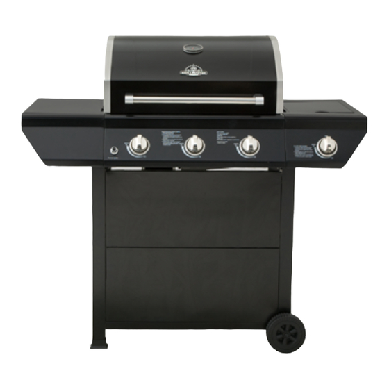
MODEL / MODÈLE / MODELO # 720-0737
3 0 0
4 0 0
5 0 0
2 0 0
6 0 0
1 0 0
7 0 0
8 0 0
WARNING
WARNING
WARNING
WARNING
FOR OUTDOOR USE ONLY.
WARNING
WARNING
WARNING
WARNING
This grill is not intended to be
installed in or on recreational
vehicles and/or boats.
TROLE
LIQU
LIQUÉ É É É FI FI FI FIÉ É É É
TROLE
TROLE LIQU
LIQU
PROPANO
PROPANO
PROPANO
®
Advertisement
Table of Contents

Related Manuals for GrillMaster 720-0737


Summary of Contents for GrillMaster 720-0737
- Page 1 ( ( ( ( p p p p á á á á gina gina 58) ) ) ) gina gina 58 MODEL / MODÈLE / MODELO # 720-0737 3 0 0 4 0 0 5 0 0 2 0 0...
-
Page 2: Table Of Contents
TABLE TABLE CONTENTS CONTENTS TABLE TABLE OF OF CONTENTS CONTENTS Safety Information..........................3 Package Contents List........................7 Preparation............................8 Assembly Instructions......................... 9 Installation Instructions........................16 Operating Instructions......................... 19 Care and Maintenance........................22 Troubleshooting............................ 23 Warranty..............................25 Replacement Parts List........................26 DANGER DANGER DANGER DANGER WARNING WARNING... -
Page 3: Safety Information
SAFETY SAFETY SAFETY SAFETY INFORMATION INFORMATION INFORMATION INFORMATION WARNING WARNING WARNING WARNING Do not try lighting this appliance without first reading WARNING WARNING WARNING WARNING the “LIGHTING INSTRUCTIONS” section of this manual. WARNING WARNING – – – – Hazards or unsafe WARNING WARNING practices which COULD result in severe... - Page 4 WARNING WARNING WARNING WARNING WARNING WARNING WARNING WARNING Do not leave the grill unattended while cooking. Spiders and insects can nest inside the burners of the grill and disrupt gas flow. WARNING WARNING WARNING WARNING Inspect the grill at least twice a year. Failure to properly place the burner over the orifice could cause a fire to occur behind and beneath the valve panel, thereby damaging the grill and making...
- Page 5 Do not use indoors. TESTED TESTED TESTED TESTED IN IN IN IN ACCORDANCE ACCORDANCE ACCORDANCE ACCORDANCE WITH WITH WITH WITH ANSI ANSI ANSI ANSI Z21.58a Z21.58a Z21.58a Z21.58a WARNING WARNING WARNING WARNING LATEST LATEST LATEST LATEST STANDARD STANDARD STANDARD STANDARD and and CGA CGA 1.6 1.6a a a a -200...
- Page 6 For proper lighting and performance of the burners, keep the burner ports clean. It is necessary to clean them periodically for optimum performance. The burners will only operate in one position and must be mounted correctly for safe operation. Exercise caution when cleaning grill. To avoid steam burns, do not use a wet sponge or cloth to clean the grill while it is hot.
-
Page 7: Package Contents List
PACKAGE PACKAGE PACKAGE PACKAGE CONTENTS CONTENTS CONTENTS CONTENTS LIST LIST LIST LIST A. Firebox Assembly-1pc. B. Bottom Panel-1pc. C. Wheel-2pcs. 3 0 0 4 0 0 5 0 0 6 0 0 2 0 0 1 0 0 8 0 0 7 0 0 D. -
Page 8: Preparation
V. 1.5 Volt “AA” Size Alkaline W. Grease Box-1pc. X. Grease Tray-1pc. Battery-1pc. Y. Diagonal Bar Barrier-1pc. Z. Side Burner Cooking Grid-1pc. HARDWARE HARDWARE CONTENTS CONTENTS CONTENTS - - - - Pre-installed Pre-installed Pre-installed noted noted noted in in in in instructions instructions instructions that... -
Page 9: Assembly Instructions
ASSEMBLY ASSEMBLY INSTRUCTIONS INSTRUCTIONS ASSEMBLY ASSEMBLY INSTRUCTIONS INSTRUCTIONS Fig. Fig. Fig. 1 1 1 1 Fig. 1. 1. 1. 1. Ca Cart rt rt rt Assembly Assembly Assembly Assembly a) Place the Cart Caster Inset (K) into the Cart Leg, Front Left (F) and Cart Leg, Back Left (G). - Page 10 Fig. Fig. Fig. Fig. 4 4 4 4 2. 2. 2. 2. Bo Bottom ttom ttom ttom Panel Panel Panel Panel Assembly Assembly Assembly Assembly a) Loosen, but do not remove the screws that are pre-assembled on the side of the Bottom Panel (B), align the holes on the Cart Leg, Front Left (F) and Cart Leg, Back Left (G), then place the Cart Legs onto the screws that were...
- Page 11 Fig. Fig. Fig. Fig. 7 7 7 7 5. 5. 5. 5. Wheel Wheel Wheel Wheel Assembly Assembly Assembly Assembly a) Remove the nuts and washers which are pre-assembled on the short axle, place the wheels (C) on the Axle attached to Cart Leg, Front Right (I) and Cart Leg, Back Right (J).
- Page 12 Fig. Fig. Fig. Fig. 10 8. 8. 8. 8. Firebox Firebox Firebox Firebox Assembly Assembly Assembly Assembly NOTE: We suggest two persons lift the firebox 3 0 0 4 0 0 5 0 0 6 0 0 2 0 0 1 0 0 8 0 0 7 0 0...
- Page 13 Fig. Fig. Fig. Fig. 12 9. 9. 9. 9. Side Side Side Side Burner Burner Burner Burner Shelf Shelf Shelf Shelf Assembly Assembly Assembly Assembly a) Loosen but do not remove the screws which is pre-assembled on the cart leg. Remove the two screws that are attached to the Side Burner Shelf (D) frame and the two screws that are attached to the main control panel.
- Page 14 Fig. Fig. Fig. Fig. 15 b) Insert Side Burner Control Knob (M) onto the valve stem and tighten it. As shown in Fig. 15. 1 1 1 1 2 2 2 2 ..Side Side Side Burner Burner Installation Installation...
- Page 15 Fig. Fig. Fig. Fig. 18 Electronic Electronic Igniter Igniter Battery Battery tallation tallation 13. Electronic Electronic Igniter Igniter Battery Battery Ins Installation tallation Unscrew the electronic igniter button 3 0 0 4 0 0 5 0 0 6 0 0 2 0 0 1 0 0 8 0 0...
-
Page 16: Installation Instructions
16. Liquid Liquid Liquid Liquid Propane Propane Propane Propane Tank Tank Tank Tank Installation Installation Installation Installation Fig. Fig. Fig. Fig. 21 From rear of grill place the liquid propane tank into the Bottom Panel (B) hole and tighten the Tank Bolt (Q) to secure. - Page 17 LIQUID LIQUID PROPANE PROPANE CYLINDER CYLINDER REQUIREMENTS REQUIREMENTS LIQUID LIQUID PROPANE PROPANE CYLINDER CYLINDER REQUIREMENTS REQUIREMENTS (20-lb (20-lb (20-lb (20-lb..Cylinder) Cylinder) Cylinder) Cylinder) A dented or rusty Liquid Propane Cylinder may be hazardous and should be checked by your supplier. Never use a cylinder with a damaged valve.
- Page 18 DISCONNECTING DISCONNECTING DISCONNECTING DISCONNECTING THE THE LIQUID LIQUID LIQUID LIQUID PROPANE PROPANE PROPANE PROPANE CYLINDER CYLINDER CYLINDER CYLINDER 1. Turn the grill burner valves “OFF” and make sure the grill is cool. 2. Turn the Liquid Propane Cylinder valve “OFF” by turning clockwise until it stops. 3.
-
Page 19: Operating Instructions
WARNING WARNING WARNING WARNING 1. Do not store spare Liquid Propane Cylinders under or near this appliance. 2. Never fill the cylinder beyond 80 percent capacity. 3. If the information above is not followed exactly, a fire, possibly causing serious injury or death, may occur. - Page 20 4. Turn the control knob(s) to the “IGNITE / HI” setting, and preheat the grill for 15 minutes. The grill lid should be closed during the pre-heat period. 5. Place the food on the grill and cook to the desired degree of preparation. If necessary, adjust the heat setting.
- Page 21 TO MATCH MATCH MATCH MATCH LIGHT LIGHT LIGHT LIGHT THE THE GRILL GRILL GRILL GRILL If a burner will not light after several attempts using the control knobs, the burners may be lit with a match. WARNING WARNING CAUTION CAUTION WARNING WARNING CAUTION...
-
Page 22: Care And Maintenance
CARE CARE CARE CARE AND AND MAINTENANCE MAINTENANCE MAINTENANCE MAINTENANCE Stainless Stainless Stainless Stainless Steel Steel Steel Steel There are many stainless steel cleaners available. Always use the mildest cleaning process first, scrubbing in the direction of the grain. Do not use steel wool as it will scratch the surface. To touch up noticeable scratches in the stainless steel, sand very lightly with dry 100 grit sand paper in the direction of the grain. -
Page 23: Troubleshooting
Check for proper burner flame characteristics. Burner flames should be blue and stable with no yellow tips, Excessive noise, or lifting as shown in Fig. 26. The following steps should be followed for correcting the flame characteristics: 1. Turn the control knobs and Liquid Propane Cylinder valves “OFF”. 2. - Page 24 Problems Problems Problems Problems Possible Possible Possible Possible Solutions Solutions Solutions Solutions Burner blows out. 1. Check for any burner defects. 2. Check for proper burner installation. 3. Make certain the fuel mixture is not too lean. 4. Make sure the gas supply is sufficient. 5.
-
Page 25: Warranty
720-0737 The manufacturer warrants to the original consumer-purchaser only that this product (Model #720-0737) shall be free from defects in workmanship and materials after correct assembly and under normal and reasonable home use for the periods indicated below beginning on the date of purchase. The manufacturer reserves the right to require photographic evidence of damage, or that defective parts be returned, postage and/or freight pre-paid by the consumer, for review and examination. -
Page 26: Replacement Parts List
REPLACEMENT REPLACEMENT PARTS PARTS LIST LIST REPLACEMENT REPLACEMENT PARTS PARTS LIST LIST For replacement parts, call our customer service department at 1-800-913-8999 in USA and 1-800-648- 5864 in Canada, 7 a.m. – 5 p.m., PST, Monday – Friday. WARRANTY WARRANTY REF# DESCRIPTION QTY REF# DESCRIPTION COVERAGE... - Page 27 3 0 0 4 0 0 5 0 0 6 0 0 2 0 0 1 0 0 8 0 0 7 0 0 50Q/A Printed in China...
Need help?
Do you have a question about the 720-0737 and is the answer not in the manual?
Questions and answers