Table of Contents
Advertisement
Advertisement
Table of Contents

Related Manuals for FLYGT FPC100

Summary of Contents for FLYGT FPC100
- Page 1 Installation and user manual for FPC100 Single pump controller...
-
Page 3: Table Of Contents
Start conditions and pause time adjustment................. 14 Window parameters......................... 15 PROTECTION AND ALARM........................19 Protection and alarm........................19 TROUBLESHOOTING.......................... 21 Troubleshooting..........................21 TECHNICAL SPECIFICATIONS......................22 Electronics............................22 EU specifications..........................22 USA specifications..........................22 Canadian specifications........................23 Part numbers............................23 Single pump controller Installation and user manual for FPC100... -
Page 4: Quick Set-Up Of Fpc100
QUICK SET-UP OF FPC100 Quick set-up of FPC100 The purpose with the quick set-up is to initiate the stop function. FPC100 stops the pump when the water level has dropped to such a low level that the pump begins to draw air (snore). -
Page 5: Safety
Áður en starfræksla hefst, gangið úr skugga um að sjálfvirkur gangsetningarbúnaður sé óvirkur, þ.e.a.s. ekki tengdur við rafmagn. Ðñéí áðü êÜèå åñãáóßá, åëÝãîôå áí ôï êéâþôéï ôïõ áõôüìáôïõ åëÝã÷ïõ Ý÷åé áðïóõíäåèåß áðü ôï ñåýìá êáé äåí ìðïñåß íá ôåèåß õðü ôÜóç. Single pump controller Installation and user manual for FPC100... -
Page 6: Unpacking, Inspection And Recycling
Keep the packing. It can be needed for return of the delivery or in case of inspection at damage. The housing of the FPC100 is made of recyclable plastic, type PC/ABS. The circuit boards contain minimal amounts of tin and lead. -
Page 7: Installation
Before installing, make sure that no voltage is applied to the equipment. Check that the rated voltage of FPC100 corresponds with the supplying line voltage. The rated voltage can be found on the rating plate on the side of the control unit. -
Page 8: Choice And Adaptation Of Current Transformer
Number of turns = 10 A/7.8 A Answer = 1 100-1000A If the rated motor current is in excess of the highest rated primary current of the available transformers (100A), proceed as follows: Single pump controller Installation and user manual for FPC100... -
Page 9: Current Transformer Connection
55 mA as possible, but should not exceed it. This in order to put the available capacity of the current input range in FPC100 to full use, hence resulting in a better functionality. The secondary current can be checked in window 61 or with an external multimeter. -
Page 10: Digital Input Connection (Dig In)
As an alternative the terminals can be used with any device using a voltage-free opening contact such as a motor protection unit. Terminal 4 is the common signal ground for terminal 5 and terminal 3. Single pump controller Installation and user manual for FPC100... -
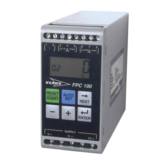
Page 11: Front Panel Layout And Function Keys
Proceeds to the next window – Decreases the displayed value For fast decrement, depress button 6 sec Increases the displayed value For fast increment, depress button 6 sec ENTER Confirms the adjustments made Single pump controller Installation and user manual for FPC100... -
Page 12: Display, Symbols And Units
Minutes Seconds Percent Note 1: When FPC100 is turned on, a self test is performed during 3 seconds and all characters and symbols on the display are shown. Note 2: During alarm the entire display is flashing. Note 3: If “oor” (out of range) is shown on the display, it means that the value is too big to be shown on the display. -
Page 13: Detailed Settings
Adjustments and settings are done in a single-level menu structure, windows 00-99. When FPC100 is turned on, press NEXT to proceed to the next window, press + or – to increase or decrease the value and press ENTER to confirm the new value in each window. - Page 14 4. Clear the present stop level by pressing AUTOSET until “SEt” is shown on the display. The stop level is hence set to 0 % since the pump is off. 5. Set window 13 to ( – ) and confirm with ENTER. FPC100 is now prepared for Auto-set at pumping without snoring.
- Page 15 4. Clear the present stop level by pressing AUTOSET until “SEt” is shown on the display. The stop level is hence set to 0 % since the pump is off. 5. Set window 13 to ( _ ) and confirm with ENTER. FPC100 is now prepared for Auto-set at snoring.
-
Page 16: Adjustment Of The Stop Level
In some applications the inflow may increase rapidly during a pause. To prevent overflow in these situations the maximum pause time can be set in accordance with the circumstances. Single pump controller Installation and user manual for FPC100... -
Page 17: Window Parameters
S. Measured power in % 0–125 % of the measuring range Measured line 0–999 V voltage Measured peak 0–125 % power in % of the measuring range Single pump controller Installation and user manual for FPC100... - Page 18 1.0. The level setting can preferable be adjusted after some pump cycles in order to adjust the pause times, and hence the level in the pit. Single pump controller Installation and user manual for FPC100...
- Page 19 Pressing “–” when the window shows 5 % turns off the supervision (OFF). Phase voltage on / OFF asymmetry alarm latched. Can only be used when window 41 is set between 5-50%. Single pump controller Installation and user manual for FPC100...
- Page 20 2 = External Reset 3 = External Auto-set Measured current on 0–70 mA terminals 1 and 2. dEF / USr Default settings (dEF) / User settings (Usr) Setting (dEF) returns to default settings. Single pump controller Installation and user manual for FPC100...
-
Page 21: Protection And Alarm
Indicates undervoltage on L1, L2, L3 or interruption on L1 when FPC100 is switched on Phase sequence (F1) When FPC100 is switched on, phases L1, L2 and L3 are checked for correct phase sequence. If wrong sequence is detected, an F1-alarm is generated. The pump will not start. - Page 22 • The high level switch can be stuck in the “high level” position. It can also be a short circuit in the high level switch or in the cables between FPC100 and the high level switch. The fault has to be corrected.
-
Page 23: Troubleshooting
07 and 08 can be set to 0 by pressing – and + simultaneously for three seconds. FPC100 unit is damaged or “dead“ • Component failure in FPC100. FPC100 has to be changed. • Power supply to FPC100 (L2 or/and L3) is interrupted. Check wiring. Single pump controller Installation and user manual for FPC100... -
Page 24: Technical Specifications
The terminals 3, 4 and 5 are basic insulated from the supply voltage terminals (9, 11 and 13) and the relay terminals (6, 7 and 8). USA specifications FCC (Federal Communications Commission) Single pump controller Installation and user manual for FPC100... -
Page 25: Canadian Specifications
TECHNICAL SPECIFICATIONS FPC100 has been tested and found to comply with the limits for a class A digital device pursuant to Part 15 of the FCC Rules. These limits are designed to provide reasonable protection against harmful interference when the equipment is operated in a commercial environment. - Page 26 TECHNICAL SPECIFICATIONS Contains Dimension Parts Screws 4 pcs Single pump controller Installation and user manual for FPC100...
- Page 28 Xylem |’zīləm| 1) The tissue in plants that brings water upward from the roots 2) A leading global water technology company We're 12,000 people unified in a common purpose: creating innovative solutions to meet our world's water needs. Developing new technologies that will improve the way water is used, conserved, and re-used in the future is central to our work.
Need help?
Do you have a question about the FPC100 and is the answer not in the manual?
Questions and answers