Table of Contents
Advertisement
Quick Links
148 OLD CONCORD TURNPIKE BARRINGTON, NH 03825 USA
E-Mail:sales@seafrost.com
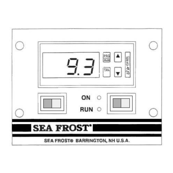
ELECTRONIC THERMOSTAT AND THERMOMETER
• The Sea Frost ETT's (Electronic Thermostat/Thermometer) accurate
operating settings and the programmable differential increases
efficiency. In comparison, mechanical controls tend to over run the
desired temperature range and must be set colder, running the
compressor longer, to maintain the proper average temperature.
• The ETT is powered by low voltage and will operate any Sea Frost
electric system, AC or DC.
• The ETT always shows cabinet temperature, displayed in Centigrade
or Fahrenheit.
• Accurate numerical setting of operating temperatures and differential
makes set up and temperature adjustment easy.
TEL (603) 868-5720
FAX (603) 868-1040
1-800-435-6708
www.seafrost.com
Advertisement
Table of Contents

Subscribe to Our Youtube Channel
Related Manuals for Sea Frost ETT’s


Summary of Contents for Sea Frost ETT’s
- Page 1 • The ETT is powered by low voltage and will operate any Sea Frost electric system, AC or DC. • The ETT always shows cabinet temperature, displayed in Centigrade or Fahrenheit.
- Page 2 • Thermometer mode when operating dual systems. • Wire leads allow mounting any distance from cabinet. • Black faceplate with red L.E.D. operation indicators. • Non-volatile memory, control will not loose settings. The ETT is pre-wired with plug in connectors for the two 10’ probes and 20’ harness included.
-
Page 3: Operation
INSTALLATION AND OPERATION MANUAL OPERATION The Sea Frost Electronic Thermostat and Thermometer (ETT) is an electronic device using two probes installed in the refrigerated space. One probe is sensing the cabinet temperature, which is displayed. The other probe controls the compressor operation by measuring the temperature of a cold plate. -
Page 4: Recommended Settings
To check the cut out setting (cold stopping point) push and hold the SEL button until ST-1 appears. Release the button and a number will flash. This is the cut out temperature. Push SEL again and the readout will return to box temperature. -
Page 5: Wire Routing
READOUT CHANGES ~ Fahrenheit to Centigrade To change the readout to centigrade hold down PRG and SEL for 5 seconds until 0 is displayed. Using the up and down arrows select #77, which is the password. Press SEL. Using the up and down arrows scroll to C-18. - Page 6 PROBE ATTACHMENT The probe with red bands must be in excellent thermal contact with the cold plate. Use the stainless steel clip provided, and attach it to the edge of the plate as shown in the drawing to the right. The probe without a red band should be installed at the mid point of the cabinet to get an accurate reading of the average temperature.
- Page 7 COMPRESSOR CONTROL WIRING HOOKUP AC Units – BG 1000 and Shore Assist Systems Connect the white and green wires from the ETT gray cable to the two red wires coming from the (CC) condensing unit. 12/24-Volt BD and Tradewinds Connect the white and green wires from the ETT gray cable to the end of the yellow harness.
- Page 8 AC Units – BG 1000 and Shore Assist Systems Wire the ETT to 12-volt DC power using a 2-amp fuse in order to maintain the temperature readouts. An optional 110-volt unit is available if needed. 12/24-Volt BD and Tradewinds See electrical connections in the unit manual. Crimp the red and black wires from the power source to the 12-10 gauge yellow piggyback terminals.
-
Page 9: Installation Kit
SEA FROST ELECTRONIC THERMOSTAT AND THERMOMETER DRILL (4) HOLES 3/32" FOR #6 SCREWS. Control Panel Head Sensor Probes (1-with red band, 1-without red band) 4-wire gray harness INSTALLATION KIT #6 x 1/2" flat head screws for mounting panel #6 x 1/2" pan head screws 3/16"...
Need help?
Do you have a question about the ETT’s and is the answer not in the manual?
Questions and answers