Table of Contents
Advertisement
Quick Links
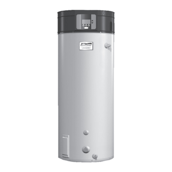
HIGH EFFICIENCY AHCG3/HCG360T120 thru AHCG3/HCG3100T250
COMMERCIAL GAS WATER HEATER
• INSTALLATION • OPERATION • SERVICE • MAINTENANCE • LIMITED WARRANTY
WARNING: If the information in these
instructions is not followed exactly, a fire
or explosion may result causing property
damage, personal injury or death.
– Do not store or use gasoline or other
flammable vapors and liquids in the
vicinity of this or any other appliance.
– WHAT TO DO IF YOU SMELL GAS:
• Do not try to light any appliance.
• Do not touch any electrical switch;
do not use any phone in your
building.
• Immediately call your gas supplier
from a neighbor's phone. Follow the
gas supplier's instructions.
• If you cannot reach your gas supplier,
call the fire department.
– Installation and service must be
performed by a qualified installer,
service agency or the gas supplier.
Thank you for buying this energy efficient water heater from
American Water Heaters. We appreciate your confidence
in our products.
TEXT PRINTED OR UNDERLINED IN RED CONTAINS
INFORMATION RELATIVE TO YOUR SAFETY. PLEASE
READ THOROUGHLY BEFORE INSTALLING AND USING
THIS APPLIANCE.
PLACE THESE INSTRUCTIONS ADJACENT TO HEATER AND
NOTIFY OWNER TO KEEP FOR FUTURE REFERENCE.
PRINTED 0608
GAS-FIRED POWER BURNER
FOR DOMESTIC HOT WATER
CAUTION
PO Box 1597, 500 Princeton Road
Johnson City, TN 37605
www.americanwaterheater.com
1
198154-000
Advertisement
Table of Contents

Subscribe to Our Youtube Channel
Related Manuals for American Water Heater AHCG3/HCG360T120


Summary of Contents for American Water Heater AHCG3/HCG360T120
- Page 1 HIGH EFFICIENCY AHCG3/HCG360T120 thru AHCG3/HCG3100T250 COMMERCIAL GAS WATER HEATER GAS-FIRED POWER BURNER FOR DOMESTIC HOT WATER • INSTALLATION • OPERATION • SERVICE • MAINTENANCE • LIMITED WARRANTY WARNING: If the information in these instructions is not followed exactly, a fire or explosion may result causing property damage, personal injury or death.
-
Page 2: Rough-In Dimensions
HIGH EFFICIENCY AHCG3/HCG360T120 thru AHCG3/HCG3100T250 ROUGH-IN-DIMENSIONS GAS VALVE PIPING AHCG3/HCG360T120 1/2" NPT AHCG3/HCG3100T150 thru 100T250 3/4" NPT Table 1. RECOVERY CAPACITIES - NATURAL GAS / L.P. Approx. TEMPERATURE RISE - DEGREES °F - GALLONS PER HOUR AHCG3/ Input Gallon HCG3 BTU/Hr. -
Page 3: Table Of Contents
TABLE OF CONTENTS PAGE PAGE ROUGH-IN DIMENSIONS ..............Gas Valves ..................FOREWORD ..................SYSTEM CONNECTIONS ..............FEATURES ..................Thermometers ................Relief Valve ................... Water Temperature Control ............Water Line Connections ............... High Limit Switch (E.C.O.) ............Heater Wiring ................Dishwashing Machine Requirement ..........USING THE ELECTRONIC CONTROLLER ........ -
Page 4: High Limit Switch (E.c.o.)
temperature be set for the lowest temperature which satisfies your hot water DISHWASHING MACHINE REQUIREMENT needs. This will also provide the most energy efficient operation of the water All dishwashing machines meeting the National Sanitation Foundation heater and minimize scale formation. requirements are designed to operate with water flow pressures between SETTING THE WATER HEATER TEMPERATURE AT 120°F/49°C WILL 15 and 25 pounds per square inch (103 Kpa and 173 Kpa). -
Page 5: Locating The Heater
LOCATING THE HEATER WARNING WARNING THIS WATER HEATER IS A CONDENSING UNIT AND REQUIRES A DRAIN TO BE LOCATED IN CLOSE PROXIMITY TO ALLOW THE CONDENSATE THERE IS A RISK IN USING FUEL BURNING APPLIANCES SUCH AS TO DRAIN SAFELY. THE CONDENSATE DRAINS FROM THE UNIT AT GAS WATER HEATERS IN ROOMS, GARAGES OR OTHER AREAS WHERE GASOLINE, OTHER FLAMMABLE LIQUIDS OR ENGINE THE EXHAUST ELBOW LOCATED AT THE BOTTOM OF THE UNIT. -
Page 6: Hard Water
HARD WATER If the confined space is within a building of tight construction, air for combustion and ventilation must be obtained from outdoors. When directly communicating with the outdoors through vertical ducts, two permanent openings, located Where hard water conditions exist, water softening or the threshold type of in the above manner, shall be provided. -
Page 7: Installation Requirements For The Commonwealth Of Massachusetts
INSTALLATION REQUIREMENTS FOR THE COMMONWEALTH OF MASSACHUSETTS For all side wall terminated, horizontally vented power vent, direct vent, and power direct vent gas fueled water heaters installed in every dwelling, building or structure used in whole or in part for residential purposes, including those owned or operated by the Commonwealth and where the side wall exhaust vent termination is less than seven (7) feet above finished grade in the area of the venting, including but not limited to decks and porches, the following requirements shall be satisfied: INSTALLATION OF CARBON MONOXIDE DETECTORS At the time of installation of the side wall horizontal vented gas... - Page 8 U.S. POWER VENT FIGURE 5a. CAUTION TO PREVENT EXHAUSTING PRODUCTS FROM CIRCULATING TO THE AIR INTAKE IN WINDY/COLD AREAS, THE MAXIMUM PRACTICAL DISTANCE BETWEEN THESE TWO TERMINALS IS RECOMMENDED. CANADIAN POWER VENT FIGURE 5b.
- Page 9 U.S. DIRECT VENT FIGURE 6a. CAUTION TO PREVENT EXHAUSTING PRODUCTS FROM CIRCULATING TO THE AIR INTAKE IN WINDY/COLD AREAS, THE MAXIMUM PRACTICAL DISTANCE BETWEEN THESE TWO TERMINALS IS RECOMMENDED. CANADIAN DIRECT VENT FIGURE 6b.
-
Page 10: Direct Venting
IMPORTANT FOR ALL MODELS The vent system must terminate so that proper clearances are maintained as cited in local codes or the current editions of the National Fuel Gas Code, ANSI Z223.1/NFPA 54 or the Natural Gas and Propane Installation Code, CAN/CSA-B149.1. -
Page 11: Vertical Vent Terminal Installation
VERTICAL VENT TERMINAL INSTALLATION 5. Glue the intake vent terminal to the section of the pipe. 6. Slide the wall plate over the pipe to stop against intake vent terminal. IMPORTANT 7. Place a bead of caulking (not supplied) around the gap between the pipe WHEN TERMINATING THROUGH A ROOF, THE FOLLOWING and the wall. -
Page 12: Installation Of Vent System
INSTALLATION OF VENT SYSTEM Propane Installation Code which requires the vent system components be certified to ULC S636. WARNING This water heater has been design certified to be vented with PVC pipe THE OPTIONAL INTAKE VENTING ARRANGEMENT AND THE EXHAUST certified and marked as complying with ULC S636. -
Page 13: Control And Switches
LOW GAS PRESSURE SWITCH CEMENT The cement should be a bodied cement of approximately 500 to 1600 (SEE FIGURE 12) centipoise viscosity containing 10-20% (by weight) virgin PVC material The Low Gas Switch (LGS) is a single-pole, normally open pressure switch solvated with tetrahydrofuran (THF). -
Page 14: Connection Of Gas Pipe
SYSTEM TO AVOID THE POSSIBILITY OF FIRE OR EXPLOSION WITH PROPERTY DAMAGE, PERSONAL INJURY OR LOSS OF LIFE. FIGURE 14c. AHCG3/HCG360T120 Models Only The Gas Leak Test is performed as follows: Paint pipe connections upstream of gas control with a rich soap and water solution to test for leaks before operating main burner. -
Page 15: Purging
RELIEF VALVE DISCONNECT THE APPLIANCE AND ITS MANUAL GAS SHUTOFF VALVE FROM THE GAS SUPPLY PIPING SYSTEM DURING ANY SUPPLY PRESSURE TESTING EXCEEDING 1/2 PSIG (3.45Kpa). GAS This heater is equipped with an approved temperature and pressure relief SUPPLY LINE MUST BE CAPPED WHEN DISCONNECTED FROM THE valve. -
Page 16: Heater Wiring
3. This unit may never be connected to any existing heating system or CONDITIONER MUST BE INSTALLED IF THE ABOVE CONDITIONS EXIST. component(s) previously used with non-potable water heating MALFUNCTIONS CAUSED BY A POOR ELECTRICAL SUPPLY ARE NOT COVERED UNDER YOUR WARRANTY. appliance. -
Page 17: Using The Electronic Controller
USING THE ELECTRONIC CONTROLLER 1. Overview Interaction with the water heater controller is done through an up, a down, and three operation buttons. These buttons are illustrated to the right. Operation of the three lower buttons is defined immediately above them on the screen. The [UP] and [DN] buttons are used to navigate through the menus and make adjustments to the water heater. -
Page 18: Operating States
2. Operating States In the main desktop screen, there are some specific Operating States that are indicated on the status line. These are summarized below: 3. Adjusting the Operating Set Point ACTION: Press Change then use the UP and DOWN buttons to change the Set The Operating Set Point of this water heater determines the regulated Point. -
Page 19: Changing The Display Units
4. Changing the Display Units There are two types of conditions that can occur during operation. These are Warnings and Faults: The display interface to the heater has the option of selecting between de- grees Fahrenheit and degrees Celsius for temperature displays. This can be •... -
Page 20: Viewing The Fault History
7. Viewing the Fault History ACTION: To get to the current fault information screen, press Menu. The controller for this water heater will store a history of ten of the last Fault and Warning conditions that occurred. This is stored in the Fault History. DISPLAY: Along with all the information about the fault, including a estimate time of when the fault occurred, information regarding the advanced diagnostics for... -
Page 21: Operating Instructions
ADJUSTMENT PROCEDURE input rating with sufficient gas pressure at the valve, check to ensure INITIAL START-UP - AHCG3/HCG360T120 thru AHCG3/HCG3100T150 the unit is equipped with the correct orifice. Main line gas pressure to the water heater for natural gas should be between ADJUSTMENT PROCEDURE a maximum of 10.5"... -
Page 22: Cathodic Protection
10,100 ft. (3078 m). The CATHODIC PROTECTION AHCG3/HCG360T120 and AHCG3/HCG3100T150 heaters are certified for use without modifications for altitudes up to 7,700 ft. (2347 m). Installations above these altitudes may require replacement of the burner orifice. Call the CAUTION 800 number listed on the unit for requirements. -
Page 23: For Your Safety Read Before Operating
FOR YOUR SAFETY READ BEFORE OPERATING WARNING: If you do not follow these instructions exactly, a fire or explosion may result causing property damage, personal injury or loss of life. AHCG3/HCG360T120 MODELS ONLY. - Page 24 FOR YOUR SAFETY READ BEFORE OPERATING WARNING: If you do not follow these instructions exactly, a fire or explosion may result causing property damage, personal injury or loss of life. OPERATING INSTRUCTIONS TURN OFF GAS TO APPLIANCE AHCG3/HCG3100T150 MODELS ONLY.
- Page 25 FOR YOUR SAFETY READ BEFORE OPERATING WARNING: If you do not follow these instructions exactly, a fire or explosion may result causing property damage, personal injury or loss of life. OPERATING INSTRUCTIONS OPERATING INSTRUCTIONS TURN OFF GAS TO APPLIANCE TURN OFF GAS TO APPLIANCE AHCG3/HCG3100T199 &...
-
Page 26: Flushing
POWERED ANODE SYSTEM heater should be delimed every 3 months. The AHCG3/HCG360T120 thru AHCG3/HCG3100T250 heaters are factory Sediment and lime scale removal may be accomplished through the cleanout equipped with a powered anode system. The anodes are of a permanent opening furnished on the heater, see Figure 25. -
Page 27: Drain Valve And Access Panels
DRAIN VALVE AND ACCESS PANELS to build until the relief valve actuation pressure is equaled. Then, the relief valve will open, allowing some water to escape, slightly lowering The heaters are equipped with a 3/4" drain valve. the pressure. An access panel covers the cleanout opening in the tank which is sealed by Contact your water supplier or local plumbing inspector on how to control a gasket and cover, figure 25. -
Page 28: Installation Diagrams
INSTALLATION DIAGRAMS ONE TEMPERATURE - ONE HEATER VERTICAL STORAGE TANK FORCED CIRCULATION WITH OR WITHOUT BUILDING RECIRCULATION CAUTION: IF BUILDING COLD WATER SUPPLY HAS A BACK- FLOW PREVENTER, CHECK VALVE OR WATER METER WITH CHECK VALVE PROVISIONS FOR THERMAL EXPANSION OF WATER IN THE HOT WATER SYSTEM MUST BE PROVIDED NOTE: CONNECT RETURN... - Page 29 TWO TEMPERATURE - ONE HEATER HIGH TEMPERATURE WITH OR WITHOUT BUILDING RECIRCULATION PIPE RELIEF VALVE TO OPEN DRAIN. DANGER N O T E : TEMPERATURE SETTING SHOULD NOT EXCEED I F T E M P E R E D W AT E R I S RECIRCULATED, RETURN LINE SHOULD SAFE TEMPERATURE AT FIXTURES.
- Page 30 TWO TEMPERATURE - TWO HEATERS HIGH TEMPERATURE WITH OR WITHOUT BUILDING RECIRCULATION CAUTION: IF THE PLUMBING REQUIRES THE USE OF PIPES WITH DISSIMILAR MATERIAL (FOR EXAMPLE, STEEL AND COPPER), USE DIELECTRIC UNIONS TO PREVENT AN ELECTRO-GALVANIC ACTION BETWEEN THE PIPING COMPONENTS WITH DISSIMILAR MATERIALS.
- Page 31 TWO TEMPERATURE - TWO HEATERS (ONE PRE-HEATER/ONE BOOSTER HEATER) WITH OR WITHOUT BUILDING RECIRCULATION * PIPE RELIEF VALVE TO OPEN DRAIN DANGER TEMPERATURE SETTING SHOULD NOT EXCEED SAFE TEMPERATURE ** 140°F (60°C) TO 150°F (66°C) SHOULD BE MAXIMUM WATER AT FIXTURES. SEE WATER TEMPERATURE CONTROL WARNING ON TEMPERATURE MAINTAINED IN THE PRE-HEATERS.
- Page 32 TWO TEMPERATURE - ONE HEATER HIGH TEMPERATURE WITH RECIRCULATION OF SANITIZING LOOP CAUTION: IF THE PLUMBING REQUIRES THE USE OF PIPES WITH DISSIMILAR MATERIAL (FOR EXAMPLE, STEEL AND COPPER), USE DIELECTRIC UNIONS TO PREVENT AN ELECTRO-GALVANIC ACTION BETWEEN THE PIPING COMPONENTS WITH DISSIMILAR MATERIALS.
-
Page 33: Manifold Kits
MANIFOLD KITS Precision cut type “L” all copper manifold kits assure water flow balance of all units. Without this balance, the full water heating and storage potential of the system cannot be achieved. Plus, the units with the higher water flow may have a shortened life. Dimensions shown are for minimum space occupied by the water heaters assemblies. -
Page 34: Checklist And Service Information
CHECKLIST AND SERVICE INFORMATION 2. Some of the electrical components of the water heater make sounds which are normal. IMPORTANT • Contacts click or snap as the heater starts and stops. The installer may be able to observe and correct certain problems which •... -
Page 35: Replacement Parts
4.0"WC (.98kPa) for natural gas and 10.0"WC (2.46kPa) MOTOR RUNS, PREPURGE TIME ELAPSES BUT MAIN for propane gas for the AHCG3/HCG360T120 & AHCG3/HCG3100T150 FLAME NOT ESTABLISHED. models and 0"WC (0kPa) for both natural and propane gas AHCG3/ HCG3100T199 &... -
Page 36: Limited Warranty
If the glass-lined tank in this water heater shall prove upon examination by the warrantor to have leaked due to natural corrosion from potable water therein, during the first THREE years after initial installation, the warrantor will supply a complete new American water heater of equivalent size and current model. - Page 37 NOTES:...
- Page 38 NOTES:...
- Page 39 NOTES:...
- Page 40 PO Box 1597, 500 Princeton Road Johnson City, TN 37605 Phone: 1-800-456-9805 www.americanwaterheater.com...
Need help?
Do you have a question about the AHCG3/HCG360T120 and is the answer not in the manual?
Questions and answers