Table of Contents
Advertisement
Advertisement
Table of Contents

Related Manuals for Rich electric INVERTEK L series


Summary of Contents for Rich electric INVERTEK L series
-
Page 2: Table Of Contents
Content General Introduction Application Features Included Safety Instructions Introduction Front View & Main Functions Rear View & Main Functions Left View & Main Functions Pre-installation Information Electrical Requirements Installation Requirements Connection and Testing Operation Power Saving Adjustment Trouble Shooting Maintenance Circuit Configuration of the Inverter Specifications... -
Page 3: General Introduction
A. General Introduction: Rich Electric designers are experts in Compact High and Low Frequency Power Inverters. Our engineers are making use of advanced high frequency design that results in an inverter is smaller, lighter and easier to use than any other inverter with similar power ratings. -
Page 4: Safety Instructions
D. Safety Instructions: 1. General Safety Precautions: Do not expose the Inverter to rain, snow, spray, bilge or dust. To reduce risk of hazard, do not cover or obstruct the ventilation openings. Do not install the inverter in zero-clearance compartment. Over hearting may result. -
Page 5: Introduction
4. Installation and Operation: To get the most out of the power inverter, it must be installed and used properly. E. Introduction: The power inverter series are the member of the most advanced line of mobile AC power systems available. To get the most out of the power inverter, it must be installed and used properly. -
Page 6: Front View & Main Functions
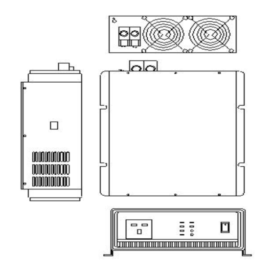
F. Front View & Main Functions: 1. ON/OFF SWITCH: Power ON/OFF switch, leave in the OFF position during installation. 2. LED INDICATION: OVP: Over voltage protection. OTP: Over Temperature Protection. UVP: Under voltage protection OLP: Over Load Protection POWER: Power ON. RUN/STANDBY: Indicates current operating condition of the inverter. -
Page 7: Rear View & Main Functions
G. Rear View & Main Functions: 1. Ventilation window: Do not obstruct; allow at least 1 inch for airflow. 2. Battery terminals: Connect to 12V / 24V /48V battery or other 12V / 24V / 48V power source. (+) is positive, (-) is negative. WARNING! Reverse polarity connection will blow internal fuse and may damage inverter permanently. -
Page 8: Pre-Installation Information
I. Pre-installation Information: Before installing your inverter, please make sure that you have appropriately-sized batteries. A battery that is too small will not allow the inverter to perform to its full specification. J. Electrical Requirements: DC input voltage of the inverter must be the same as the battery bank voltage. - Page 9 and sizes. Do not mount the inverter where it will be exposed to the gases produced by the battery. These gases are very corrosive and prolonged exposure will damage the inverter. Wall-mount – Inspection and operation are more convenient if the unit is mounted at head height and the DC cables hang naturally out of the way.
-
Page 10: Connection And Testing
4. Ground Fault Circuit Interrupters (GFCI’s): Installations in Recreational Vehicles (for North American approval) will require GFCI protection of all branch circuits connected to the AC output of the inverter. In addition, electrical codes require GFCI protection of certain receptacles in residential installations. - Page 11 3. Before proceeding further, carefully check that cable you have just connected from the negative terminal of inverter to the Negative terminal of battery. 4. Connect the RED cable from the positive terminal of inverter to the positive terminal of the battery. Make secure connection. 5.
-
Page 12: Operation
M. Operation: To operate the power inverter, turn it on using the ON/OFF switch on the front panel. The power inverter is now ready to deliver AC power your loads. If you are operating several loads from the power inverter, turn them on separately after the inverter has been turned on. -
Page 13: Power Saving Adjustment
N. Power Saving Adjustment: Your inverterk inverter features automatic load-sensing, which allows the inverter to wait in Standby mode until an AC load is switched ON. When an AC load appears, the inverter will immediately start. This feature conserves valuable battery energy as the inverter uses only about 10% of normal power when in standby mode (standby is indicated by flashing green lamp). -
Page 14: Trouble Shooting
O. Trouble Shooting: AC output does not stay ON. Some AC loads may not be large enough to hold the inverter ON. This condition is indicated by the inverter turning off after every eight to ten seconds, then back on again. - Page 15 Move the television as far away from the power inverter as possible. Keep the cables between the battery and the power inverter as short as possible and twist tem together with about 2 to 3 twists per foot. This minimizes radiated interference from the cables.
-
Page 16: Maintenance
P. Maintenance: Very little maintenance is required to keep your inverter operating properly. You should clean the exterior of the unit periodically with a damp cloth to prevent accumulation of dust and dirt. At the same time, tighten the screws on the DC input terminals. Q. -
Page 17: Specifications
R. Specifications DAI – 0150L - 1 2 1 A TYPE A-N. American 0150 WATT INPUT 0300 WATT 12 VDC OUTPUT B-U.K. DC TO AC INVERTER 0600 WATT 24 VDC 1-110 V 1000 WATT 48 VDC 2-220 V C-Australia 1500 WATT 3000 WATT D-Europe E-Universal...
Need help?
Do you have a question about the INVERTEK L series and is the answer not in the manual?
Questions and answers