Table of Contents
Advertisement
Advertisement
Table of Contents

Subscribe to Our Youtube Channel
Related Manuals for Growatt Shine WebBox

Summary of Contents for Growatt Shine WebBox
-
Page 2: Table Of Contents
Server Function 4.1 Network Access via Integrated Server 4.2 Setting Shine WebBox via Integrated Server Uploading Data to Shine Server 5.1 Registering and Logging in 5.2 Creating New Plant 5.3 Adding Shine WebBox 5.4 Visiting the Data from Shine WebBox... - Page 3 7.3 Manage Active and Reactive Power Simultaneously 7.4 PV Power Station Solution Device Maintenance 8.1 Firmware Update 8.2 Stopping the Shine WebBox 8.3 Resetting the Shine WebBox 8.4 Clearing up the Record 8.5 Troubleshooting 8.6 Maintenance and Care Technical Data 9.1 Shine WebBox...
-
Page 4: Copyright Statement
1.1 Copyright Statement Copyright © 2012 Shenzhen Growatt New Energy Co,.Ltd, hereinafter referred to as ‘Growatt’. All right reserved. No part of this document may be reproduced, stored in a retrieval system, or transmitted, in any form or by any means, electronic, mechanical, photographic, magnetic or otherwise, without the prior written permission of Growatt New Energy. -
Page 5: Guideline
1.4 Guideline Before using the Shine WebBox, please read the manual carefully. In the meantime, please keep it well, lest maintenance staff may not find it later. All the content, pictures, logos, symbols are reserved. No part of this document may be transmitted in any form without the prior written permission of our internal staff. -
Page 6: Device Overview
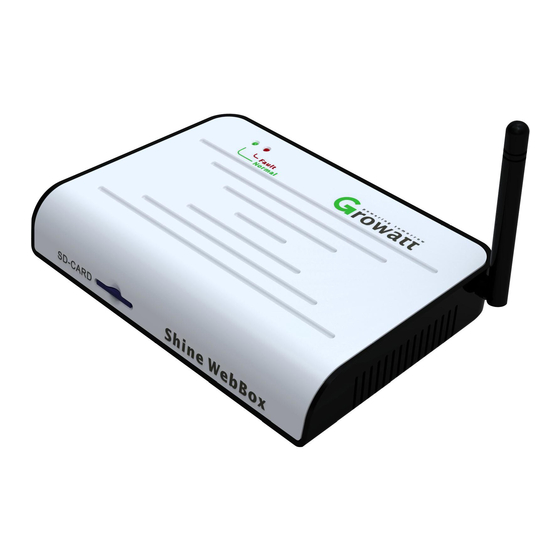
Production Description 2.1 Device Overview 1.SWITCH 2.POWER 3.RS-232 4.LAN 6.USB 5.COM 10.Fault-LED 8.ANTENNA 9.Normal-LED 7.SD-CARD... - Page 7 2.1.1 Interface The description of Shine WebBox Interface is listed below. Name Label Function SWITCH Power Switch:Turn On/Off Shine WebBox Power Port Power Line:Connect the power line to charge LAN Port RJ45 port:Connect Shine WebBox to the local network area of Shine Server through web line...
-
Page 8: Unpacking
2.2 Unpacking 2.2.1 Packing List The Shine WebBox and accessories can be found as below. Label Amount Name Shine WebBox 5V Power Adapter 2G SD Card Terminal ( used for RS485 and ripple control receiver) 2pcs Plastic Column 2pcs M3.5*20 Screw Spike... -
Page 9: Shine Webbox Network Introduction
Shine WebBox can monitor the PV devices by RS485 or ZigBee. Shine WebBox can make up a local area network by router or switching machine. You have local access by means of internal IP address. Otherwise, our WebBox can upload the data to our server and then you get remote access of the data throughout the realm name. -
Page 10: Requirements For Installation Location
The maximum length of network cable used to connect switch or router is not more · than 100m. 3.2 Shine WebBox Installation 3.2.1 Vertically Installation Installation Procedure: 1. Install the bracket on the vertical plane of the wall. Dig two holes according to the dimension of the bracket, there are two screw holes. - Page 11 2. Hang Shine WebBox onto the bracket through the calabash ports in the back of Shine WebBox. 3. Finish the mounting of Shine WebBox, notice the clearance of mounting. 4. Connect the Shine WebBox and inverter using RS485 cables via the RS485 ports on them.
-
Page 12: Network Connection
6. Insert the SD card: Insert the SD card into the SD card port on Shine WebBox, notice that SD card must be inserted before powering on Shine WebBox or the SD card would not be recognized. 7. Connect the power line: connect the power line to the power port on Shine WebBox. - Page 13 “Internet Protocol → TCP/IP Properties” “Use the following IP address”, set the IP address of the PC and → Shine WebBox to be the same network segment. Set the IP address of PC referring to following pictures:...
- Page 14 2. Windows 7 OS Click to open “Network” “Connection to a network” “Local Connection” → → → “Internet Protocol version 4 (TCP/IPv4)”, change the IP address of the PC and Shine WebBox to be the same network segment.
- Page 15 3.3.2 Directly Connect to the PC 1. Power on the Shine WebBox and connect to the PC via network cables, the RJ45 ports on Shine WebBox. 2. Set the IP address, default gateway. Please confirm the IP address of the PC and...
- Page 16 1. Connect the PC and Shine WebBox to the network ports of network switch. 2. Set the IP address of the PC and Shine WebBox to be in the same segment. 3. Power on the PC, Shine WebBox and network switch then it’s available to get...
-
Page 17: Connection To Pv System
1. PV devices are connected to Shine WebBox via RS485 cable connection. Note that Pin 1 of RS485 is corresponded to Pin 4 of Shine WebBox Com port; while Pin 2 of RS484 is corresponded to Pin 2 of Shine WebBox COM port. -
Page 18: Network Access Via Integrated Server
Shine WebBox Integrated Server Function 4.1 Network Access via Integrated Server In order to get access to integrated server of the Shine WebBox, please confirm the wiring of devices is OK and the setting of IP address is correct. After that, start the web browser and enter 192.168.1.230 in the address bar. - Page 19 Chapter 2.1.2). Once any new inverter is detected, it will be displayed in the record interface. The Shine WebBox will display the updated data automatically. 5. Always log out from the Shine WebBox when you finish your work on the Shine WebBox. To do so, just close the Web browser.
-
Page 20: Setting Shine Webbox Via Integrated Server
DNS: 192.168.1.1 1. You are able to operate the Shine WebBox by using integrated web browser in the local network. Click on “parameter” to go to the setting page. 2. Select “local_ip”, enter the fixed IP number if you want to change the IP address, for example the default address is 192.168.1.230, and you can change it to... - Page 21 5. Normally DNS is equal to the default gateway. Also you can set the DNS same as the network. 6. After configuration, click on “save” at the bottom. After setting the IP address successfully, restart the Shine WebBox, then you can get access to the WebBox using web browser by entering the new IP address. Save 4.2.1.2 Setting IP Address of the Server...
- Page 22 3. If the parameters about ZigBee have been modified in the web browser accessing to the Shine WebBox, the configuration of ZigBee module connecting to the inverter also needs to be modified. As to detailed information, please refer to ZigBee module user manual.
- Page 23 1. In “parameter” field, select “environment:addren”, choose “ON”, then click on “save”. After that, Shine WebBox could operate environmental monitor. The address of the environmental monitor is 36, which should not be modified. Please set the address of environmental monitor to 36 in its own LCD interface, and select “Modbus”...
- Page 24 4.2.4 Setting Power Management In “parameter” field, select “power Adjust”, choose “ON”. In a local network, only one Shine WebBox can be chosen as host, the others should be set as slave. Host Power Adjust: 4.2.5 Fault Indication There are two ways to indicate the inverter fault: 1.
-
Page 25: Registering And Logging In
Shine WebBox does not only provide monitoring locally, remote monitoring method is also available via Shine Server. The Shine WebBox will upload the status and data of the inverters to the Shine Server. You can visit the historical data, real-time data, historical chart and real-time chart from the interface of the Shine Server. -
Page 26: Creating New Plant
5.2 Creating New Plant 1. After registering successfully, it will redirect to the Shine Server Home page automatically. 2. Click on “New Plant”, and you will turn to the “new plant” page below. -
Page 27: Adding Shine Webbox
3. Fill in the plant information and click “summit”. It will redirect to the “Plant list” on the home page, which means we have finished the “new plant” work. 5.3 Adding Shine WebBox Adding the Shine WebBox to make it connected to Shine Server. 1. Click “Setting” → Select “Devices Management”. - Page 28 2. Click “Data Logger” and add the Shine WebBox. 3. Fill in the information of Data Logger “Serial Number” and “validate code”. After choosing the plant type, click “summit” to finish all the work.
-
Page 29: Visiting The Data From Shine Webbox
5.4 Visiting the Data from Shine WebBox 1. Click “inverter” under the list of plant list, the overview of inverters is below. 2. Click the real-time chart, real-time data, historical chart and historical data on the left to view the whole data. -
Page 30: Installing The Shine Station
Uploading Data to the Shine Station The monitoring data in the Shine WebBox could be viewed via the Shine Station. 6.1 Installing the Shine Station The installation procedure is brief. Just double click the installer, and carry out the operation according to the prompt. - Page 31 Start web browser (Google Chrome is recommended), enter the native IP address and port number 5678, e.g. the native IP address of the server or computer installed with Shine Station is 192.168.1.74, then enter 192.168.1.74:5678 or 127.0.0.1:5678 in the web browser. The operation of the Shine Station could be carried out after logging in.
-
Page 32: Checking Up The Data
Click on “Start Server”, enable the monitoring service. When the Shine WebBox is connected to the Shine station well, the setting status will display as below. 6.4 Checking Up the Data When Shine WebBox connects to the Shine Station well, the plant status could be viewed via the Shine Station. -
Page 33: Power Management
To enable power management, a ripple control receive is required. This function is available when user activates it. The COM ports of the Shine WebBox are shown as below. Pin 1,3,5,7,9,11 are used to connect the ripple control receiver. -
Page 34: Reactive Power Control
0% of nominal power. 7.2 Reactive Power Control There are 4 power factor levels, 0.99, 0.98, 0.97, and 0.95. The connection between ripple control receiver and Shine WebBox is shown as below. 0.95 0. 97 0.98 0.99... - Page 35 0.95 7.3 Manage Active and Reactive Power Simultaneously If active power and reactive power need to be managed at the same time, connect the Shine WebBox with two ripple control receivers as below.
-
Page 36: Pv Power Station Solution
7.4 PV Power Station Solution In PV power station, there are more than one WebBox. You can choose one WebBox as the host and connect it to the ripple control receiver. The host WebBox could send commands to other WebBoxs (slave WebBox) by the local network. Normally, the ripple control receiver would send commands to the host WebBox if power management is required. -
Page 37: Device Maintenance
The integrated user interface is required in the local network when resetting the shine WebBox. 1. In “parameter” field, select “Enable_Reset”. Enable Enable Enable _Reboot _Reset _Clear_record Save Back Home 2. Click on “save”. The Shine WebBox would restore factory settings after restarts. -
Page 38: Clearing Up The Record
Enable Enable _Reboot _Reset _Clear_record Save Back Home 2. Click on “save”, all the records would be wiped out after the Shine WebBox restarts. 8.5 Troubleshooting Cause Rectification Problem The Shine WebBox The address of inverter Reset inverter address to fixed one is not available. -
Page 39: Shine Webbox
Technical Data 9.1 Shine WebBox Mechanical data 185mm* 125mm * 30mm Width*height*depth 420g Net weight Environmental conditions Ambient temperature 0 ℃… 45℃ IP 20 Degree of protection Mounting location Indoor Communication Rs485 communication Maximum 30 inverters ZigBee maximum 15 inverters... -
Page 40: Accessories
9.3 Accessories 9.3.1 SD Card The SD card with 2GB of memory used in the Shine WebBox could be valid for 5 years. 9.3.2 RS485 Cable To ensure the stable communication between the Shine WebBox and inverters, the RS485 cable that consists of STP (shielded twisted pair) is preferred. The maximum cable length of RS485 communication bus is 1200m. - Page 41 Contact If you have technical problems concerning our products, please contact the Growatt serviceline. GROWATT NEW ENERGY Building B, Jiayu Industrial Zone, #28 Guanghui Road, Longteng Community, Shiyan, Baoan District, Shenzhen, P.R.China. Growatt Serviceline Tel: +86 755 27471942 E-mail: service@ginverter.com...
Need help?
Do you have a question about the Shine WebBox and is the answer not in the manual?
Questions and answers