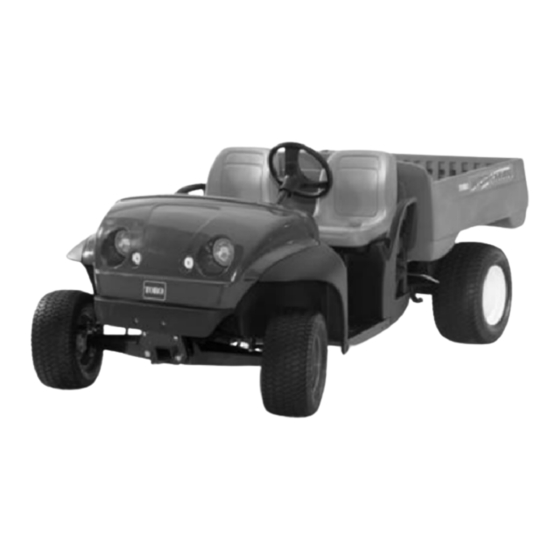
Table of Contents

Advertisement

Preface
The purpose of this publication is to provide the service
technician with information for troubleshooting, testing
and repair of major systems and components on the
Workman e2050 and e2065.
REFER TO THE OPERATOR'S MANUAL FOR OPER-
ATING, MAINTENANCE AND ADJUSTMENT IN-
STRUCTIONS. Space is provided in Chapter 2 of this
book to insert the Operator's Manuals and Parts Cata-
logs for your machine. Replacement Operator's Manu-
als are available on the Internet at www.toro.com.
The Toro Company reserves the right to change product
specifications or this publication without notice.
Workman
E The Toro Company - - 2004, 2006, 2007, 2011
Service Manual
e2050 & e2065
R
This safety symbol means DANGER, WARNING
or CAUTION, PERSONAL SAFETY INSTRUC-
TION. When you see this symbol, carefully read
the instructions that follow. Failure to obey the
instructions may result in personal injury.
NOTE: A NOTE will give general information about the
correct operation, maintenance, service, testing or re-
pair of the machine.
IMPORTANT: The IMPORTANT notice will give im-
portant instructions which must be followed to pre-
vent damage to systems or components on the
machine.
Part No. 04127SL (Rev. D)

Advertisement

Table of Contents
loading

Summary of Contents for Toro WorkmanR e2050

  • Page 1 IMPORTANT: The IMPORTANT notice will give im- portant instructions which must be followed to pre- vent damage to systems or components on the machine. E The Toro Company - - 2004, 2006, 2007, 2011...
  • Page 2 This page is intentionally blank. Workman e2050/e2065...
  • Page 3 Table Of Contents Chapter 1 – Safety Safety Instructions ......1 – 2 Jacking and Other Instructions .
  • Page 4 This page is intentionally blank. Workman e2050/e2065...
  • Page 5: Table Of Contents

    Chapter 1 Safety Table of Contents SAFETY INSTRUCTIONS ..... . JACKING AND OTHER INSTRUCTIONS ..Before Operating .
  • Page 6: Safety Instructions

    A replacement Operator’s Manual is chine. Also tighten any loose nuts, bolts or screws to en- available on the Internet at www.Toro.com. sure machine is in safe operating condition. While Operating 3.
  • Page 7: Maintenance And Service

    13.To assure optimum performance and continued Carefully remove one of the battery cables from the bat- safety of the machine, use genuine Toro replacement tery pack as the first step in any repair. Once a battery parts and accessories. Replacement parts and acces-...
  • Page 8: Jacking And Other Instructions

    Jacking and Other Instructions Jacking Vehicle DANGER POTENTIAL HAZARD • A vehicle that is not properly supported may become unstable. WHAT CAN HAPPEN • The vehicle may move or fall. Personal injury or damage to the machine may result. HOW TO AVOID THE HAZARD •...
  • Page 9: Safety And Instruction Decals

    Workman vehicle. If any decal becomes illegible or damaged, install a new decal. Part numbers are listed in the Parts Catalog. Order replacement decals from your Authorized Toro Distributor. Workman e2050/e2065 Page 1 – 5 Safety (Rev. B)
  • Page 10 This page is intentionally blank. Safety (Rev. B) Page 1 – 6 Workman e2050/e2065...
  • Page 11 Chapter 2 Product Records and Maintenance Table of Contents PRODUCT RECORDS ......Standard Torque for Dry, Zinc Plated and EQUIVALENTS AND CONVERSIONS .
  • Page 12: Equivalents And Conversions

    Equivalents and Conversions 0.09375 Product Records and Maintenance (Rev. B) Page 2 – 2 Workman e2050/e2065...
  • Page 13: Torque Specifications

    For critical applications, as determined reduced by 25% for lubricated fasteners to achieve by Toro, either the recommended torque or a torque that the similar stress as a dry fastener. Torque values may is unique to the application is clearly identified and spe- also have to be reduced when the fastener is threaded cified in this Service Manual.
  • Page 14 Standard Torque for Dry, Zinc Plated and Steel Fasteners (Inch Series) Grade 1, 5, & SAE Grade 1 Bolts, Screws, Studs & SAE Grade 5 Bolts, Screws, Studs & SAE Grade 8 Bolts, Screws, Studs & Thread Size 8 with Thin Sems with Regular Height Nuts Sems with Regular Height Nuts Sems with Regular Height Nuts...
  • Page 15 Standard Torque for Dry, Zinc Plated and Steel Fasteners (Metric Fasteners) Class 8.8 Bolts, Screws and Studs with Class 10.9 Bolts, Screws and Studs with Thread Size Thread Size Regular Height Nuts Regular Height Nuts Regular Height Nuts Regular Height Nuts (Class 8 or Stronger Nuts) (Class 10 or Stronger Nuts) M5 X 0.8...
  • Page 16 Other Torque Specifications SAE Grade 8 Steel Set Screws Wheel Bolts and Lug Nuts Recommended Torque Thread Size Recommended Torque** Thread Size Thread Size Square Head Hex Socket 7/16 – 20 UNF 65 + 10 ft–lb 88 + 14 N–m Grade 5 1/4 –...
  • Page 17 Maintenance Maintenance procedures and recommended service in- tervals for the Workman e2050 and e2065 are covered in the Operator’s Manual. Refer to that publication when performing regular vehicle maintenance. Workman e2050/e2065 Page 2 – 7 Product Records and Maintenance (Rev. B)
  • Page 18 This page is intentionally blank. Product Records and Maintenance (Rev. B) Page 2 – 8 Workman e2050/e2065...
  • Page 19 Chapter 3 Electrical System Table of Contents ELECTRICAL DIAGRAMS ..... SERVICE AND REPAIRS ..... GENERAL INFORMATION .
  • Page 20: Electrical Diagrams

    Electrical Diagrams The electrical schematic, circuit drawings and wire har- ness drawings for the Workman e2050 and e2065 are located in Chapter 6 – Electrical Diagrams. Electrical System (Rev. B) Workman e2050/e2065 Page 3 – 2...
  • Page 21: General Information

    General Information The Workman e2050 and e2065 use a 48 volt DC elec- After performing any repair on electrical components on trical system that is an isolated circuit. The vehicle frame the vehicle, make sure that wiring is routed and secured is not used for any ground connections.
  • Page 22: Vehicle Operation

    Vehicle Operation The Workman e2050 and e2065 electrical system use The vehicle controller is a sealed electronic logic device a 48 volt battery pack, an electric traction motor, a ve- that uses inputs from several vehicle components to hicle controller and numerous other electrical compo- control motor speed and direction.
  • Page 23: Special Tools

    Multimeter The multimeter can test electrical components and cir- cuits for current, resistance or voltage. NOTE: Toro recommends the use of a DIGITAL Volt– Ohm–Amp multimeter when testing electrical circuits. The high impedance (internal resistance) of a digital me- ter in the voltage mode will make sure that excess cur- rent is not allowed through the meter.
  • Page 24 Battery Watering Dispenser Use the battery watering dispenser when adding dis- tilled water to vehicle batteries. Obtain watering dis- penser locally. Figure 6 Battery Hydrometer Use the battery hydrometer when measuring specific gravity of battery electrolyte. Obtain hydrometer locally. Figure 7 Battery Lift Strap Use the battery lift strap to remove and install batteries from the vehicle.
  • Page 25 Workman bat- tery pack and also for finding faulty battery or batteries in the battery pack. Order the 36/48 Volt Battery Discharge Unit (TOR4106) from your Toro Distributor. Figure 9 Workman e2050/e2065 Electrical System (Rev. B) Rev.
  • Page 26: Troubleshooting

    Troubleshooting For effective troubleshooting and repairs, there must be CAUTION a good understanding of the electrical circuits and com- ponents used on this vehicle (see Electrical Schematic in Chapter 6). Remove all jewelry, especially rings and watches, before doing any electrical trouble- If the vehicle has any switches by–passed, they must be shooting or testing.
  • Page 27: Battery Charger Operation

    General Run Problems (Continued) Problem Possible Causes Traction motor stops during operation. Wiring to the traction motor components (e.g. main contactor, controller, traction motor) loose, corroded or damaged (see Electrical Schematic in Chapter 6 – Electrical Diagrams). Battery cables are loose, corroded or damaged. Controller is overheated.
  • Page 28: Battery Charger Problems

    Battery Charger Problems Problem Possible Causes Battery charger does not turn on. AC outlet fuse/circuit breaker blown. AC outlet is faulty. Vehicle wiring is loose or damaged (see electrical schematic in Chapter 6 – Electrical Diagrams). Fusible link FL1 is damaged. Vehicle charger interlock switch or circuit wiring faulty.
  • Page 29: Adjustments

    Adjustments Accelerator Switch Adjustment 1. Position vehicle on a level surface, turn On/Off switch OFF and remove key. Apply parking brake. 2. Make sure that at complete brake pedal travel, the park detent and pawl are fully engaged. If needed, ad- just the accelerator pedal stop cap screw to allow full en- gagement (Fig.
  • Page 30: Accelerator Potentiometer Adjustment

    Accelerator Potentiometer Adjustment The accelerator potentiometer is used as one of the in- puts for the vehicle controller and is attached to the ped- al frame under the dash (Fig. 13). A collar with roll pin on the accelerator pedal shaft positions the accelerator po- tentiometer lever.
  • Page 31: Accelerator System Calibration

    Accelerator System Calibration The accelerator system on the Workman e2050 and e2065 includes the accelerator pedal assembly, the ac- celerator potentiometer, the accelerator switch and the controller. If any of these components are adjusted, re- moved or replaced, the following calibration procedure should be performed.
  • Page 32: Component Testing

    Component Testing For accurate resistance and/or continuity checks, elec- trically disconnect the component being tested from the CAUTION circuit (e.g. disconnect the harness wire connectors from the vehicle on/off switch before doing a continuity check on the on/off switch). When testing electrical components for continu- ity with a multimeter (ohms setting), make sure that power to the circuit has been disconnected.
  • Page 33: Battery Discharge Indicator And Hour Meter Gauge

    Battery Discharge Indicator and Hour Meter Gauge The combination battery discharge indicator and hour meter gauge is located on the dash panel (Fig. 19). The battery indicator identifies state of charge of the bat- tery pack. The battery indicator reads full (10 bars) when the battery pack is fully charged (approximately 51 volts).
  • Page 34: Vehicle Direction (Forward/Reverse) And Headlight Switches

    Vehicle Direction (Forward/Reverse) and Headlight Switches The vehicle direction (forward/reverse) switch (Fig. 21) and headlight switch (Fig. 22) are located on the control panel. These two switches have identical logic. The vehicle direction switch is one of several inputs for the vehicle controller and allows the direction (forward/ reverse) of the vehicle to be changed by the operator.
  • Page 35: Vehicle Status Light

    Vehicle Status Light The vehicle status light is located on the control panel (Fig. 24). During normal operation, the status light should be continuously illuminated. A vehicle electrical problem will be identified by a flashing status light. The vehicle status light and LED on the vehicle control- ler should have the same condition (off, illuminated or flashing).
  • Page 36: Supervisor Speed Limit Switch (Workman E2050)18

    Supervisor Speed Limit Switch (Workman e2050) The supervisor speed limit switch is open in Off position (key vertical) and closed in On position (key rotated clockwise). The speed limit switch is one of several in- puts for the vehicle controller and allows the speed of the vehicle to be limited.
  • Page 37: Charger Interlock Switch

    Charger Interlock Switch The charger interlock switch is located behind the char- ger receptacle plate on the front of the seat base (Fig. 29). When the battery charger is plugged into the char- ger receptacle, the interlock switch closes and provides an input to the vehicle controller to inhibit vehicle opera- tion.
  • Page 38: Testing Contactors

    Main and Accessories Contactors Two contactors (solenoids) are used on the Workman e2050 and e2065 for circuit control. The main contactor provides current to the vehicle con- troller and is energized when the on/off switch is ON. The main contactor is located under the controller cover beneath the bed (Fig.
  • Page 39 6. Replace contactor if necessary. 7. Reconnect electrical connections to contactor. If main contactor connections were removed, use Figure 34 as a guide for reattaching cable and wire harness connections. 8. Reconnect battery cable that was removed from bat- tery pack. Figure 34 1.
  • Page 40: Fuses

    Fuses There are three (3) fuses in the Workman electrical sys- tem. Two (2) of the fuses are located beneath the steering column (Fig. 35). These fuses supply power to the fol- lowing: The upper 10 ampere fuse (F2) supplies power to the on/off switch and switched circuits.
  • Page 41: Fusible Links

    Fusible Links The wiring harness for the Workman includes three (3) fusible links for circuit protection (Fig. 37). Two fusible links attach to the same main contactor post as the main fuse. One of these fusible links (FL2) is used for the switched power circuit.
  • Page 42: Accelerator Switch

    Accelerator Switch The accelerator switch is a four terminal, two circuit switch that is located on the control pedal frame (Fig. 38). The Workman e2050 and e2065 use only one of the switch circuits (terminals 3 and 4). When the accelerator pedal is depressed, the switch allows a closed circuit (in- put) for the controller to allow traction motor operation.
  • Page 43: Accelerator Potentiometer

    Accelerator Potentiometer The accelerator potentiometer is attached to the pedal frame under the dash (Fig. 40). This potentiometer is used as one of the inputs for the vehicle controller to command vehicle speed. The accelerator pedal posi- tions the accelerator potentiometer lever. When the op- erator presses or releases the accelerator pedal, the potentiometer resistance changes.
  • Page 44: Controller

    B–, B+, M1 and M2 from 85 to 90 in–lb (9.6 to 10.2 N–m) and torque screws at terminals F1 and F2 from 55 to 60 in–lb (6.2 to 6.8 N–m) (Fig. 42). Apply Toro battery terminal protector (see Special Tools) to control- ler connections after tightening terminal screws.
  • Page 45 1 Flash System inoperable. Turn on/off switch OFF, wait several seconds and turn on/off switch ON. If controller does not reset correctly, controller replacement may be necessary. 2 Flashes The accelerator pedal was Turn on/off switch OFF, release accelerator pedal and depressed when on/off turn on/off switch to ON.
  • Page 46: Service And Repairs

    Service and Repairs Battery Service 115 to 125 in- -lb (13 to 14.1 N- -m) 115 to 125 in lb (13 to 14.1 N- -m) RIGHT FRONT Figure 43 1. Battery (8 used) 5. Hex nut (2 used per battery) 9.
  • Page 47: Removal

    1. Position vehicle on a level surface, set parking brake, turn On/Off switch OFF and remove key. 7. Apply Toro battery terminal protector (see Special Tools) to all battery posts and cable connectors to re- 2. Raise bed and secure with prop rod.
  • Page 48: Charging

    Charging 3. Check for signs of wetness or leakage on the top of the battery which might indicate a loose or missing filler When the vehicle is not in use, it is recommended to cap, overcharging, loose terminal post or overfilling. keep the batteries charged by connecting the battery charger that is included with the vehicle.
  • Page 49: Testing

    Testing A. Remove battery filler caps. Do not add water prior to testing specific gravity of battery electrolyte. If When testing batteries in the Workman e2050 and electrolyte level is low, add distilled water and e2065, it is important to test all batteries. Proper perfor- charge battery (see Operator’s Manual) before per- mance of the vehicle depends on all batteries being in forming specific gravity test.
  • Page 50: Battery Storage

    Battery Storage If the vehicle will be stored for more than 30 days and the battery charger cannot be used for some reason, charge If the vehicle will be stored for any period of time, check the batteries fully. Either store batteries on a shelf or in battery electrolyte level, adjust level if needed and then the vehicle.
  • Page 51: Traction Motor Brushes

    Traction Motor Brushes The traction motor in the Workman e2050/e2065 uses eight (8) brushes. Traction motor brushes should be in- spected every 500 hours of operation or annually. Inspection 1. Make sure that on/off switch is OFF. Raise and latch bed to allow access to traction motor.
  • Page 52: Traction Motor

    Traction Motor 115 to 125 in lb (13 to 14.1 N–m) RIGHT FRONT Figure 51 1. Socket head screw (6 used) 8. Traction motor 14. Cable terminal boot 2. Flat washer (6 used) 9. Fan 15. Hex nut 3. Flange nut 10.
  • Page 53 4. Disconnect wires from traction motor (Fig. 52): 2. Make sure that rubber damper is installed into the motor shaft internal spline with the damper flat side to- A. While retaining lower nut, remove upper nut and ward the motor (Fig. 52). wire connector from motor terminals A1, A2, F1 and 85 to 90 in–lb (9.6 to 10.2 N–m)
  • Page 54 3. Apply antiseize lubricant or axle grease to the splines of the transaxle and motor shafts. Apply grease to lip of seal in transaxle bore. CAUTION To prevent motor damage and personal injury, make sure that traction motor is well sup- ported as it is installed.
  • Page 55 This page is intentionally blank. Workman e2050/e2065 Electrical System (Rev. B) Page 3 – 37...
  • Page 56: Traction Motor Service

    Traction Motor Service 120 to 140 in–lb (13.6 to 15.8 N–m) 18 to 22 in–lb (2 to 2.5 N–m) Figure 57 1. Frame and field assembly 6. Cap screw (8 used) 11. Commutator end head 2. Armature 7. Brush (8 used) 12.
  • Page 57 Brush Service 3. It is also recommended that the field be coated with PD George 1000–70 or RanBar B–535–5S varnish for 1. Check the brush springs for correct alignment on the proper insulation protection. Both recommended var- back of the brush. A brush spring that does not apply nishes are Class H water–soluble varnishes.
  • Page 58 Commutator Service MICA 1. Chuck armature on the commutator end–bearing COPPER SEGMENT journal and support the drive end of armature using the ”live” center of the shaft. With the armature supported on both ends, measure the commutator runout and the bar .040”...
  • Page 59 Assembly (Fig. 57) ARMATURE PRESS FIXTURE NOTE: After the motor has been disassembled, it is ASSEMBLY MUST PRESS recommended that a new commutator end head bear- AGAINST OUTER RACE ing be installed because removed bearing may have BEARING AND been damaged during disassembly. Although the bear- RETAINING RING INSTALLED ing may appear and feel good, the bearing could be ”bri-...
  • Page 60: Battery Charger

    Battery Charger Figure 65 1. Upper case 5. Control board 9. DC cordset 2. Transformer 6. Relay 10. Ammeter 3. Lower case 7. Circuit breaker 11. Fuse 4. SCR assembly 8. AC cordset 12. Diode assembly For service of the battery charger, see the Lester Electri- cal Technician Service Guide at the end of this chapter.
  • Page 61 Chapter 4 Transaxle and Brakes Table of Contents SPECIFICATIONS ......TROUBLESHOOTING ......Brakes .
  • Page 62 This page is intentionally blank. Page 4 – 2 Workman e2050/e2065 Transaxle and Brakes (Rev. B)
  • Page 63: Specifications

    Specifications Item Description Transaxle Transaxle Fluid Capacity 2 quarts (1.9 liters) Transaxle Fluid 10W–30 Motor Oil Workman e2050/e2065 Page 4 – 3 Transaxle and Brakes (Rev. B)
  • Page 64: Troubleshooting

    Troubleshooting Brakes Á Á Á Á Á Á Á Á Á Á Á Á Á Á Á Á Á Á Á Á Á Á Á Á Á Á Á Á Á Á Á Á Á Á Á Problem Possible Cause Á...
  • Page 65 Brakes (continued) Á Á Á Á Á Á Á Á Á Á Á Á Á Á Á Á Á Á Á Á Á Á Á Á Á Á Á Á Á Á Á Á Á Á Á Problem Possible Cause Á...
  • Page 66: Adjustments

    Adjustments Adjust Brakes (Workman e2050) The recommended brake pedal travel is from 1” to 1 1/2” (25.4 to 38.1 mm) with a 75 to 100 pound (34 to 45.4 kg) input force to the brake pedal. Adjustment Procedure (Figures 1 and 2) 1.
  • Page 67 This page is intentionally blank. Workman e2050/e2065 Page 4 – 7 Transaxle and Brakes (Rev. B)
  • Page 68: Service And Repairs

    Service and Repairs Rear Wheels and Brakes 15 to 19 ft–lb (20 to 26 N–m) 45 to 65 ft–lb (61 to 88 N–m) RIGHT FRONT Figure 3 1. Lug nut (5 used per wheel) 6. Flange head screw (4 used per brake) 10.
  • Page 69 Installation (Fig. 3) Burnish Brake Shoes IMPORTANT:On Workman e2050 vehicles, the brake To provide maximum brake performance after rear actuator levers must be positioned below the trans- brake shoes are replaced, burnish new brake shoe lin- axle mount. On Workman e2065 vehicles, the levers ings.
  • Page 70: Brake Service (Workman E2050)

    Brake Service (Workman e2050) ROTATION TO EXPAND BRAKE SHOES Figure 5 1. Backing plate 8. Actuator lever 14. Pivot pin 2. Hold down pin 9. Adjusting screw 15. Wave washer 3. Bottom shoe–to–shoe spring 10. PTFE coated washer 16. Washer 4.
  • Page 71 Disassembly (Fig. 5) 3. Inspect backing plate surfaces which contact with the brake shoes for grooves that may restrict shoe 1. Remove auto adjust spring and shoe–to–shoe movement. Replace backing plate if grooves can not be springs from brake shoes. removed by light sanding with emery cloth or other suit- able abrasive.
  • Page 72: Rear Brake Service (Workman E2065)

    Rear Brake Service (Workman e2065) 110 to 120 in–lb (12.4 to 13.6 N–m) 110 to 120 in–lb (12.4 to 13.6 N–m) 110 to 120 in–lb (12.4 to 13.6 N–m) Figure 6 1. Brake backing plate 6. Parking brake lever (LH shown) 10.
  • Page 73 Inspection (Fig. 6) Assembly (Fig. 6) 1. Inspect brake drums. IMPORTANT:Brake shoe lining surfaces must be free of grease, oil and other foreign matter. IMPORTANT:Brake drum machining is not recom- mended. Replace brake drums as a set to maintain 1. Apply a light film of lubricant to the following: equal braking forces.
  • Page 74: Hydraulic Brake System (Workman E2065)

    Hydraulic Brake System (Workman e2065) Loctite #242 RIGHT FRONT Figure 7 1. Brake caliper (LH) 14. Rear brake tube (RH) 26. Tube clamp (2 used) 2. Brake caliper (RH) 15. Rear brake tube (LH) 27. R–Clamp 3. Brake rotor (2 used) 16.
  • Page 75: Bleed Brake System (Workman E2065)

    Bleed Brake System (Workman e2065) 1. Connect a suitable transparent hose to bleeder valve 5. Repeat steps 1 to 4 for other brake cylinders and cali- on a wheel cylinder or caliper. Submerge other end of pers. hose in a glass container partially filled with clean brake fluid.
  • Page 76: Front Brake Calipers (Workman E2065)

    Front Brake Calipers (Workman e2065) To rear brakes Loctite #242 45 to 65 ft–lb (61 to 88 N–m) RIGHT FRONT Figure 8 1. LH brake caliper 6. Brake rotor 10. Brake master cylinder 2. RH brake caliper 7. Socket head screw (4 per rotor used) 11.
  • Page 77 Removal (Fig. 8) 3. Align caliper mounting holes with spindle. Secure caliper with two (2) cap screws and lock washers. 1. Park machine on a level surface, stop engine, set parking brake and remove key from the ignition switch. 4. Install brake hose to caliper. 5.
  • Page 78: Brake Master Cylinder (Workman E2065)

    Brake Master Cylinder (Workman e2065) RIGHT FRONT Figure 10 1. Master cylinder 4. Clevis pin 6. Flange head nut 2. Cap screw 5. Cotter pin 7. Pedal frame 3. Brake pedal Removal (Fig. 10) Installation (Fig. 10) 1. Remove front hood from machine. 1.
  • Page 79: Brake Master Cylinder Service (Workman E2065)19

    Brake Master Cylinder Service (Workman e2065) Disassembly (Fig. 11) 1. Remove reservoir and flange seal. Push in on the push rod so the stop pin can be removed. 2. Disconnect lower end of the dust cover from the housing. 3. Push in on the push rod and remove circlip, then re- move push rod with dust cover and clevis.
  • Page 80: Parking Brake (Workman E2065)

    Parking Brake (Workman e2065) RIGHT FRONT Figure 12 1. Parking brake cover 7. Lock nut 13. Cotter pin 2. Operator seat 8. Flat washer 14. Clevis pin 3. Seat base 9. Flange head screw (4 used) 15. Parking brake cable (2 used) 4.
  • Page 81 Disassembly (Fig. 12) Assembly (Fig. 12) 1. Park machine on a level surface, stop engine and re- 1. Secure brake cables to parking brake support and move key from the ignition switch. Chock wheels to pre- cable equalizer bracket using Figure 12 as a guide. vent the machine from moving.
  • Page 82: Transaxle

    Transaxle 115 to 125 in–lb (13 to 14.1 N–m) 45 to 65 ft–lb (61 to 88 N–m) Figure 13 1. Socket head screw (6 used) 9. Roll pin (2 used) 17. Cotter pin 2. Flange nut 10. Washer 18. Clevis pin 3.
  • Page 83 Removal (Fig. 13) 9. Loosen and remove two (2) flange nuts and carriage screws that secure transaxle mount plate (item 5) to 1. Park vehicle on a level surface, turn on/off switch support bracket (item 4) (Fig. 16). OFF, set parking brake and remove key from switch. 10.Remove four (4) flange head screws and flange nuts 2.
  • Page 84 Installation (Fig. 13) 1. If removed, install traction motor to transaxle (see Traction Motor Installation in Service and Repairs sec- tion of Chapter 3 – Electrical System). 2. Position transaxle and motor assembly to the rear frame. Loosely install all fasteners used to secure trans- axle to vehicle.
  • Page 85 This page is intentionally blank. Workman e2050/e2065 Page 4 – 25 Transaxle and Brakes (Rev. B)
  • Page 86: Transaxle Service

    Transaxle Service Figure 18 1. Oil seal 13. Bearing 25. Flange head screw (4 per brake) 2. Wheel stud (5 used per side) 14. Cap screw (4 used) 26. LH brake assembly 3. Axle shaft 15. Bearing cap 27. Oil seal 4.
  • Page 87 Chapter 5 Chassis Table of Contents SPECIFICATIONS ......TROUBLESHOOTING ......Suspension and Steering .
  • Page 88: Specifications

    Specifications Item Description Front tire (22 x 9.5 – 10, 4 ply) pressure 8 to 22 PSI (0.55 to 1.52 bar) Rear tire (22 x 9.5 – 10, 4 ply) pressure 8 to 22 PSI (0.55 to 1.52 bar) Front wheel cap screw torque (Workman e2050) 135 to 165 ft–lb (183 to 224 N–m) Wheel lug nut torque (front and rear) 45 to 65 ft–lb (61 to 88 N–m)
  • Page 89: Troubleshooting

    Troubleshooting Suspension and Steering Á Á Á Á Á Á Á Á Á Á Á Á Á Á Á Á Á Á Á Á Á Á Á Á Á Á Á Á Á Á Á Á Á Á Á Problem Possible Cause Á...
  • Page 90 Suspension and Steering (continued) Á Á Á Á Á Á Á Á Á Á Á Á Á Á Á Á Á Á Á Á Á Á Á Á Á Á Á Á Á Á Á Á Á Á Á Problem Possible Cause Á...
  • Page 91: Service And Repairs

    Service and Repairs Check Tire Pressure The tire pressure range for front and rear tires is 8 to 22 Higher pressures should be used for heavier payloads PSI (0.55 to 1.52 bar). The tire pressure needed is deter- at higher speeds. Do not exceed the maximum tire pres- mined by the payload carried.
  • Page 92: Upper Steering

    Upper Steering Antiseize lubricant 13 to 17 ft–lb (18 to 23 N–m) Antiseize lubricant Figure 1 1. Nut 7. Lock washer 12. Steering column 2. Lock washer 8. Steering shaft 13. Dust cover 3. Steering wheel 9. Cap screw (3 used) 14.
  • Page 93 Removal (Fig. 1) 3. Insert steering shaft up through the steering column. Place dust cover onto the shaft. 1. Park vehicle on a level surface, turn on/off switch OFF, set parking brake and remove key from the switch. 4. Secure steering column to the mounting plate on the frame with four (4) carriage screws and flange lock nuts.
  • Page 94: Steering Gearbox

    Steering Gearbox 27 to 33 ft–lb (37 to 45 N–m) 90 to 110 in–lb (10.2 to 12.4 N–m) 175 to 225 in–lb (19.8 to 25.4 N–m) Note alignment marks Figure 2 1. Gasket 8. Stepped washer 14. Grease fitting 2. Hex washer head screw (4 used) 9.
  • Page 95 Disassembly (Fig. 2) Assembly (Fig. 2) IMPORTANT:Do not reuse flange head screw with IMPORTANT:Always replace ball bearings as a set. patch lock (item 9) after it has been removed. 1. If ball bearings were removed: 1. Remove flange head screw with patch lock (item 9) A.
  • Page 96: Front Wheels (Workman E2050)

    Front Wheels (Workman e2050) Antiseize Lubricant 135 to 165 ft–lb (183 to 224 N–m) Loctite #242 RIGHT 45 to 65 ft–lb FRONT (61 to 88 N–m) Figure 3 1. Spindle (LH shown) 5. Spacer 9. Large flat washer 2. Bearing (with retaining ring) 6.
  • Page 97 Removal (Fig. 3) 3. Position wheel to studs in wheel hub and secure with five (5) lug nuts. Torque lug nuts from 45 to 65 ft–lb (61 1. Park vehicle on a level surface, turn on/off switch to 88 N–m). OFF, set parking brake and remove key from the on/off switch.
  • Page 98: Lower Steering (Workman E2050)

    Lower Steering (Workman e2050) 20 to 25 ft–lb (27 to 34 N–m) Antiseize Lubricant 135 to 165 ft–lb (183 to 224 N–m) 20 to 25 ft–lb (27 to 34 N–m) Loctite #242 RIGHT 75 to 100 ft–lb (102 to 136 N–m) FRONT Figure 5 1.
  • Page 99 Removal (Fig. 5) Installation (Fig. 5) 1. Park vehicle on a level surface, turn on/off switch 1. Install spindle as follows: OFF, set parking brake and remove key from the on/off A. Position king pin sleeve into the pivot hub of the switch.
  • Page 100: Front Wheels And Lower Steering (Workman E2065)

    Front Wheels and Lower Steering (Workman e2065) Loctite #242 See text for tightening 20 to 25 ft–lb procedure RIGHT (27 to 34 N–m) FRONT 45 to 55 ft–lb (61 to 74 N–m) 45 to 55 ft–lb (61 to 74 N–m) 45 to 65 ft–lb (61 to 88 N–m) 20 to 25 ft–lb...
  • Page 101 3. Remove lug nuts and pull wheel assembly from ma- D. Insert tie rod ball joints down through the spindle chine. and up through the Pitman arm. Secure with castle nuts. 4. Remove brake caliper from spindle (see Front Brake Calipers in the Service and Repairs section of Chapter E.
  • Page 102: A-Arm And Frame Pivot Yoke

    A–arm and Frame Pivot Yoke RIGHT FRONT 240 to 290 ft–lb (325 to 393 N–m) 240 to 290 ft–lb (325 to 393 N–m) Figure 7 1. Ride height adjustment bolt 7. Lock washer 13. Pivot yoke 2. Bushing 8. Centering bolt (2 used per A–arm) 14.
  • Page 103 A–arm Removal (Fig. 7) 4. Lower machine to ground. Remove chocks from wheels. 1. Park vehicle on a level surface, turn on/off switch OFF, set parking brake and remove key from the on/off 5. Adjust front ride height (see Operator’s Manual). switch.
  • Page 104 Pivot Yoke Removal (Fig. 7) 2. Secure pivot yoke to the front frame tab with cap screw and hardened washer. Torque cap screw from 1. Park vehicle on a level surface, turn on/off switch 240 to 290 ft–lb (325 to 393 N–m). OFF, set parking brake and remove key from the on/off switch.
  • Page 105 This page is intentionally blank. Workman e2050/e2065 Page 5 – 19 Chassis (Rev. B)
  • Page 106: Seat Base

    Seat Base RIGHT FRONT Figure 11 1. Seat 9. Seat base tray 16. Charger receptacle 2. Seat bracket 10. Flange head screw (8 used) 17. Switch plate 3. Rubber receptacle 11. Flat washer (4 used) 18. Charger interlock switch 4. Rivet 12.
  • Page 107 Removal (Fig. 11) 1. Park vehicle on a level surface, turn on/off switch OFF, set parking brake and remove key from the on/off switch. 2. Open the battery circuit by carefully removing one of the battery cables (see Opening Battery Circuit in the General Information section of Chapter 3 –...
  • Page 108: Front Hood

    Front Hood RIGHT FRONT Figure 14 1. Hood 6. Bumper 10. Flange head screw (2 used) 2. Flange head screw (6 used) 7. Flat washer (2 used) 11. Flange head screw (2 used) 3. Dash 8. Cap screw (2 used) 12.
  • Page 109 Removal (Fig. 14) 5. Connect wire harness connectors to headlight termi- nals with screws. 1. Park vehicle on a level surface, turn on/off switch OFF, set parking brake and remove key from the on/off 6. Reconnect removed battery cable to battery termi- switch.
  • Page 110: Cargo Bed

    Cargo Bed 35 to 55 in–lb (4 to 6.2 N–m) 35 to 55 in–lb (4 to 6.2 N–m) 100 to 200 in–lb (11.3 to 22.6 N–m) RIGHT FRONT Figure 16 1. Cargo bed 12. Screw (2 per bracket) 23. Prop rod bracket 2.
  • Page 111 Chapter 6 Electrical Diagrams Table of Contents ELECTRICAL SCHEMATIC Electrical Schematic ......ELECTRICAL CIRCUIT DRAWINGS On/Off Switch Turned On .
  • Page 112 This page is intentionally blank. Page 6 – 2 Workman e2050 Electrical Diagrams...
  • Page 113: Electrical Schematic Electrical Schematic

    10 A FUSE IGNITION–SWITCH HOLDERS 10 A ACCESSORIES CONTACTOR HORN (SOLENOID) HORN SWITCH BATT. CHG. HOOK UP HEADLIGHTS, 24V INTERLOCK STATE OF CHARGE CHARGER INDICATOR SWITCH (CHARGER GE 4589 GE 4589 PLUGGED IN) LIGHT SWITCH HOUR METER 355 A BU/W FORWARD/REVERSE (IN FORWARD) OPTIONS...
  • Page 114: On/Off Switch Turned On

    F3 10 A FUSE IGNITION–SWITCH HOLDERS F2 10 A ACCESSORIES CONTACTOR HORN (SOLENOID) (ENERGIZED) (IN RUN) HORN SWITCH BATT. CHG. HOOK UP HEADLIGHTS, 24V INTERLOCK STATE OF CHARGE CHARGER INDICATOR SWITCH (CHARGER NOT GE 4589 GE 4589 PLUGGED IN) LIGHT SWITCH HOUR METER 355 A BU/W...
  • Page 115: Run Circuit (Forward)

    10 A FUSE IGNITION–SWITCH HOLDERS 10 A ACCESSORIES CONTACTOR (SOLENOID) HORN (ENERGIZED) (IN RUN) HORN SWITCH BATT. CHG. HOOK UP HEADLIGHTS, 24V INTERLOCK STATE OF CHARGE CHARGER INDICATOR SWITCH (CHARGER NOT GE 4589 GE 4589 PLUGGED IN) LIGHT SWITCH HOUR METER 355 A BU/W FORWARD/REVERSE...
  • Page 116: Battery Charging Circuit

    F3 10 A FUSE IGNITION–SWITCH HOLDERS F2 10 A ACCESSORIES CONTACTOR HORN (SOLENOID) (NOT ENERGIZED) (OFF) HORN SWITCH BATT. CHG. HOOK UP HEADLIGHTS, 24V INTERLOCK STATE OF CHARGE CHARGER INDICATOR SWITCH (CHARGER GE 4589 GE 4589 PLUGGED IN) LIGHT SWITCH HOUR METER 355 A BU/W...
  • Page 117: Electrical Harness Drawings

    Workman e2050 Electrical Harness Drawing Page 6 – 7...
  • Page 118 PINK RED/WHITE ORANGE ORANGE WHITE ORANGE RED/WHITE BLACK BLUE/WHITE BLUE BLACK BROWN WHITE/BLACK BLUE/WHITE YELLOW ORANGE BLACK PINK BLUE YELLOW VIOLET/BLACK BLACK BLUE/WHITE WHITE BROWN GREEN BLACK GRAY BLACK BLACK BLUE BLACK RED/WHITE BLUE BLUE BLUE GREEN ORANGE BLUE ORANGE Workman e2050 Electrical Harness Wiring Diagram...
  • Page 119 Workman e2065 Electrical Harness Drawing Page 6 – 9 Rev. B...
  • Page 120 PINK RED/WHITE ORANGE ORANGE WHITE ORANGE RED/WHITE BLACK BLUE/WHITE BLUE BLACK BROWN WHITE/BLACK BLUE/WHITE YELLOW ORANGE BLACK PINK BLUE YELLOW VIOLET/BLACK BLACK BLUE/WHITE WHITE BROWN GREEN BLACK GRAY BLACK BLACK BLUE BLACK RED/WHITE BLUE BLUE BLUE ORANGE ORANGE GREEN BLUE ORANGE Workman e2065 Electrical Harness...

This manual is also suitable for:

Workmanr e2065

Table of Contents