Table of Contents
Advertisement
Quick Links
Download this manual
See also:
Owner's Manual
Advertisement
Table of Contents
Troubleshooting

Related Manuals for Zero 2014 FX


Summary of Contents for Zero 2014 FX
- Page 1 2014 OWNER’S MANUAL ZERO FX ™...
-
Page 3: Table Of Contents
Introduction ............ 1.1 Location of Important Labels ........2.3 Location of Important Labels ........2.3 Introduction..............1.1 An Important Message To You From Zero Controls and Components ......3.1 Motorcycles ............... 1.1 Controls and Components.......... 3.1 About This Manual ............ 1.1 Motorcycle Controls .......... - Page 4 Turn Signal Light Bulb Replacement .......5.20 What Are Your Responsibilities As A Customer? ..7.5 Brake/Tail Light Bulb Replacement......5.21 What Will Zero Do Under This Limited Warranty? ..7.5 Running Light Bulb Replacement ......5.21 How Do You Obtain Service Under This Limited Cleaning..............5.23...
-
Page 5: Introduction
When it comes time to sell your Zero, please remember to hand over this manual; it is, by law, an important part of the vehicle. If you have any questions concerning the operation or maintenance of your motorcycle, please contact Zero at support@zeromotorcycles.com. -
Page 6: Useful Information For Safe Riding
Introduction Useful Information For Safe Riding Plug in Your Z-Force Power Pack™ This manual contains the word CAUTION to indicate WARNING! Proper care of the motorcycle’s power pack is something that could hurt you or others. It also contains essential! When not in use, the power pack should be left the word WARNING to indicate things that could damage on the charger even if fully charged. -
Page 7: Identification Numbers
Identification Numbers Owner Information Identification Numbers Record information pertaining to your motorcycle here. When contacting your dealer, you may need to provide this information. -
Page 8: Power Pack Serial Number
Identification Numbers Power Pack Serial Number Vehicle Identification Number (VIN) The Power Pack serial number is located on the upper The VIN is a 17-digit number stamped on the head tube of right rear of the power pack. the frame (A). Do not alter or remove this as it is the legal identifier for your motorcycle. - Page 9 Identification Numbers VIN Break Down The following breakdown of the VIN will help you understand the significance of each digit or character in case you need to reference it when contacting Zero or ordering parts.
-
Page 10: General Information
Quick Charge Time hours (95% charged) Zero FX (accessory) ZF5.7 3.3 hours (100% charged)/2.8 The Zero FX specifications below apply to both the ZF2.8 hours (95% charged) and ZF5.7 models (unless otherwise specified). CHAdeMo Recharge Time 1.0 hour (0 to 95%) - Page 11 General Information DRIVETRAIN DIMENSIONS Transmission Clutchless Direct Drive Wheel Base 56.6 in (1,438 mm) Final Drive 132T/25T, Poly Chain® GT® Carbon™ Seat Height 34.7 in (881 mm) (belt) Rake 26.3 degrees CHASSIS/SUSPENSION/BRAKES Trail 4.45 in (114 mm) Front Suspension Travel 9.05 in (230 mm) WEIGHT Rear Suspension Travel...
-
Page 12: Vehicle Range
Environmental Protection Agency (EPA) in order to reflection of your riding habits. The more conservative you simulate city-type riding. ride the better range you can expect from your Zero Motorcycle. 2. “Highway”: This test procedure uses two separate constant speeds of 55 mph and 70 mph to simulate Some of the factors which affect range include speed, highway riding. -
Page 13: Public Charging Stations
J1772 Zero Motorcycle accessory or a CHAdeMO averaged over a shorter distance on an electric Zero Motorcycle accessory. These stations are often motorcycle. - Page 14 General Information 1.10...
- Page 15 General Information 1.11...
-
Page 16: Emissions Information
WARNING! Please use only Zero approved parts and accessories for your Zero Motorcycle. Parts and accessories for your Zero Motorcycle have been checked and tested for safety and suitability. Zero is unable to accept any liability whatsoever for parts and accessories which have not been approved. -
Page 17: Transporting
General Information Transporting It is recommended that the motorcycle be tied-down using ratchet straps. Place the ratchet straps around a frame When the front fork is compressed, the built up pressure contact point. Soft straps must be used to prevent must be released to help prevent fork seal leaks. - Page 18 Notes 1.14...
-
Page 19: General Safety Precautions
Modifications to the motorcycle may render the vehicle applies to even short journeys, and to every season of unsafe and may cause severe personal injury. Zero the year. Motorcycles cannot be held liable for non-approved ... -
Page 20: Important Operating Information
The power pack should be plugged in when storing the motorcycle for extended periods of time. Keep your Zero connected to the charger when your motorcycle is sitting in storage or if it will be sitting unused for more than 30 days. -
Page 21: Location Of Important Labels
Location of Important Labels Location of Important Labels Location of Important Labels The vehicle could contain the following (example) information for both North American and European models: A. VIN label (European Union) - certification label C. VECI (Vehicle Emission Control Information) label B. -
Page 22: Location Of Important Labels
Location of Important Labels Anti-Tamper Control Label (Europe only) The Anti-Tamper control label (shown below) is located on the left-side of the frame. - Page 23 Location of Important Labels High Voltage Warning Labels Located near the battery Located on frame if only one battery is installed...
- Page 24 Notes...
-
Page 25: Controls And Components
Controls and Components Controls and Components Controls and Components THIS PAGE INTENTIONALLY LEFT BLANK... -
Page 26: Motorcycle Controls
Controls and Components Motorcycle Controls... - Page 27 Controls and Components A. Mirrors This motorcycle is equipped with convex mirrors. A convex mirror has a curved surface. Convex mirrors offer a greater field of view than a similar flat mirror. However, the greater field of view makes objects seem further away than they really are.
-
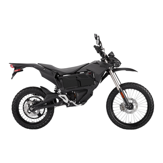
Page 28: Side View
Controls and Components Side View... - Page 29 Controls and Components A. Drive Belt I. Rear Brake Fluid Reservoir For description and operation, see “Drive Belt”, on For a description, see “Brake Fluid Level Inspection”, page 5-13. on page 5-9. B. Drive Belt Tension Adjuster For the drive belt adjustment procedure, see page 5-14.
-
Page 30: Dash Overview
Controls and Components Dash Overview... - Page 31 Controls and Components A. Adjust Button (ADJ) the rider using the performance level mode button located on the right handlebar control assembly. See See “Dash Settings”, on page 3-10. “Performance Level Mode Button”, on page 3-17 B. Select Button (SEL) I.
-
Page 32: Warning Indicator Lights
Controls and Components Warning Indicator Lights... - Page 33 Controls and Components A. Left Indicator Turn Signal E. Charging Indicator An arrow on the lower dash flashes green Flashes slowly when the motorcycle is in the same direction as selected by the accepting a charge. The indicator flashes turn signal switch. This arrow remains on rapidly when a charging error is detected.
-
Page 34: Dash Settings
Controls and Components Dash Settings Displays A&B Display A The displays on the dash can be customized to your personal preferences by using the ADJ (Adjust) and SEL To select Display A with the dash in its normal operating (Select) buttons. mode, momentarily press the SEL button once. - Page 35 Controls and Components Display B Setting the Clock To select Display B with the dash in its normal operating mode, momentarily press the SEL button twice. Press the ADJ button to toggle through the following fields: Trip 2 Odometer - Displays individual trip mileage and is reset by pressing and holding the ADJ button for 2 seconds.
- Page 36 Controls and Components Unit Display - Speed Unit Display - Temperature To change the units that the temperature display is shown: To change the units that speed is shown in: 1. With the dash in its normal operating mode press and 1.
-
Page 37: Smartphone Application
1. Ensure that the motorcycle is not Armed. The motorcycle must be keyed ON, the kickstand must be in Collect and email logs to Zero support staff the down position, and the run switch must be in the Examine the precise State of Charge (SOC) of your Stop position. -
Page 38: Handlebar Controls
Controls and Components Handlebar Controls 3.14... - Page 39 Controls and Components A. Flash-to-Pass braking feature activates. Regenerative braking takes some of the energy from the moving motorcycle and When the headlight is in the low beam position, push turns it back into electrical energy. This energy is then the flash-to-pass switch and the high beam illuminates stored back into the power pack, contributing to and stays illuminated until the switch is released.
- Page 40 Controls and Components E. Motor Stop Switch Always signal your turns and other maneuvers as required by law. Unlike an automobile, the turn signals When the top of the switch (A) is pressed, it cuts off must always be canceled manually on the motorcycle. power to the motor controller.
-
Page 41: Performance Level Mode Button
Controls and Components Performance Level Mode Button The SPORT selection causes the motorcycle to accelerate at a significantly faster rate. This position is recommended for advanced riders. The CUSTOM selection has customizable performance settings by using the smartphone application (refer to “Smartphone Application”, on page 3-13). - Page 42 Notes 3.18...
-
Page 43: Starting And Operating
The charge indicator should read fully charged. perform the following: 1. Remove the motorcycle from its shipping crate. See Unpacking Your Zero motorcycle on page 4-2. 2. You must charge the power pack before riding the motorcycle. Your Zero motorcycle is shipped fully charged from the factory. -
Page 44: Unpacking Your Zero Motorcycle
Carefully lift rear portion of the motorcycle over the Unpacking Your Zero Motorcycle swingarm standoff and off crate base. Although unpacking your Zero Motorcycle can be done by Carefully lift front wheel out of crate base. a single person, it is recommended to have a second ... -
Page 45: General Operation
Throttle. With the key switch in the OFF position, apply Pre-Ride Inspection the throttle and release to verify that the throttle is Before operating the Zero Motorcycle, check the following smooth and returns correctly. to make sure the motorcycle is secure and intact: ... -
Page 46: Key Switch/Steering Lock Positions
General Operation Key Switch/Steering Lock Positions Steering Lock Using the steering lock when parked will prevent unauthorized use and help prevent theft. To operate the steering lock: 1. Turn the handlebar all the way to the left. 2. Push the key down from the OFF position and turn the key counter-clockwise while still pushing it in. -
Page 47: Power Pack
The battery is located within the power pack and requires the electrical system. no special break in period. The 2014 Zero FX leverages the 2013’s new battery cell ON Position chemistry, configuration, and enhanced reliability. Not only This position is used for operating the motorcycle. In this does the Z-Force®... - Page 48 The BMS also monitors the power pack for a host of predefined conditions, and then takes actions according to WARNING! Opening of the power pack is for trained Zero those conditions. See “Battery Management System”, on Motorcycles technicians. Please be aware that incorrect page 6-6 and “Cold and Hot Weather Considerations”, on...
- Page 49 General Operation Power Pack Swapping 4. Using a firm grip, slide the power pack out of the frame. DO NOT lift the power pack by the plastic connector The motorcycles feature a quick change power pack. This housing. allows the rider to charge one power pack while using another.
-
Page 50: Power Pack Charger
90 days if stored fully charged. Zero recommends riding. you plug in your Zero Motorcycle after 30 days, even if fully If the power pack terminates the charge before the charged. Please leave your Zero Motorcycle plugged in charger reaches the state previously mentioned, then whenever possible. - Page 51 General Operation The on-board charger indicator (A) is visible on the dash panel. The charging indicator icon flashes while charging and is continuously lit when fully charged. For examples and information on Quick Charging LEDs see page 4-13. Charging Indicator Icon...
- Page 52 It is possible for lithium ion cells to overheat and fail. connector (see inset). Always keep the power cord with the motorcycle. Note: Charge the Zero Power pack in a location that is well-ventilated and away from combustible materials. If charging your Zero Motorcycle outdoors, avoid charging in the rain.
- Page 53 General Operation Note: AVOID connecting the Zero charger and another device to a single 120 V AC 15A/20A circuit, as it may become overloaded. Zero chargers draw as much as 12 amps from the 120 V AC circuit when charging.
- Page 54 General Operation To charge using the Quick Charger: 120 V AC or 240 V AC current. The voltage does not change the amount of time that the motorcycle takes to 1. Ensure that the key switch is in the OFF position. charge.
- Page 55 General Operation The BMS is cutting off the charge because one or Quick Charger LED Indicators more cells have reached maximum voltage. C. 100% Charge The 100% Charge LED is a green indicator. If it is on solid, the charging is complete and the off-board accessory charger will enter maintenance mode.
-
Page 56: Operating Your Motorcycle
Progressive use of the brakes should bring the Zero motorcycle to a complete stop without locking the wheels. Your Zero motorcycle is a light- 4.14... - Page 57 Please note that the lighting of this temperature indicator does not indicate that there’s anything malfunctioning with your Zero motorcycle; it is simply letting you know that the thermal strategy is working. If you do not moderate your speed/power, the bike’s system will reduce your speed/power until your Zero can maintain its maximum allowable thermal state;...
-
Page 58: Front Suspension Adjustment
General Operation Front Suspension Adjustment Rebound Damping The rebound damping is adjusted by turning the slotted A shock has two main actions: compression when the adjuster screw (B) on the top of both fork legs. Next to it shock gets loaded, and rebound when the shock returns will be the writing S-F, meaning Slow and Fast. - Page 59 General Operation Compression Damping will pack-up (feel harsh over consecutive bumps) while compression that is set too fast will cause the fork to The compression damping is adjusted by turning a screw bottom out harshly. on the bottom of each fork leg. There is a rubber dust cover protecting the jam nut (A) securing the screw (B).
-
Page 60: Rear Shock Adjustment
General Operation Rear Shock Adjustment Spring Adjustment Obtaining the correct rear spring preload is critical for proper handling. The spring preload must be set to match the weight of the rider. The spring is preloaded for an 180 lb (82 kg) rider. This puts the rear tire 1/3 of the way through its vertical travel. - Page 61 General Operation 9. Record this measurement, this will be measurement Example: MEASUREMENT OPERATOR VALUE 23.62 in (600 mm) 21.65 in (550 mm) 1.97 in (50 mm) The total sag (in example above) is 1.97 in (50 mm). The recommended total sag is 2.3 in to 2.9 in (69-76 mm). If the sag is not correct, the spring pre-load should be adjusted.
- Page 62 General Operation Spring Pre-load Adjustment 1. Clean any dirt or debris from the threads of the shock near the lock ring (A). 2. Using a lock ring wrench loosen the lock nut (A). 3. For measurements less than the specified value, decrease the pre-load on the spring by turning the spring nut (B) counter-clockwise on the shock.
- Page 63 General Operation Rebound Adjustment The rebound adjuster knob (A) is at the bottom of the shock. There are 12 clicks of rebound adjustment. The adjustment knob is located at the base of the shock. Printed on the knob is S-F, meaning Slow and Fast. The rebound adjuster knob controls how slow or fast the shock returns to its extended position after being compressed.
- Page 64 General Operation Compression Adjustment The compression adjustment knob is at the top of the shock. There are 16 clicks of compression adjustment. The knob has “+” (slower compression) and “-” (faster compression). Turn the adjuster clockwise for slower compression. ...
- Page 65 Factory Supplied Rear Suspension Settings The following information will allow you to adjust the rear suspension back to the factory settings the motorcycle was originally supplied with. FX Model ADJUSTMENT SETTING Rear Shock Compression 16 clicks out from fully closed...
- Page 66 Notes 4.24...
-
Page 67: Maintaining Your Motorcycle
Turn Signal Light Bulb (amber) RY10W (10 watt) motorcycle as detailed in this owner’s manual. Brake/Tail Lights Bulb 1157 (5 watt) Use only Zero approved parts and Zero Motorcycle Front Running Light Bulb W3W (3 watt) accessories. Brake Fluid DOT 4 ... -
Page 68: Maintenance Schedule
Maintenance Schedule The scheduled maintenance must be performed in accordance with this chart to keep your Zero motorcycle in top running condition. The initial maintenance is vitally important and must not be neglected. Where time and mileage are listed, follow the interval that occurs first. - Page 69 Maintaining Your Motorcycle ITEM ROUTINE EVERY INITIAL INITIAL ODOMETER MILEAGE READING RIDE 600 mi 4K mi 8K mi 12K mi 16K mi 20K mi (1K km) (7K km) (13K km) (19K km) (25K km) (31K km) 1 month 6 months 12 months 18 months 24 months...
- Page 70 Maintaining Your Motorcycle ITEM ROUTINE EVERY INITIAL INITIAL ODOMETER MILEAGE READING RIDE 600 mi 4K mi 8K mi 12K mi 16K mi 20K mi (1K km) (7K km) (13K km) (19K km) (25K km) (31K km) 1 month 6 months 12 months 18 months 24 months...
-
Page 71: Component Fasteners
Maintaining Your Motorcycle Component Fasteners Periodically check and tighten the following fasteners on your motorcycle. Torque Table LOCATION ITEM TORQUE NOTES Front axle end bolts 19 lb ft (26 Nm) Use LOCTITE® 242® (or equivalent) Handlebar clamp mount bolts 18 lb ft (24 Nm) Main pivot bolt/nut (swingarm) 75 lb ft (102 Nm) Use LOCTITE®... - Page 72 Maintaining Your Motorcycle Left Side Of Motorcycle Refer to Torque table on page 5-5.
- Page 73 Maintaining Your Motorcycle Right Side Of Motorcycle Refer to Torque table on page 5-5.
-
Page 74: Power Pack
The power pack must be charged within 24 hours if fully discharged, and charged within 90 days if stored fully charged. Please leave your Zero Motorcycle plugged in whenever possible. 1. The power pack is a lithium ion power system. While it does require charging, it does not require maintenance. -
Page 75: General Maintenance
General Maintenance Brakes Rear Brake Pads General Maintenance An example of the rear brake pads is shown below. This section describes how to inspect the brake fluid level for both the front and rear brakes. Your motorcycle uses specific brake pads for stopping power. Both front and rear pad examples are shown in the following sections. - Page 76 General Maintenance Front Brake Rear Brake Inspect the level of the front brake fluid through the sight glass (C). If the fluid level is visibly below the low level indicator (B), brake fluid must be added. Clean any dirt or debris from the cover (A) before opening the reservoir.
-
Page 77: Suspension
General Maintenance Suspension Brake Pad Inspection The brake pads must be inspected when specified in the Front maintenance schedule. See Maintenance Schedule For maintenance, see Maintenance Schedule on information on page 5-2. Visually inspect the brakes by page 5-2. looking at the remaining brake pad material through the ... -
Page 78: Wheels And Tires
General Maintenance Wheels and Tires Tire Inflation Inspect both wheels for the following: CAUTION: Under-inflation is a common cause of tire failure and may result in severe tire cracking, tread Bent, loose, or missing spokes separation, “blowout,” or unexpected loss of motorcycle ... -
Page 79: Drive Belt
General Maintenance Drive Belt Checking Drive Belt Tension Proper belt tension is essential for optimum operation of The drive belt provides low maintenance and quiet the drive system. operation with minimal stretch. Keep dirt, grease, oil, and Lack of belt tension can lead to “ratcheting.” The teeth of debris off the belt and sprockets. - Page 80 General Maintenance Drive Belt Adjustment Procedure Note: Adjust both sides equally. 1. Remove key from the key switch. 2. Loosen the rear axle nut (A). 3. Loosen the (left and right) 13 mm jam nuts (C). 4. Turn the (left and right) 13 mm adjustment bolts (B) 1/4 turn at a time until the belt adjustment is within specification.
-
Page 81: Drive Chain (Optional)
General Maintenance Drive Chain (Optional) 3. Using a brush, fill the bristles with spray from the chain cleaner. Begin gently scrubbing the chain on the top of Cleaning The Drive Chain your swingarm using the brush. CAUTION: Always wear safety glasses when cleaning the 4. - Page 82 General Maintenance Lubricating The Drive Chain Checking The Drive Chain CAUTION: Wear safety glasses when lubricating the chain 1. Remove the key from the key switch. to prevent eye injuries. 2. Using a ruler, grasp the chain halfway between the front and rear sprockets.
- Page 83 General Maintenance Adjusting The Drive Chain Note: Adjust both sides equally. 1. Remove key from the key switch. 2. Loosen the rear axle nut (A). 3. Loosen the (left and right) 13 mm jam nuts (C). 4. Turn the (left and right) 13 mm adjustment bolts (B) 1/4 turn at a time until the chain adjustment is within specification.
-
Page 84: Headlight Alignment
General Maintenance Headlight Alignment The headlight should be checked for correct alignment periodically. It must be aligned any time the suspension sag is adjusted because this will affect the headlight alignment. Before the headlight can be aligned, the suspension sag and tire pressure must be correctly adjusted. - Page 85 General Maintenance To replace the bulb: 5. Disconnect the headlight bulb connector (C). 6. Release the headlight bulb sealing boot (D). 1. Remove the two bolts (A) securing the trim cover above headlight assembly to the motorcycle. 2. Release and remove the trim cover. 3.
-
Page 86: Turn Signal Light Bulb Replacement
General Maintenance Turn Signal Light Bulb Replacement 7. Unhook the headlight bulb spring clip (E) by pushing down and to the side. To replace the signal light bulb: 1. Remove the turn signal lens screw (A) and remove the lens. 8. -
Page 87: Brake/Tail Light Bulb Replacement
General Maintenance Brake/Tail Light Bulb Replacement Running Light Bulb Replacement To replace the brake/trail light bulb: 1. Remove the two bolts (A) securing the trim cover above headlight assembly to the motorcycle. 1. Remove the brake/tail light lens screws (A) and remove 2. - Page 88 General Maintenance 5. Release the running light bulb retainer from headlight (C). 6. Remove the running light bulb from retainer. 7. Install the replacement running light bulb into retainer. 8. Installation is the reverse of the removal procedure. 5.22...
-
Page 89: Cleaning
General Maintenance Cleaning 1. Gently wash your motorcycle with a sponge or a clean soft cloth, mild detergent, and plenty of water. WARNING! Improper cleaning can damage electrical 2. Use care when cleaning the plastic parts (dash, components, cowling's, panels, and other plastic parts. Do fenders, and side panels), which can scratch easier not use high pressure water or steam cleaners;... -
Page 90: Parking And Long Term Storage
It is recommended to always leave the power pack Zero accessories are designed to complement and plugged in. The Zero charger is designed to maintain a function with other systems on your motorcycle. Your balanced and complete charge at all times without dealer can accessorize the motorcycle using genuine Zero wasting any electricity. - Page 91 General Maintenance 12 Volt Fuse Center To access the 12 volt fuse center: The 12 volt fuse center is located behind the front forks 1. Remove the left trim panel by removing 3 hex bolts, 1 under the left trim panel. standard bolt, and (push-in) plastic rivet.
- Page 92 General Maintenance High Voltage Fuse Center To replace a high voltage fuse: The high voltage fuse center is located on the left side of Unscrew the fuse cover. the motorcycle (in a cluster of five fuses). Replace the fuse. ...
-
Page 93: Service Record
Service Record Follow the maintenance schedules on page 5-2. After a scheduled service or routine is performed, record the information Service Record on the chart below. DATE ITEM SERVICE/ROUTINE DESCRIPTION 5.27... - Page 94 Notes 5.28...
-
Page 95: Troubleshooting
If you are unable to solve an for your safety. issue with your Zero FX Motorcycle, take it to an Do not touch, attempt to remove or replace any high authorized dealer at your convenience. If there is no dealer voltage parts, wiring (identified by the orange out sleeving) in your area call Zero Motorcycles Customer Service. -
Page 96: System Warning Indicator
Troubleshooting System Warning Indicator If a fault has been detected, count the number of times the red indicator light (A) flashes. Refer to the table on the following pages for a possible cause and solution to the issue. - Page 97 Motor Stop Switch Disabled or Kickstand motor stop switch ON button. Kickstand is down. Switch Disabled Raise kickstand. Indicator Always ON Contact Zero or your dealer. Self-Test Failed Unplug charger. Throttle is ON or throttle/connection is bad. Verify Charger Connected throttle action and/or check connection.
- Page 98 Zero or your dealer. Turn the ignition OFF and allow to cool off and then Temperature Protection Error restart. If problem persists contact Zero or your dealer. Turn the ignition OFF and ON. If problem persists Throttle Output Error contact Zero or your dealer.
-
Page 99: General Troubleshooting
Troubleshooting General Troubleshooting SYMPTOM POTENTIAL CAUSE POTENTIAL SOLUTION Motorcycle does not turn on Power Pack not charged. Key not properly engaged. Charge Power Pack. Recheck key in ignition, turn OFF/ON Motor stop switch turned OFF. Fault code set. again. Press the motor stop Switch ON button. See Understanding BMS Flash Code Patterns (Charge Mode) on page 6-8. -
Page 100: Battery Management System
Troubleshooting Battery Management System The Battery Management System (BMS) is located inside the power pack and is fitted with a window (A) to provide visual notification about the status of the power pack. There are four LED lamps that will flash: one red and three green lamps. - Page 101 50 ms 5 sec Healthy BMS OK 50 ms 5 ms Isolation Fault Contact Zero or the Dealer 50 ms 60 sec Pack Low Charge power pack 50 ms 1 sec Number of Cell Packs Not Set Contact Zero or the Dealer ...
- Page 102 Troubleshooting Understanding BMS Flash Code Patterns (Charge Mode) This mode is with the charging cord plugged into the AC power, and the key in the OFF position. During the Charging process, first all lights will flash. Next, lights 1 through 4 will flash depending on the power pack’s state of charge. 1 RED 2 GREEN 3 GREEN...
- Page 103 Troubleshooting Understanding BMS Flash Code Patterns (Run Mode) In this mode, the key is in the ON position. 1 RED 2 GREEN 3 GREEN 4 GREEN MEANING SOLUTION 5 sec 1 sec 25% of Power Remaining Charge Soon ...
- Page 104 Troubleshooting Power Pack Empty Power Pack Too Hot If the power pack is completely empty, an error-beep The power pack contains internal temperature sensors. If sounds and the BMS disables the throttle. You cannot ride the BMS measures excessive internal temperatures, it the motorcycle until you recharge the power pack.
- Page 105 Troubleshooting Other Error-Flash Patterns If the BMS in your power pack produces an error code which is not described in Understanding BMS Flash Code Patterns, then the power pack has encountered a serious internal hardware problem and must be repaired or replaced by a dealer.
-
Page 106: Cold And Hot Weather Considerations
Troubleshooting Cold and Hot Weather Considerations Storage of the motorcycle for the winter in a non-heated garage is acceptable, as long as: Cold Weather Operation 1. the coldest temperature in the garage does not fall Operation of the motorcycle in cold temperatures has no below -31°F (-35°C) permanent impact on its battery pack/cells;... - Page 107 Troubleshooting Hot Weather Operation Operation of the motorcycle in hot temperatures should not result in any noticeable performance changes. However, the BMS will not allow motorcycle operation and its associated battery discharge above 140°F (60°C), as measured at the battery. In hot temperatures greater than 110°F (43°C), the charger reduces its charge current to the battery, increasing charge time accordingly;...
-
Page 108: Safety Interlocks
Troubleshooting Safety Interlocks Throttle Disable Interlock The BMS communicates with the main motorcycle control If the BMS detects a serious internal fault, it can take either module. The BMS can send a signal to the main or both of two actions to prevent damage to the power motorcycle controller requesting that the throttle control on pack: the motorcycle be disabled. - Page 109 Troubleshooting Charger-Disable Interlock When the charger is attached and plugged in to AC power, the BMS communicates with the charger. The BMS can send a signal to the charger requesting that charging terminates immediately. When the charger is disabled, the indicator lights on the charger displays that charging has stopped.
- Page 110 Notes 6.16...
-
Page 111: Limited Warranty Information
Should a ZF2.8 Power Pack be purchased to upgrade the “in service date” for ZF2.8 Power Pack Modules on the capacity of a Zero FX ZF2.8 to ZF5.7 after the initial the Zero FX. “in service date” of the host Zero motorcycle, the Power ... -
Page 112: Who Does This Limited Warranty Cover
Limited Warranty Information Instead, the Power Pack’s outer case is covered for a Further, this Limited Warranty only covers 2014 Zero FX period of 2 years from its “in service date.” motorcycles or Power Packs that are operated according to “proper use” and “under normal operating conditions.”... - Page 113 Wheels on off-road bikes once they have been ridden parties or accessories that alter the motorcycle’s specifications from those set by Zero, or the use of new Any cosmetic concerns that arise as a result of or used parts not approved by Zero;...
-
Page 114: What Other Limitations Or Disclaimers Apply To This Limited Warranty
Warranty does not cover - and Zero cannot assume Zero does not assume – or authorize any person to responsibility for - any injury arising from the unsafe or assume – any other obligation or liability on its behalf. -
Page 115: What Are Your Responsibilities As A Customer
Packs, or parts that are covered by this Limited Warranty injury or death can result from improper operation or failure and found by Zero or an authorized Zero dealer to be to observe warnings and safety instructions on any defective in factory materials or workmanship. -
Page 116: How Do You Obtain Service Under This Limited Warranty
How Do You Obtain Service Under This Transfer Of Ownership And Warranty Limited Warranty? When it comes time to sell your Zero Motorcycle, please visit the Zero Motorcycles website and access the Owner Warranty services may be obtained by contacting your Resources section to fill out the on-line transfer of local Zero Motorcycle dealer. -
Page 117: Customer Information
Washington, DC 20590 E-mail: support@zeromotorcycles.com (24 hours) You can also obtain other information about motor vehicle For 24 hour updates and additional information about your safety from: motorcycle, visit the Owner Resources section of the Zero http://www.safercar.gov Motorcycles website: www.zeromotorcycles.com/owner- resources/... - Page 118 Notes...
- Page 119 Index Drive Chain ..............5.15 Adjustment Procedure..........5.17 Accessories ..............5.24 Cleaning ..............5.15 Lubricating...............5.16 Bolt Torque Specifications..........5.5 Brake/Tail Light Bulb Replacement ......5.21 Emissions Information ..........1.12 Brakes ................5.9 Brake Fluid Level Inspection ........5.9 Brake Pad Inspection ..........5.11 First Time Set-Up............4.1 DOT 4 brake fluid ............5.10 Fuses ................5.24 Front Brake .............5.10 High Voltage Fuse Center........5.26...
- Page 120 Index Pre-Ride..............4.3 Plug in Your Z-Force Power Pack......1.2 Instrument Panel ............3.6 Serial Number ............1.4 Pre-Ride Inspection ............4.3 Public Charging Stations ..........1.9 Keys Replacement Code Number ........1.4 Quick Charging............4.11 Location Of Important Labels ........2.3 Reporting safety defects..........
- Page 121 Understanding Your VIN Number ......1.5 Front (Factory) ............4.17 Vehicle Range ...............1.8 Rear (Factory) ............4.23 VIN.................1.4 Technical Specifications Warning Lights............3.6 Zero FX Technical Specifications......1.6 Warranty Temperature Indicator Coverage..............7.1 Power Pack Full (High Power Pack-Voltage)..6.10 Exclusions ..............7.2 Tire Inflation..............5.12 Transfer Of Ownership And Warranty .......7.6 Transporting ..............1.13...
- Page 122 Notes INDEX.4...
- Page 123 First Responder Information - High Voltage Components Locations...
- Page 124 TAKE CHARGE ™ WWW.ZEROMOTORCYCLES.COM...
Need help?
Do you have a question about the 2014 FX and is the answer not in the manual?
Questions and answers