Acer ICONIA TAB A200 Service Manual
Hide thumbs
Also See for ICONIA TAB A200:
- User manual (58 pages) ,
- User manual (59 pages) ,
- User manual (58 pages)
Table of Contents
Advertisement
Quick Links
Advertisement
Table of Contents

Related Manuals for Acer ICONIA TAB A200


Summary of Contents for Acer ICONIA TAB A200
- Page 1 ICONIA TAB A200 S E R V I C E G U I D E G U I D E...
-
Page 2: Table Of Contents
Table of Contents Chapter 1. Hardware Specifications and Configurations Features ............1-2 Tablet tour. - Page 3 ICONIA TAB A200 ........
-
Page 4: Revision History
Updates Copyright Copyright © 2011 by Acer Incorporated. All rights reserved. No part of this publication may be reproduced, transmitted, transcribed, stored in a retrieval system, or translated into any language or computer language, in any form or by any means, electronic, mechanical, magnetic, optical, chemical, manual or otherwise, without the prior written permission of Acer Incorporated. - Page 5 Conventions The following conventions are used in this manual: WARNING: Indicates a potential for personal injury. CAUTION: Indicates a potential loss of data or damage to equipment. IMPORTANT: Indicates information that is important to know for the proper completion of a procedure, choice of an option, or completing a task.
- Page 6 For Acer-authorized service providers: Your Acer office may have a different part number code than those given in the FRU list of this printed service guide. The list provided by your regional Acer office must be used to order FRU...
- Page 7 CHAPTER Hardware Specifications and Configurations Hardware Specifications and Configurations ....1-2 Features ............1-2 Tablet tour .
-
Page 8: Chapter 1. Hardware Specifications And Configurations
Hardware Specifications and Configurations Features The following is a summary of the computer’s many features: Form Factor • 10.1” Tablet Operating System • Android Honeycomb Platform • Tegra 250 Dual Cortex A9, 1GHz ® • Ultra Low Power GeForce System Memory •... -
Page 9: Expansion Slot
Connectivity Wi-Fi • IEEE 802.11 b/g/n Bluetooth ® • Bluetooth 2.1+EDR • Micro USB 2.0 Type B for Client • USB 2.0 Host GPS/A-GPS • Wi-Fi SKU: Broadcom - stand alone, A-GPS not supported Expansion Slot • MicroSD memory card up to 32G (SDHC 2.0 compatible) Input •... -
Page 10: Green Requirement
Others • Reset hole Green Requirement • Rohs compliance • WEEE compliance • Halogen free, at least PVC free • SMT Green process Accessory In Box • USB cable • Charger + Plug • NOTE: Protective film is not included. Optional •... -
Page 11: Tablet Tour
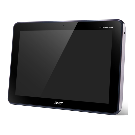
Tablet tour Front View Figure 1:1. Front View Item Description Camera A 2-megapixel camera for video chatting and self-portrait images. Touch Screen 10.1-inch, 1280 x 800 capacitive touch screen. Hardware Specifications and Configurations... -
Page 12: Rear View
Rear View Figure 1:2. Rear View Item Description Speakers Emits stereo audio. Hardware Specifications and Configurations... -
Page 13: Top View
Top View Figure 1:3. Top View Icon Item Description Screen Rotation Use this switch to lock the screen rotation or allow the Lock Switch screen to match the tablet’s orientation. Volume Control Increases or decreases the tablet volume. Hardware Specifications and Configurations... -
Page 14: Left View
Left View Figure 1:4. Left View Icon Item Description • Long press to turn the tablet on. • Press briefly to turn the screen on/off or enter sleep Power Button mode. • Press and hold to turn the tablet off. Headset Jack Connects to stereo headphones. -
Page 15: Right View
Right View Figure 1:5. Right View Icon Item Description AC Adapter Jack Connects to the power adapter. Hardware Specifications and Configurations... -
Page 16: System Block Diagram
System Block Diagram Figure 1:6. System Block Diagram 1-10 Hardware Specifications and Configurations... -
Page 17: Specifications Table
Specifications Table Computer specifications Item Metric Imperial Dimensions Length 260 mm 10.23 in Width 175 mm 6.89 in Height (front to rear) 12.4 mm 0.489 in Weight (equipped with optical Under 650g for Wi-Fi SKU Under 1.432 lbs drive, flash drive, and battery) Weight (equipped with optical drive, flash drive, and without battery) - Page 18 ULPI Phy for USB Bluetooth AW-NH611 Wireless AW-NH611 BCM4751IFBG GPS Low-Noise Amplifier MAX2659ELT+ TOUCH controller mXT768E eMMC 8G/16G (Base on Acer’s AVL) CAMERA Aptina SOC 2031, 2M pixel Thermal Sensor NCT1008CMT3R2G Audio codec WM8903LGEFK-RV Audio Amplifier ALC105-GR Echo Cancellation FM2018WE-380...
- Page 19 Processor Item Specification ® Dual-core ARM Cortex-A9 MPCore™ Processor Up to 1 GHz CPU package 664-ball FCBGA, 23 x 23 mm, 0.8 mm pitch NOTE: No CPU Fan in this product. Processor Specifications Bus Speed Cach Core Item Cores Mfg Tech Package Speed (FSB/DMI/QBI)
- Page 20 Hard Disk Drive Interface Item Specification Kingston Kingston SanDisk SanDisk Vendor & KE44B-26BN/ KE44B-26BN/ SDIN5C1-16G SDIN5C2-8G Model Name 16GB Capacity (GB) DC Power Requirements VCC: 2.85V Voltage tolerance VCCQ: 1.8V Audio Codec Interface Item Specification Audio Controller WM8903LGEFK-GV Audio onboard or optional On board Mono or Stereo Stereo...
- Page 21 Audio Amplifier IC Item Specification Amplifier IC ALC105-GR • Single-Ended stereo analog input • BTL (Bridge-Tied Load) output provides up to 3W per channel driving capability into 4Ω speaker load (5V power is supplied) • No external output L-C filter required •...
- Page 22 Item Specification Viewing Angle (degree) Horizontal (Right) CR = 10 Min.: 80 (Right) / 80 (Left) / 80 (Upper) / 80 (Lower) (Left) Typ: 85 (Right) / 85 (Left) / 85 (Upper) / 85 (Lower) Vertical (Upper) CR = 10 (Lower) No LCD Inverter for this product Display Supported Resolution (GPU Supported Resolution)
- Page 23 Wireless Module 802.11b/g/n Item Specification Chipset AW-NH611 SIP (include Broadcom BCM4329) 802.11b: 1, 2, 5.5, 11Mbps Data throughput 802.11g: 6, 9, 12, 18, 24, 36, 48, 54Mbps 802.11n:MCS 0~7 Protocol IEEE 802.11b/g/n, Wi-Fi compliant Interface SDIO/SPI Connector type I-PEX Supported protocol CCXv2/CCXv3/CCXv4/CCXv5, WFAEC Bluetooth Module Item...
- Page 24 Video Interface Item Specification Chipset N/A (Graphic function is embedded in CPU) Package Interface Compatibility Sampling rate VRAM Item Specification Chipset Memory size Interface USB Port Item Specification USB compliance level USB2.0 Modes Host & Device Speed Low, Full and High Number of USB port(s) 2 ports (1 port for Host, 1 port for Device) Location...
- Page 25 AC Adapter Item Specification Total output power 0.5A(RMS)Max. @120Vac Maximum input AC current 0.25A(RMS)Max. @240Vac 40A Max. for 120VAC at Max load Inrush current 60A Max. for 240VAC at Max load (At cold start) Efficiency Meet EPA 2.0 System Power Management Item Specification Mech.
- Page 26 MicroSD Card Reader Item Specification Chipset SD function is supported by CPU. Package Interface SDIO Maximum supported size Follow up SD card spec Features Storage cards with adapter: microSD™ System LED Indicator Item Specification • White color solid on: System on System state •...
- Page 27 Hardware IRQ System Function IRQ5* IRQ6 IRQ7* IRQ8 IRQ9* IRQ10* IRQ11 IRQ12 IRQ13 IRQ14 IRQ15 NOTE: Default configuration; audio possible configurations are IRQ5, IRQ7, IRQ9, IRQ10, or none. NOTE: ExpressCards may assert IRQ3, IRQ4, IRQ5, IRQ7, IRQ9, IRQ10, IRQ11, or IRQ15. Either the infrared or the serial port may assert IRQ3 or IRQ4.
- Page 28 I/O Address (hex) System Function (Shipping Configuration) 065 - 06F 070 - 071 072 - 07F 080 - 08F 090 - 091 093 - 09F 0A0 - 0A1 I/O Address (hex) 0A2 - 0BF 0C0 - 0DF 0E0 - 0EF 0F0 - 0F1 0F2 - 0FF 100 - 16F...
- Page 29 I/O Address (hex) System Function (Shipping Configuration) 2A0 - 2A7 2A8 - 2E7 2E8 - 2EF 2F0 - 2F7 2F8 - 2FF 300 - 31F 320 - 36F 370 - 377 378 - 37F 380 - 387 388 - 38B 38C - 3AF 3B0 - 3BB 3BC - 3BF...
- Page 30 CHAPTER Diagnostic Utilities Diagnostic Utilities ........2-2 Introduction .
-
Page 31: Chapter 2. Diagnostic Utilities
Diagnostic Utilities Introduction The ICONIA TAB A200 has a software tool designed to diagnose problems with its hardware components. Diagnostic Tool SOP Preparation • Diagnostic Tool - ACTP.zip • USB Driver of A200 for PC • USB cable • MicroSD card Tool Installation Install the USB driver in PC/NB. - Page 32 Run “Install QCJ00.bat”. Figure 2:2. ACTP Folder Directory On the device, go to the applications screen and look for the diagnostic tool named “ACTP”. Figure 2:3. Device Applications Screen Tap the ACTP icon to start the testing process. (Figure 2:3) Diagnostic Utilities...
-
Page 33: Main Menu
Main Menu The diagnostic tool tests the Touch Panel, Display, Buttons, Speaker, Microphone, Camera, SD card and Vibrator functionality. Select the function(s) you want to test. Tap OK to start. Step 1 – Select item(s) Step 2 – Click “ O K” to star t tes t ing Figure 2:4. - Page 34 2. Touch Linearity Test (Touch Panel) Draw your finger along the yellow squares. The result is a “Pass” if you fill all the yellow squares and a “Fail” if you do not. The program returns to the main menu after the test is finished. Figure 2:6.
-
Page 35: Front Camera
4. Hardware Keys Test (Keys) Press the volume up, volume down and lock keys to verify if all keys work. A color change to green means key function works. Figure 2:8. Hardware Keys Test 5. Front Camera Aim the front side of the device at an object. Tap the “Photograph” icon to test the picture taking functionality. - Page 36 6. Speakers Loud tone sounds in the left speaker and then switches to the right speaker. Figure 2:10. Speakers Test 7. Front Microphone Tap the screen to start the test. When the “Recording” screen appears, speak into the device. Check if the voice is recorded when the screen switches to the “Playing” screen. Figure 2:11.
- Page 37 8. SD Card (SD Read/Write Test) Insert a microSD card into the device. Start the SD read and write test. The screen shows success if the test is passed. Figure 2:12. SD Card Test 9. Vibrator The device starts vibrating three times every half a second and then displays the final screen as below.
-
Page 38: Uninstallation Procedures
Uninstallation Procedures The diagnostic tool MUST be uninstalled once testing is done. IMPORTANT: DO NOT distribute this tool outside of the service center. On the device, go to the applications screen. Touch and hold the “ACTP” icon and drag it to the “Uninstall”... - Page 39 The “Uninstall finished” message appears when the process is complete. Figure 2:16. Uninstall Finished Diagnostic Utilities 2-10...
- Page 40 CHAPTER Service and Maintenance Service and Maintenance ....... . . 3-2 Introduction .
-
Page 41: Chapter 3. Service And Maintenance
Service and Maintenance Introduction This chapter contains general information about the tablet, a list of tools needed to perform the required maintenance and step by step procedures on how to remove and install components from the tablet computer. Recommended Equipment The following tools are required to perform maintenance on the tablet: •... -
Page 42: Maintenance Flowchart
Maintenance Flowchart The flowchart in Figure3-1 provides a graphic representation of the module removal and installation sequences. It provides information on what components need to be removed and installed during servicing Lower Case DC-in Cable Battery Wifi / Bluetooth Speaker LVDS cable Mainboard Antenna... -
Page 43: Getting Started
Getting Started The flowchart (Figure 3:1, page 3-3) identifies sections illustrating the entire removal and installation sequence. Observe the order of the sequence to avoid damage to any of the hardware components. Perform the following prior to performing any maintenance procedures: Place the system on a flat work surface. -
Page 44: Sd Card Removal
SD Card Removal Open the SD card cover. Figure 3:3. Opening the SD Card Cover Push the SD card to eject it from the slot, and then remove the card. Figure 3:4. Removing the SD Card Service and Maintenance... - Page 45 Secure the SD card cover. Figure 3:5. Securing the SD Card Cover Service and Maintenance...
-
Page 46: Sd Card Installation
SD Card Installation Open the SD card cover. (Figure 3:3, page 3-5) Push the SD card into the slot until it clicks into place. Figure 3:6. Installing the SD Card Close the SD card cover. (Figure 3:5, page 3-6) Service and Maintenance... -
Page 47: Lower Case Removal
Lower Case Removal Prerequisite: SD Card Removal on page Open the SD card cover. Figure 3:7. Opening the SD Card Cover Insert the pointed plastic pry into the slot next to the SD card cover to unlock the latch. Figure 3:8. Unlocking the Left IO Cover Latches (1 of 4) Service and Maintenance... - Page 48 Starting from the edge shown in Figure 3-8, release the latches from the bezel with your hands. Figure 3:9. Unlocking the Left IO Cover Latches (2 of 4) Insert the plastic pry into the slot to unlock the lower latch. Figure 3:10.
- Page 49 Release the latches from the bezel with your hands. Figure 3:11. Unlocking the Left IO Cover Latches (4 of 4) Insert the plastic pry into the gap between the AC adapter jack and the right IO cover, and then pry to unlock the right IO cover latch. Figure 3:12.
- Page 50 Release the latches from the bezel with your hands. Figure 3:13. Unlocking the Right IO Cover Latches (2 of 2) Remove the screws from the bezel. Figure 3:14. Removing the Screws 3-11 Service and Maintenance...
- Page 51 Release the top side of the lower case from the latches of the bezel. Figure 3:15. Releasing the Side Latches (1 of 4) Release the bottom side of the lower case from the latches of the bezel. Figure 3:16. Releasing the Side Latches (2 of 4) Service and Maintenance 3-12...
- Page 52 Release the right side of the lower case from the latches of the bezel. Figure 3:17. Releasing the Side Latches (3 of 4) Remove the lower case from the bezel. Figure 3:18. Releasing the Side Latches (4 of 4) 3-13 Service and Maintenance...
-
Page 53: Lower Case Installation
Lower Case Installation Make sure the Lock key on the lower case (A) and the Lock key on the bezel (B) are on the same direction. Figure 3:19. Checking the Lock Key Position Align the left edge of the lower case with the connectors slot on the bezel. Figure 3:20. - Page 54 Using the plastic pry, slightly push the right side of the lower case to secure the right side of the bezel. Figure 3:21. Installing the Lower Case (2 of 4) Secure all sides of the lower case to the latches on the bezel. Figure 3:22.
- Page 55 Install and secure the screws to the bezel. Figure 3:23. Installing the Lower Case (4 of 4) Install and secure the right IO cover to the bezel latches. Figure 3:24. Installing the Right IO Cover Service and Maintenance 3-16...
- Page 56 Install and secure the lower left IO cover to the bezel latches. Figure 3:25. Installing the Left IO Cover (1 of 2) Install and secure the upper left IO cover to the bezel latches. Figure 3:26. Installing the Left IO Cover (2 of 2) 3-17 Service and Maintenance...
- Page 57 Close the SD card cover. Figure 3:27. Closing the SD Card Cover Table 3:1. Lower Case Screws Screw Name Screw Type Quantity M 2.0 x 4.0 Ni Service and Maintenance 3-18...
-
Page 58: Dc-In Cable Removal
DC-In Cable Removal Prerequisite Lower Case Removal on page Remove the protective tape covering the DC-In cable. Figure 3:28. Removing the Protective Tape Disconnect the DC-In cable from the mainboard connector. Figure 3:29. Disconnecting the DC-In Cable 3-19 Service and Maintenance... - Page 59 Pull to detach the cable with adhesive (C) and the DC-In jack (D) from the slot on the bezel. Figure 3:30. Removing the DC-In Cable Service and Maintenance 3-20...
-
Page 60: Dc-In Cable Installation
DC-In Cable Installation Install the DC-In cable jack and the cable adhesive. Figure 3:31. Installing the DC-In Cable (1 of 3) Connect the DC-In cable to the mainboard connector. Figure 3:32. Installing the DC-In Cable (2 of 3) 3-21 Service and Maintenance... - Page 61 Install and secure the protective tape covering the DC-In cable. Figure 3:33. Installing the DC-In Cable (3 of 3) Install the lower case (see Lower Case Installation on page 3-14). Service and Maintenance 3-22...
-
Page 62: Battery Removal
Battery Removal Prerequisite: DC-In Cable Removal on page 3-19 Disconnect the battery cable from the mainboard connector. Figure 3:34. Disconnecting the Battery Cable Remove the screws securing the battery to the mainboard and the bezel. Figure 3:35. Removing the Battery Screws 3-23 Service and Maintenance... - Page 63 Remove the battery. Figure 3:36. Removing the Battery Service and Maintenance 3-24...
-
Page 64: Battery Installation
Battery Installation Install the battery on the bezel. Figure 3:37. Installing the Battery Secure the screws to the bezel and the mainboard. Figure 3:38. Attaching the Battery Screws 3-25 Service and Maintenance... - Page 65 Connect the battery connector to the mainboard connector, and insert the cables into the gap between the mainboard and the battery. Figure 3:39. Connecting the Battery Cable Install the DC-In cable (see DC-In Cable Installation on page 3-21). Table 3:2. Battery Screws Screw Name Screw Type Quantity...
-
Page 66: Speaker Removal
Speaker Removal Prerequisite: Battery Removal on page 3-23 Remove the protective tape covering the LVDS cable. Figure 3:40. Removing the LVDS Protective Tape Remove the protective tape covering the speakers and the touch panel control cables. Figure 3:41. Removing the Cables Protective Tape 3-27 Service and Maintenance... - Page 67 Disconnect the speakers connector from the mainboard connector (A). Figure 3:42. Disconnecting the Speakers and Touch Module Cables Disconnect the touch module cable (B) and release the speakers cable from the guides. (Figure 3:41) CAUTION: The touch module cable may be damaged when folded. Do not fold the touch module cable. Remove the screws (C, D) from the bezel.
-
Page 68: Speaker Installation
Speaker Installation Install the speakers (A) and secure the screws (B, C) on the bezel. Figure 3:44. Installing the Speakers Route the speakers cable with the guides on the bezel. Figure 3:45. Routing the Speakers Cable 3-29 Service and Maintenance... - Page 69 Connect the touch module cable connector (D). Figure 3:46. Connecting the Cable Connectors Connect the Speakers cable connector (E) to the mainboard. (Figure 3:46) Secure the protective tape covering the speakers and the touch panel control cables. Figure 3:47. Attaching the Cables Protective Tape Service and Maintenance 3-30...
- Page 70 Secure the protective tape covering the LVDS cable. Figure 3:48. Attaching the LVDS Protective Tape Install the battery (see Battery Installation on page 3-25). Table 3:3. Speakers Screws Screw Name Screw Type Quantity M 2.0 x 4.0 Ni M 2.0 x 3.0 3-31 Service and Maintenance...
-
Page 71: Touch Panel Control Cable Removal
Touch Panel Control Cable Removal Prerequisite: Battery Removal on page 3-23 Remove the protective tape covering the LVDS cable. Figure 3:49. Removing the LVDS Protective Tape Remove the protective tape covering the speakers and the touch panel control cables. Figure 3:50. Removing the Cables Protective Tape Service and Maintenance 3-32... - Page 72 Disconnect the touch panel control cable connectors. Figure 3:51. Disconnecting the Touch Panel Control Cable Connectors 3-33 Service and Maintenance...
-
Page 73: Touch Panel Control Cable Installation
Touch Panel Control Cable Installation Connect the touch panel control cable connectors. Figure 3:52. Connecting the Touch Panel Control Cable Connectors Secure the protective tape covering the speakers and the touch panel control cables. Figure 3:53. Attaching the Cables Protective Tape Service and Maintenance 3-34... - Page 74 Secure the protective tape covering the LVDS cable. Figure 3:54. Attaching the LVDS Protective Tape Install the battery (see Battery Installation on page 3-25). 3-35 Service and Maintenance...
-
Page 75: Lvds Cable Removal
LVDS Cable Removal Prerequisite: Battery Removal on page 3-23 Remove the protective tape covering the LVDS cable. Figure 3:55. Removing the LVDS Protective Tape Disconnect the LVDS cable connector from the mainboard connector. Figure 3:56. Disconnecting the LVDS Cable (1 of 2) Service and Maintenance 3-36... - Page 76 Disconnect the LVDS cable connector from the LCD panel connector. Figure 3:57. Disconnecting the LVDS Cable (2 of 2) 3-37 Service and Maintenance...
-
Page 77: Lvds Cable Installation
LVDS Cable Installation Connect the LVDS cable connector to the LCD panel connector. Figure 3:58. Connecting the LVDS Cable (1 of 2) Connect the LVDS cable connector to the mainboard connector. Figure 3:59. Connecting the LVDS Cable (2 of 2) Service and Maintenance 3-38... - Page 78 Secure the protective tape to cover the LVDS cable. Figure 3:60. Attaching the LVDS Cable Protective Tape Install the battery (see Battery Installation on page 3-25). 3-39 Service and Maintenance...
-
Page 79: Microphone Removal
Microphone Removal Prerequisite: Battery Removal on page 3-23 Disconnect the microphone cable connector from the mainboard connector. Figure 3:61. Disconnecting the Microphone Connector Remove the microphone from slot on the bezel. Figure 3:62. Removing the Microphone Service and Maintenance 3-40... -
Page 80: Microphone Installation
Microphone Installation Install the microphone to the microphone slot of the bezel. Figure 3:63. Installing the Microphone Connect the microphone cable connector to the mainboard connector. Figure 3:64. Connecting the Microphone Cable Connector Install the battery (see Battery Installation on page 3-25). 3-41 Service and Maintenance... -
Page 81: Wlan Antenna Removal
WLAN Antenna Removal Prerequisite: Battery Removal on page 3-23 Disconnect the WLAN antenna connector from the mainboard connector. Figure 3:65. Disconnecting the WLAN Antenna Remove the metallic tape securing the WLAN antenna to the bezel. Figure 3:66. Removing the Metallic Tape Service and Maintenance 3-42... - Page 82 Remove the WLAN antenna. Figure 3:67. Removing the WLAN Antenna 3-43 Service and Maintenance...
-
Page 83: Wlan Antenna Installation
WLAN Antenna Installation Align the WLAN antenna to the antenna slot on the bezel. Figure 3:68. Installing the WLAN Antenna (1 of 3) Attach the metallic tape to secure the WLAN antenna to the bezel. Figure 3:69. Installing the WLAN Antenna (2 of 3) Service and Maintenance 3-44... - Page 84 Connect the WLAN antenna connector to the mainboard connector. Figure 3:70. Installing the WLAN Antenna (3 of 3) Install the battery (see Battery Installation on page 3-25). 3-45 Service and Maintenance...
-
Page 85: Gps Antenna Removal
GPS Antenna Removal Prerequisite: Battery Removal on page 3-23 Disconnect the GPS antenna connector from the mainboard connector. Figure 3:71. Disconnecting the GPS Antenna Remove the adhesive tape securing the GPS antenna cable to the mainboard. Figure 3:72. Removing the Cable Adhesive Tape Service and Maintenance 3-46... - Page 86 Remove the metallic tape securing the GPS antenna to the mainboard. Figure 3:73. Removing the Antenna Metallic Tape Remove the GPS antenna from the bezel. Figure 3:74. Removing the GPS Antenna 3-47 Service and Maintenance...
-
Page 87: Gps Antenna Installation
GPS Antenna Installation Align the GPS antenna to the antenna slot on the bezel. Figure 3:75. Installing the GPS Antenna (1 of 4) Attach the metallic tape to secure the GPS antenna to the mainboard. Figure 3:76. Installing the GPS Antenna (2 of 4) Service and Maintenance 3-48... - Page 88 Attach the adhesive tape to secure the GPS antenna cable to the mainboard. Figure 3:77. Installing the GPS Antenna (3 of 4) Connect the GPS antenna connector to the mainboard connector. Figure 3:78. Installing the GPS Antenna (4 of 4) Install the battery (see Battery Installation on page 3-25).
-
Page 89: Mainboard Removal
Mainboard Removal Prerequisite: Battery Removal on page 3-23 Disconnect the following cables from the mainboard connectors: • LVDS cable connector (A) • Speaker cable connector (B) • Touch panel control cable connector (C) • Microphone connector (D) • WLAN antenna cable connector (E) Figure 3:79. - Page 90 Disconnect the GPS antenna cable (F). (Figure 3:79, page 3-50) If the GPS antenna needs replacement, perform the procedures in GPS Antenna Removal on page 3-46. If the GPS antenna does not need a replacement, do not detach the metallic tape securing the GPS antenna to the mainboard.
- Page 91 Remove the screws securing the mainboard from the bezel. Figure 3:82. Removing the Mainboard Screws Slowly lift the mainboard from the outer edge, and detach the camera cable connector from the mainboard. Figure 3:83. Removing the Mainboard Remove the mainboard from the bezel. Service and Maintenance 3-52...
-
Page 92: Mainboard Installation
Mainboard Installation Connect the camera cable connector to the mainboard connector. Figure 3:84. Disconnecting the Camera Cable Align the mainboard to the bezel guides and install and secure the mainboard screws. Figure 3:85. Securing the Mainboard Screws 3-53 Service and Maintenance... - Page 93 Connect the following cables: • LVDS cable connector (A) • Speaker cable connector (B) • Touch panel control cable connector (C) • Microphone connector (D) • WLAN antenna cable connector (E) • GPS antenna cable connector (F) Figure 3:86. Mainboard Screws Install the battery (see Battery Installation on page 3-25)
-
Page 94: Front Camera Removal
Front Camera Removal Prerequisite: Mainboard Removal on page 3-50 Remove the camera from the camera slot on the bezel. Figure 3:87. Removing the Front Camera 3-55 Service and Maintenance... -
Page 95: Front Camera Installation
Front Camera Installation Connect the camera cable connector to the mainboard connector. Figure 3:88. Connecting the Camera Cable Install the camera to the camera slot on the bezel. Figure 3:89. Installing the Camera Install the mainboard (see Mainboard Installation on page 3-53). Service and Maintenance 3-56... - Page 96 CHAPTER Troubleshooting Troubleshooting .........4-2 General Information .
-
Page 97: General Information
NOTE: The diagnostic tests are intended to test only Acer products. Non-Acer products, prototype cards, or modified options can give false errors and invalid system responses. Obtain as much detail as possible about the problem. -
Page 98: Power On Issues
Power On Issues If the system does not power on, perform the following: Start Check AC cable / BATT Swap AC cable / BATT only power on Swap M/B Figure 4:1. Power On Issues Troubleshooting... -
Page 99: No Display Issues
No Display Issues If the system does not display, perform the following: Start Go to no power power on Trouble shooting step Swap LCD cable Check LCD cable Swap LCD panel LCD panel Swap M/B Figure 4:2. No Display Issues Troubleshooting... -
Page 100: Lcd Picture Failure
LCD Picture Failure If the LCD picture fails, perform the following: Start Swap LCD cable Check LCD cable Swap LCD panel Check LCD panel Swap M/B Figure 4:3. LCD Picture Failure Troubleshooting... -
Page 101: Touch Screen Failure
Touch Screen Failure If the touch screen fails, perform the following: Start Check touch Swap touch screen cable screen cable Check touch Swap touch screen small/B screen small/B Check touch Swap touch screen panel screen panel Swap M/B Figure 4:4. Touch Screen Failure Troubleshooting... -
Page 102: Internal Speaker Failure
Internal Speaker Failure If the internal speakers fail, perform the following: Start Swap SPK Check SPK Swap M/B Figure 4:5. Internal Speaker Failure Troubleshooting... -
Page 103: Internal Microphone Failure
Internal Microphone Failure If the internal microphone fails, perform the following: Start Check the front MIC and the back MIC Swap the Swap the Check the Check the front MIC front MIC back MIC back MIC Swap M/B Swap M/B Figure 4:6. -
Page 104: Usb Failure
USB Failure If the USB fails, perform the following: Start Swap the USB/B Check the USB/B to M/B FFC to M/B FFC Swap the USB/B Check the USB/B Swap M/B Figure 4:7. USB Failure Troubleshooting... -
Page 105: Front Camera Failure
Front Camera Failure If the front camera fails, perform the following: Start Swap the Check the front camera front camera Swap M/B Figure 4:8. Front Camera Failure Troubleshooting 4-10... -
Page 106: Wireless Function Test Failure
Wireless Function Test Failure If the wireless function fails, perform the following: Start Swap the Check the antenna W/L antenna Swap M/B Figure 4:9. Wireless Function Test Failure 4-11 Troubleshooting... -
Page 107: Gps Function Test Failure
GPS Function Test Failure If the GPS function fails, perform the following: Start Swap the Check the antenna GPS antenna Swap M/B Figure 4:10. GPS Function Test Failure Troubleshooting 4-12... -
Page 108: Other Functions Failure
Other Functions Failure Check the component connection to the mainboard. To test for mainboard fault, swap mainboard. 4-13 Troubleshooting... - Page 109 CHAPTER Jumper and Connectors Location Jumper and Connector Locations ......5-2 Mainboard Top View ..........5-2 Mainboard Bottom View .
-
Page 110: Chapter 5. Jumper And Connector Locations
Jumper and Connector Locations Mainboard Top View SW3 SW5 LED3 JLINE1 JP70 JP72 Figure 5:1. Mainboard Top Table 5:1. Mainboard Top Jumper and Connectors Item Description Item Description SW2, SW3 Volume Key JP70 Debug Connector Lock Key JP72 USB Connector Power Button MicroSD connector LED3... -
Page 111: Mainboard Bottom View
Mainboard Bottom View ANT5 JP14 ANT3 JMIC3 PJP3 PJP2 JLVDS3 JP58 JP55 Figure 5:2. Mainboard Bottom Table 5:2. Mainboard Bottom Jumper and Connectors Item Description Item Description ANT5 Wi-Fi Antenna JLVDS3 Panel Connector Touch Panel Control JP14 2M Camera Connector JP58 Connector JMIC3... - Page 112 CHAPTER Field Replaceable Unit List FRU (Field Replaceable Unit) List ......6-2 Exploded Diagram ..........6-3 FRU List .
-
Page 113: Chapter 6. Fru (Field Replaceable Unit) List
FRU (Field Replaceable Unit) List This chapter provides the FRU (Field Replaceable Unit) listing in global configurations for the ICONIA TAB A200. Refer to this chapter whenever ordering for parts to repair or for RMA (Return Merchandise Authorization). NOTE: When ordering FRU parts, check the most up-to-date information available on the regional web or channel. -
Page 114: Exploded Diagram
Exploded Diagram Figure 6:1. Main Assembly Exploded Diagram FRU (Field Replaceable Unit) List... - Page 115 Table 6:1. Main Assembly Exploded Diagram Description Acer P/N LCD TOUCH MODULE INCL. 6M.H8Q02.001 CONTROL BOARD and LVDS CABLE BATTERY BT.00203.011 MAINBOARD MB.H8P00.001 MICROPHONE 23.H8Q02.001 ANTENNA GPS 50.H8Q02.004 TOUCH CONTROL BOARD CABLE 50.H8Q02.002 SPEAKER L+R 23.H8Q02.002 LEFT IO COVER UP 42.H8Q02.002...
-
Page 116: Fru List
FRU List CATEGORY Description Part No. ADAPTER Adapter PHIHONG 18W 12V/1.5A Black PSA18R- AP.0180P.002 120P(AI)-R LF Adapter PHIHONG 18W 12V/1.5A 1.1x3.0x7.5 AP.0180P.003 Black PSA18R-120P(AI)-R, w/i 150cm cable LF BATTERY Battery SANYO BAT-1012 Polymer 2S1P SANYO BT.00203.011 2 Cell 3260mAh Main COMMON CABLE DC-IN CABLE 50.H8Q02.001... - Page 117 6M.H8Q02.001 CONTROL BOARD & LVDS CABLE DIGITAL LIGHT DEVICE CAMERA 2M 57.H8Q02.001 MAINBOARD OT_HH • Acer A200 Mainboard 8G eMMC MB.H8P00.001 A200_8ti, A200_8r Nvidia Tegra 250 OT_HH • Acer A200 Mainboard 16G eMMC MB.H8Q00.001 A200_16ti, A200_16r Nvidia Tegra 250 SPEAKER 23.H8Q02.001...
-
Page 118: Screw List
CATEGORY Description Part No. MISCELLANEOUS 2M CAMERA SPONGE 47.H8Q02.001 Screw List CATEGORY Description Part No. SCREWS SCREW 2.0D 3.0L K 3.6D ZK NL CR3 86.H8Q02.001 SCREW 2D 4.0L K 4.0D NI NL 0.3T 86.H8Q02.002 FRU (Field Replaceable Unit) List... - Page 119 ICONIA TAB A200 ........
-
Page 120: Chapter 7. Model Definition And Configuration
Model Definition and Configuration ICONIA TAB A200 Table 7:1. RO, NS and Description Model Country Part No. Description A200 Tablet None WW_GEN1 A200 AU/NZ XE.H8PAN.001 AndroidAU-Tab-1 A200 AU- Titanium N Wi-Fi only_8G N N A200 Tablet None WW_GEN1 A200 AU/NZ XE.H8XAN.003... - Page 121 Table 7:1. RO, NS and Description Model Country Part No. Description A200 Tablet PA_CA AndroidCA-Tab-1 A200 Canada XE.H8WPN.003 US- Red 8G N N N A200 Tablet PA_CUS1 AndroidUSA- A200 XE.H8WPN.002 Tab-1 US- Red 8G N N N A200 Tablet WW_GEN1 AndroidLatin- A200 Argentina XE.H8WPN.005...
- Page 122 Table 7:1. RO, NS and Description Model Country Part No. Description A200 Tablet None WW_GEN1 A200 West EU-1 XE.H8WEN.005 AndroidWEU_Tab_WW EUEU Red 8G N N N A200 Tablet None WW_GEN1 A200 West EU-1 XE.H8PEN.005 AndroidWEU_Tab_WW EUEU Titanium 8G N N N A200 Tablet None EMEA_CUS2 A200 Belgium...
- Page 123 Table 7:1. RO, NS and Description Model Country Part No. Description A200 Tablet None WW_GEN1 Eastern A200 XE.H8XEN.006 AndroidEE-Tab-2 EUEU Red 16G N N Europe Eastern A200 Tablet None WW_GEN1 A200 XE.H8WEN.006 Europe AndroidEE-Tab-2 EUEU Red 8G N N N A200 Tablet None WW_GEN1 Eastern A200...
- Page 124 Table 7:1. RO, NS and Description Model Country Part No. Description A200 Tablet None WW_GEN1 A200 Japan XE.H8WAN.002 AndroidJP-Tab-A200 US- Red 8G N N A200 Tablet None WW_GEN1 A200 Japan XE.H8PAN.002 AndroidJP-Tab-A200 US- Titanium 8G N N N A200 Tablet None WW_GEN1 A200 Middle East XE.H8XEN.007...
- Page 125 Table 7:2. BOM Name, CPU and LCD Model Country Part No. BOM Name ACLA- A200 XE.H8QPN.004 A200_16ti NV-TEGRA250 H10.1WXGA w/TP Spanish ACLA- A200 XE.H8WPN.001 A200_8r NV-TEGRA250 H10.1WXGA w/TP Spanish ACLA- A200 XE.H8PPN.001 A200_8ti NV-TEGRA250 H10.1WXGA w/TP Spanish A200 XE.H8WWN.001 A200_8r NV-TEGRA250 H10.1WXGA w/TP A200...
- Page 126 Table 7:2. BOM Name, CPU and LCD Model Country Part No. BOM Name Belgium A200 XE.H8QEN.005 A200_16ti NV-TEGRA250 H10.1WXGA w/TP Belgium A200 XE.H8WEN.004 A200_8r NV-TEGRA250 H10.1WXGA w/TP Belgium A200 XE.H8PEN.004 A200_8ti NV-TEGRA250 H10.1WXGA w/TP Nordic A200 XE.H8QEN.009 A200_16ti NV-TEGRA250 H10.1WXGA w/TP A200 XE.H8QEN.007 A200_16ti...
- Page 127 Table 7:2. BOM Name, CPU and LCD Model Country Part No. BOM Name Japan A200 XE.H8WAN.002 A200_8r NV-TEGRA250 H10.1WXGA w/TP Japan A200 XE.H8PAN.002 A200_8ti NV-TEGRA250 H10.1WXGA w/TP Middle East A200 XE.H8XEN.007 A200_16r NV-TEGRA250 H10.1WXGA w/TP Middle East A200 XE.H8WEN.007 A200_8r NV-TEGRA250 H10.1WXGA w/TP Middle East...
- Page 128 Table 7:3. Memory1, Memory2 and Memory3 Model Country Part No. Memory1 Memory2 Memory3 A200 XE.H8PPN.005 MDDR8GbII eMMC8GB A200 Canada XE.H8WPN.003 MDDR8GbII eMMC8GB A200 XE.H8WPN.002 MDDR8GbII eMMC8GB A200 Argentina XE.H8WPN.005 MDDR8GbII eMMC8GB A200 Mexico XE.H8WPN.004 MDDR8GbII eMMC8GB A200 Canada XE.H8XPN.001 MDDR8GbII eMMC16GB A200 Mexico...
- Page 129 Table 7:3. Memory1, Memory2 and Memory3 Model Country Part No. Memory1 Memory2 Memory3 A200 Japan XE.H8QAN.001 MDDR8GbII eMMC16GB Eastern A200 XE.H8XEN.006 MDDR8GbII eMMC16GB Europe Eastern A200 XE.H8WEN.006 MDDR8GbII eMMC8GB Europe Eastern A200 XE.H8PEN.006 MDDR8GbII eMMC8GB Europe A200 France XE.H8XEN.003 MDDR8GbII eMMC16GB A200 France...
- Page 130 Table 7:4. Front Camera, Battery and Adapter Model Country Part No. Front Camera Battery Adapter Chicony 2M FF AP2031 A200 AU/NZ XE.H8PAN.001 2CELL3.26 sensor Chicony 2M FF AP2031 A200 AU/NZ XE.H8XAN.003 2CELL3.26 sensor Chicony 2M FF AP2031 A200 AU/NZ XE.H8WAN.003 2CELL3.26 sensor Chicony 2M FF AP2031...
- Page 131 Table 7:4. Front Camera, Battery and Adapter Model Country Part No. Front Camera Battery Adapter Chicony 2M FF AP2031 A200 Mexico XE.H8XPN.002 2CELL3.26 sensor Chicony 2M FF AP2031 A200 XE.H8XPN.003 2CELL3.26 sensor Chicony 2M FF AP2031 A200 Argentina XE.H8XPN.004 2CELL3.26 sensor Chicony 2M FF AP2031 A200...
- Page 132 Table 7:4. Front Camera, Battery and Adapter Model Country Part No. Front Camera Battery Adapter Chicony 2M FF AP2031 A200 France XE.H8QEN.006 2CELL3.26 sensor Chicony 2M FF AP2031 A200 Middle East XE.H8QEN.004 2CELL3.26 sensor Eastern Chicony 2M FF AP2031 A200 XE.H8QEN.003 2CELL3.26 Europe...
- Page 133 Table 7:4. Front Camera, Battery and Adapter Model Country Part No. Front Camera Battery Adapter Chicony 2M FF AP2031 A200 Nordic XE.H8WEN.008 2CELL3.26 sensor Chicony 2M FF AP2031 A200 Nordic XE.H8PEN.009 2CELL3.26 sensor Chicony 2M FF AP2031 A200 Japan XE.H8XAN.002 2CELL3.26 sensor Chicony 2M FF AP2031...
- Page 134 Table 7:5. Communication, Wi-Fi Module and Color Model Country Part No. Communication Wi-Fi Module Color ACLA- WiFi AZURE AW-NH611 Titanium A200 XE.H8QPN.004 Spanish ACLA- WiFi AZURE AW-NH611 A200 XE.H8WPN.001 Spanish ACLA- WiFi AZURE AW-NH611 Titanium A200 XE.H8PPN.001 Spanish A200 XE.H8WWN.001 WiFi AZURE AW-NH611 A200...
- Page 135 Table 7:5. Communication, Wi-Fi Module and Color Model Country Part No. Communication Wi-Fi Module Color A200 Belgium XE.H8QEN.005 WiFi AZURE AW-NH611 Titanium A200 Belgium XE.H8WEN.004 WiFi AZURE AW-NH611 A200 Belgium XE.H8PEN.004 WiFi AZURE AW-NH611 Titanium A200 Nordic XE.H8QEN.009 WiFi AZURE AW-NH611 Titanium A200 XE.H8QEN.007...
- Page 136 Table 7:5. Communication, Wi-Fi Module and Color Model Country Part No. Communication Wi-Fi Module Color A200 Japan XE.H8WAN.002 WiFi AZURE AW-NH611 A200 Japan XE.H8PAN.002 WiFi AZURE AW-NH611 Titanium A200 Middle East XE.H8XEN.007 WiFi AZURE AW-NH611 A200 Middle East XE.H8WEN.007 WiFi AZURE AW-NH611 A200 Middle East...
- Page 137 Table 7:6. Panel Size, Resolution and Form Factor Panel Model Country Part No. Panel Size Form Factor Resolution A200 Argentina XE.H8PPN.004 10.1" WXGA Bar-type A200 XE.H8PPN.005 10.1" WXGA Bar-type A200 Canada XE.H8WPN.003 10.1" WXGA Bar-type A200 XE.H8WPN.002 10.1" WXGA Bar-type A200 Argentina XE.H8WPN.005...
- Page 138 Table 7:6. Panel Size, Resolution and Form Factor Panel Model Country Part No. Panel Size Form Factor Resolution Eastern 10.1" WXGA Bar-type A200 XE.H8QEN.003 Europe Eastern 10.1" WXGA Bar-type A200 XE.H8QEN.002 Europe A200 Germany XE.H8QEN.001 10.1" WXGA Bar-type A200 Japan XE.H8QAN.001 10.1"...
- Page 139 Table 7:6. Panel Size, Resolution and Form Factor Panel Model Country Part No. Panel Size Form Factor Resolution Eastern 10.1" WXGA Bar-type A200 XE.H8WEN.009 Europe Eastern 10.1" WXGA Bar-type A200 XE.H8PEN.008 Europe A200 S7.H8XWN.001 10.1" WXGA Bar-type A200 S7.H8WWN.001 10.1" WXGA Bar-type Model Definition and Configuration...
- Page 140 CHAPTER Test Compatible Components Test Compatible Components ......8-2 Android OS Environment Test ........8-2...
-
Page 141: Chapter 8. Test Compatible Components
Test Compatible Components This computer’s compatibility is tested and verified by Acer’s internal testing department. All of its system functions are tested under Android OS environment. Refer to the following lists for components, adapter cards, and peripherals which have passed these tests. - Page 142 Bluetooth FM AW-NH611 802.11bgn QF.11N0Z.002_ Azurewave_ NH611_ single band_ Battery Battery SANYO BAT-1012 Polymer 60001921 2CELL3.26_ 2S1P SANYO 2 Cell 3260mAh Main BT.00203.011_ SANYO_ COMMON_ Accessory 10001012 Micro USB Acer Micro USB cable Micro USB XZ.70200.115 COMPAL_ cable_ cable_Picasso/VanGogh_ Test Compatible Components...
- Page 143 CHAPTER Online Support Information Online Support Information ....... .9-2 Introduction ........... . 9-2...
-
Page 144: Chapter 9. Online Support Information
This section describes online technical support services available to help users repair their Acer Systems. For distributors, dealers, ASP or TPM, please refer the technical queries to a local Acer branch office. Acer Branch Offices and Regional Business Units may access our website. However some information sources will require a user i.d.
Need help?
Do you have a question about the ICONIA TAB A200 and is the answer not in the manual?
Questions and answers