Table of Contents
Advertisement
Quick Links
Advertisement
Table of Contents

Related Manuals for Satlink FB150

Summary of Contents for Satlink FB150
-
Page 2: Warranty
Satlink S.L. shall not be liable for errors contained herein. The information in this document is subject to change without notice. Satlink S.L. makes no warranty of any kind with regard to this material, including, but not limited to, the implied warranties of merchantability and fitness for a particular purpose. -
Page 3: Regulatory Information
Satlink FB150 System User Guide Regulatory Information Federal Communication Commission Notice USE CONDITIONS: This device complies with part 15 of the FCC Rules. Operation is subject to the following two Conditions: 1. This device may not cause harmful interference, and 2. -
Page 4: Industry Canada Statement
Satlink FB150 System User Guide Industry Canada Statement: This device complies with Radio standard specification RSS -170 of Industry Canada Rules. Operation is subject to the following two conditions: 1. This device may not cause harmful interference, and 2. This device must accept any interference received, including interference that may cause undesired operation. -
Page 5: Safety Summary
For the sake of safety and protection, please read the user guide before you attempt to use the Satlink FB150 FleetBroadband System. In particular, read this safety section carefully. Keep this safety information where you can refer to it if necessary. - Page 6 Ship’s Power Supply The input voltage for Satlink FB150 FleetBroadband System is 12V DC, 8A or 24V DC, 4A. It is recommended to use 24V DC power line, provided that it is available on the ship.
- Page 7 Satlink FB150 System User Guide Information in this document is subject to change without notice and does not represent a commitment on the part of Satlink S.L. Copyright © 2009 Satlink S.L. All rights reserved. Website: www.satlink.es 3 3 3 3...
-
Page 8: Chapter 1 - Introduction
- achieving greater operational efficiencies and significantly reducing the cost of both business and crew communications. Listed is the range of services available for the Satlink FB150 User Equipment: Email and webmail... -
Page 9: Main Units
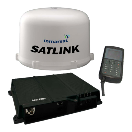
Primary Handset • Satlink FB150 FleetBroadband ADU (Above Deck Unit) The Satlink FB150 ADU is a medium size, maritime FleetBroadband Class 14, 3-axis marine antenna. The antenna is self-tracking based on patented beam squint technology. The simple and robust electromechanical system, with one motor per free axis, provides full coverage in azimuth and elevation. - Page 10 The BDU has been developed for maximum flexibility and is the controlling unit for the Satlink FB150 FleetBroadband UE. It features a reliable industry standard interfacing field and enables users to have optimal connectivity no matter what the conditions or your position at sea.
- Page 11 Satlink FB150 System User Guide SIM Card Slot The BDU has a SIM (Subscriber Identity Module) card slot located at the connector panel behind a small cover plate. The UE requires a dedicated FleetBroadband SIM card to access the FleetBroadband network and configure the settings of the UE.
- Page 12 Satlink FB150 System User Guide The Primary Handset’s RJ45 connector is plugged into the BDU’s primary handset port and it is powered directly from the BDU. For information on how to use the handset, see Chapter 3, Using the Primary Handset.
-
Page 13: Chapter 2 - Getting Started
Chapter 2 – Getting Started Before proceeding on getting started on the Satlink FB150 BDU, the information of how to install Satlink FB150 system and the connection of the cables can refer to Chapters 6 and 7 of this user guide. - Page 14 Satlink FB150 System User’s Guide 5. Use your finger to push the SIM card gently until it is being clicked and locked in place. Any screwdriver can be helped to push the SIM card if the SIM card cannot be inserted properly.
- Page 15 Satlink FB150 System User’s Guide Note: It's important that the antenna cable is connected properly to the Satlink FB150 ADU and BDU. Check to ensure that the antenna cable connectors are securely and properly connected. Connecting to DC Power Source Follow these steps to connect the Satlink FB150 BDU to the ship’s power source:...
- Page 16 4. Tighten screw on the connection stopper to ensure that the Primary Handset’s connector is securely connected to Primary Handset Port on the front panel. Powering Up Satlink FB150 BDU Follow these steps to power ON the Satlink FB150 1. Tip down the Power Switch on the front panel. Power Switch Alternatively.
- Page 17 Identification Number : 4 to 8 digits) is provided together with it. Note: You will need to enter the PIN at start-up if the Satlink FB150 BDU has been powered down. Follow these steps to enter the SIM PIN: 1. Using the keypad on the Primary Handset, enter the SIM PIN.
- Page 18 Satlink FB150 System User’s Guide To make a call from an analog phone (optional) connected to the Satlink FB150 BDU’s Phone port, off-hook the phone and dial, 00 <country code> <phone number> followed by the key. Sending the first SMS (Message) Follow these steps to send the first SMS: 1.
- Page 19 IP address and a DNS server address automatically. Follow these steps to connect a computer to the Satlink FB150 BDU: 1. Connect your LAN cable between the network connector on your computer and the first LAN port on the Satlink FB150 BDU.
- Page 20 5. Type in admin in the Username field and wideye in the Password field. Click OK. The Satlink FB150 Web Console will open. The Terminal will proceed automatically to “Checking PIN status” followed by “Antenna pointing” and then registering to the network (upon power on).
- Page 21 Satlink FB150 System User’s Guide Follow these steps to disconnect the data connection: 1. Click Disconnect ( ) to deactivated the PDP context. The PDP context will be deactivated.
-
Page 22: Chapter 3 - Using The Primary Handset
Satlink FB150 System User Guide Chapter 3 – Using the Primary Handset The Primary Handset The Primary Handset is connected to the BDU using the dedicated HANDSET port and is powered directly from the UE. Equipped with a large 1.5’, 65K CSTN, 128 x 128 dots Liquid... -
Page 23: Powering Up The Primary Handset
Satlink FB150 System User Guide Powering Up the Primary Handset The Primary Handset is automatically powered up once it is connected to the dedicated HANDSET port. Depending on the conditions of the UE, the Primary Handset may start in the following modes:... - Page 24 Satlink FB150 System User Guide Primary Handset Keypad 1. Earpiece 2. Display 3. Ear-set jack 4. OK key 5. 4-way navigation ring 6. Select key (Left) 7. Select key (Right) 8. Call/Answer key 9. Call/Menu End key 10. Keypad (Alpha-numeric) 11.
-
Page 25: Keypad - Description And Functions
Satlink FB150 System User Guide Keypad - Description and Functions Keys Description/Functions 4-way navigation ring. Press the 4-way navigation ring to scroll left, right, up, and down on the display. Enables scrolling through names, phone numbers, menus or settings. OK key. - Page 26 Satlink FB150 System User Guide Keys Description/Functions Star When entering a phone number, press this key to insert a Press and hold this key to insert a +. When writing text, press this key to access a list of special symbols.
- Page 27 Satlink FB150 System User Guide The Main Display Screen UE Status Indicator Line Primary Handset Status Indicator Selection Key Line UE Status Indicator line • The indicator line shows status symbols informing you about the operating conditions of the UE.
- Page 28 Satlink FB150 System User Guide Primary Handset Status Indicators Table below explains the meaning of each status indicator displayed in the Main Display screen. Status Indicator Description New short message (SMS) in inbox. Available PS domain services. Available CS domain services.
- Page 29 Satlink FB150 System User Guide Making a Voice Call Note: Before making a voice call, please make sure that: The Primary Handset is connected to the UE ( status indicator should be The UE has successfully registered with the network and ready for CS domain...
-
Page 30: Adjusting Volume During A Call
Satlink FB150 System User Guide Adjusting volume during a call Use the 4-way navigation ring to adjust the volume. Press ‘down’ key to Press ‘up’ key to decrease the volume increase the volume... - Page 31 Satlink FB150 System User Guide Using the Menus You can access the Menu System by pressing the Right selection key in the Main Display screen. The main menu of the Primary Handset includes nine (9) menu options with each menu option having their respective sub-menus.
-
Page 32: Contacts Menu
Satlink FB150 System User Guide Contacts Menu The Contacts menu allows you to store, retrieve and update names and phone numbers of your contacts in the Primary Handset memory and in the SIM card memory. You can also access this menu by pressing Left selection key in Main Display screen. - Page 33 Satlink FB150 System User Guide Note: You can also delete the selected contact by pressing the Clear key. Copy • Select this to copy the selected contact from SIM card memory to UE memory or vice versa. View number •...
- Page 34 Satlink FB150 System User Guide Log Menu The Log menu allows you to view historical information about phone calls and data usage in chronological order with the following sub menus: Missed calls Received calls Dialled calls Call history of the particular category is displayed in chronological order when selected. Up to 5 latest entries of each category can be saved.
- Page 35 Satlink FB150 System User Guide Select this to clear the call log entries. Available log options are: Missed calls • Received calls • Dialled calls • All calls • Delete all logs including Missed, Received and Dialled logs. Call/Data usage Display the accumulated call and data duration.
-
Page 36: Telephony Menu
Satlink FB150 System User Guide Telephony Menu The Telephony menu allows you to configure telephony related settings with the following sub menus: Speed dial Setting • Contain options to enable/disable the speed dial feature Speed Dial List • Select this to configure the speed dial list.The following options are available when... - Page 37 Satlink FB150 System User Guide You can also make a voice call to the number of the selected entry by pressing the Call key. You can make a voice call directly from the Main Display screen by pressing the corresponding speed dial entry number + Call key once the speed dial feature is enabled with a valid contact entry.
- Page 38 Satlink FB150 System User Guide Data Menu The Data menu provides the following sub menus to manage and configure data connections (PDP profiles) for the UE: Manage profiles Allow you to mange the Primary PDP profiles. One Standard Primary PDP profile has been created in the profile list as a default profile.
- Page 39 Satlink FB150 System User Guide Username: Specify the user name for Static IP configuration. Default is blank for Dynamic IP configuration. Password: Specify the password for Static IP configuration. Default is blank for Dynamic IP configuration. You can press the Left...
- Page 40 Satlink FB150 System User Guide To active a primary data connection when there is no active connection: 1. From the data status list, select Options using the Left selection key. 2. Select Activate primary using Left selection key or key.
-
Page 41: Messaging Menu
Satlink FB150 System User Guide Messaging Menu The Messaging menu allows the user to write a new messages, view stored messages from Inbox, Drafts and/or Sent folders and configure settings related to SMS with the following sub menus: New Message Select this to create and send a new message. - Page 42 Satlink FB150 System User Guide o <123>: Numbers o <abc>: Small letters o <Abc>: Initial Capital letter followed by small letters To add a number in alphabet mode, press and hold the desired number key. • Inserting symbols to your message: To get a list of special symbols, press the .key.
- Page 43 Satlink FB150 System User Guide Make a voice call to the selected message sender. Save • Save the selected message into the Draft folder. Details • Display the details of the selected message. Add to contact • Select this to add the phone number of the selected message into the contact list.
- Page 44 Satlink FB150 System User Guide Open • Open selected message. You can also press while browsing through the message list to open the selected message (This option is not available when viewing the message). Delete • Delete selected message. Note: You can also delete the selected message by pressing the Clear key.
-
Page 45: Settings Menu
Satlink FB150 System User Guide Settings Menu The Settings menu provides the following sub menus to configure the Ciphering mode Contain options to enable/disable the use of ciphering mode between the network and UE. Note: Status icon is displayed in the Main Display screen when ciphering is enabled. - Page 46 Satlink FB150 System User Guide Except for DHCP server, the rest of the display settings can be edited by pressing the Left selection or keys. Note: Make sure that the format is correct when entering an IP address. Press the Star key multiple times to insert the “.”(dot) sign.
- Page 47 Satlink FB150 System User Guide No answer Calls are forwarded when no answer from the UE for a specific time. Not reachable Calls are forwarded when UE is not reachable. You can press the Left selection key for options available when browsing through the list of forwarding conditions.
- Page 48 SatlinkSatlink FB150 System User Guide Call barring • Allow you to configure for call barring services depending on various barring conditions. The following conditions are available for activations/deactivations by pressing the key: Outgoing calls Barring of all outgoing calls. Incoming calls Barring of all incoming calls.
- Page 49 Satlink FB150 System User Guide Update • Update configured settings to the network Note: Always use Retrieve option to retrieve the latest settings from the network. Use Update option to update the network settings after configurations. Caller ID • Allow you to configure settings that are related to caller identifications.
-
Page 50: Terminal Menu
Satlink FB150 System User Guide Terminal Menu The Terminal menu provides the following sub menus to check for information and perform resets on the UE: Signal strength Show graphical representation of current signal strength and GPS type. Table below describes the available GPS type icons used in this sub menu:... - Page 51 Satlink FB150 System User Guide Serial number Serial number of the UE ADU Info Display a list of information of the Antenna. Serial number Serial number of the Antenna Terminal restart Soft restarting the UE Limited reset Perform limited reset on the UE. Apart from full factory reset that is not available in Primary Handset, limited reset only resets a small portion of the UE settings.
-
Page 52: Security Settings Menu
Satlink FB150 System User Guide Security settings Menu The Security Settings menu provides the following sub menus to configure the security settings of the UE using different PIN: Terminal PIN SIM PIN SIM PIN2 SIM lock Service provider Corporate There are three options available for selection under each sub menus to manage the PIN... - Page 53 Satlink FB150 System User Guide SIM lock 000000 Service provider Depends on your SIM card. Consult your equipment distributor if necessary. Corporate Depends on your SIM card. Consult your equipment distributor if necessary. You will be asked to key in the existing PIN (or default PIN if it has not been changed) before the PIN can be enabled.
- Page 54 Satlink FB150 System User Guide Phone manager Menu The Phone manager menu provides the following sub menus to configure settings that are local to the Primary Handset: Display Configure settings that are related to Primary Handset display. Backlight • Used to set the duration of the display backlight to remain on. Settings range from Always On (Backlight permanently on), 15 seconds to 1 minute.
- Page 55 Satlink FB150 System User Guide Configure the volume of the ring tone. Using the 4-way navigation ring , press up/right to increase and down/left to decrease the volume. Language Allow you to change the menu display language. Factory settings Allow you to configure default factory settings of the Primary Handset. Contains the following...
-
Page 56: Chapter 4 - Using The Web Console
Satlink FB150 System User’s Guide Chapter 4 – Using the Web Console 1. Connect your computer to the Satlink FB150 UE using a LAN cable. 2. When the connection has been established, open the web browser. 3. Type http://192.168.1.35 in the Address field and press Enter. - Page 57 Satlink FB150 System User’s Guide...
- Page 58 Satlink FB150 System User’s Guide Chapter 4 – Using the Web Console 1. Connect your computer to the Satlink FB150 UE using a LAN cable. 2. When the connection has been established, open the web browser. 3. Type http://192.168.1.35 in the Address field and press Enter.
- Page 59 Satlink FB150 System User’s Guide Setup Menu Viewing Terminal Information 1. Click 2. Click Terminal Info to view the Satlink FB150 UE terminal information. The terminal information is displayed according to the Satellite Tracking mode. Signal Indicates the received signal strength.
- Page 60 Satlink FB150 System User’s Guide Indicates the latitude, longitude, type and time of the GPS acquisition. Pointing Angle Indicates the azimuth and elevation angle of the ADU antenna with the corresponding satellite in view. Satellite Selection The default Satellite Selection is in Auto mode. In Auto mode, the UE will scan all the visible satellites and track the satellite with the most optimum elevation angle or the last used satellite.
- Page 61 Satlink FB150 System User’s Guide 3. Click on your choice of visible satellites. 4. Click Select to point the antenna to the selected satellite in exclusive mode. The satellite selection will be saved and each time you power up the UE, the satellite selection choice will remain until you make the next selection change.
- Page 62 Satlink FB150 System User’s Guide Setup Menu Viewing Terminal Information 1. Click 2. Click Terminal Info to view the Satlink FB150 UE terminal information. The terminal information is displayed according to the Satellite Tracking mode. Signal Indicates the received signal strength.
- Page 63 The View option allows you to view the Phonebook entries from the different storage locations. From the drop-down menu, select: To view the entries stored in the SIM card and FB150 UE. SIM only To view the entries stored in the SIM card.
- Page 64 Satlink FB150 System User’s Guide Deleting a Phonebook entry Follow these steps to delete a Phonebook entry: 1. Select the entry from the Phonebook list. 2. Click Delete. 3. Click Ok to confirm to delete the entry. Click Cancel to abort delete.
- Page 65 Satlink FB150 System User’s Guide View option • The View option allows you to view the Call History entries. From the drop-down menu, select: To view the list of the dialed, received and missed calls. Dialed Call To view the list of dialed calls only.
- Page 66 Satlink FB150 System User’s Guide 3. Type in the text message and click Send. Deleting a Call History entry Follow these steps to delete a Call History entry: 1. Select the entry from the Call History list. 2. Click Delete.
- Page 67 Satlink FB150 System User’s Guide Composing A New Message Follow these steps to compose a new SMS: 1. Enter the receiver’s phone number in the Phone no. field or click the Phonebook icon if the receiver’s number is listed in the Phonebook...
- Page 68 Satlink FB150 System User’s Guide Note: Message is limited to 160 characters including spacing between words. For sending SMS to another BGAN terminal, the message is limited to 608 characters including spacing between words. 3. Uncheck Store a copy in SIM checkbox if you do not wish to store a copy of the sent SMS into SIM card.
- Page 69 Satlink FB150 System User’s Guide Forwarding an SMS Follow these steps to forward an SMS: 1. Click on a SMS to select it. The selected SMS will be highlighted in light blue. 2. Click Forward. The Inbox console switches over to the Compose console.
- Page 70 Satlink FB150 System User’s Guide Resending a sent SMS Follow these steps to resend a sent SMS (sending the same SMS to the same receiver): 1. Click on a SMS to select it. 2. Click Resend. The SMS will be sent to the recipient.
- Page 71 Satlink FB150 System User’s Guide 3. Enter the receiver’s number in the Phone No. field. 4. Click Send. The SMS will be sent to the recipient. Deleting a SMS from the Sent list Follow these steps to delete a single SMS from the Sent list: 1.
- Page 72 Satlink FB150 System User’s Guide Follow these steps to send a draft SMS: 1. Click on a SMS to select it. 2. Click Send. The SMS will be sent to the recipient. Forwarding a draft SMS to another recipient Follow these steps to forward a draft SMS to another recipient: 1.
- Page 73 Satlink FB150 System User’s Guide 3. Enter the receiver’s number in the Phone No. field. 4. Click Send to forward the SMS. The SMS will be forwarded to the recipient. Deleting a SMS from the Draft list Follow these steps to delete a SMS from the Draft list: 1.
- Page 74 Satlink FB150 System User’s Guide Connection To activate the default profile, click Activate Default Profile. The PDP context will be activated. When connected, APN and the assigned public IP Address details will be displayed. You can proceed to access the Internet and use the related features.
- Page 75 Satlink FB150 System User’s Guide Primary Profiles Primary profiles define the connection type. You can select from a list of profiles to be the default primary profile and connection type. From Profile 2 to Profile 10, you can create your own customized primary profile.
-
Page 76: Port Forwarding
2. Check the Header Compression checkbox if it is required to use Header Compression. Port Forwarding Port Forwarding is a feature for Router (multiple-user) mode. This feature sets the Satlink FB150 UE to direct incoming traffic on certain TCP/UDP port to a specific port on a local PC (IP Address). - Page 77 3. Click Update to allow the selection to take effect. Click Refresh to query the current mode. • Settings Menu Click the following tabs to view and edit the configuration settings for the Satlink FB150 UE: Language • Terminal Info •...
-
Page 78: Terminal Info
Satlink FB150 System User’s Guide Support • Language Select the desired language for the Web Console to be displayed. (Spanish, Chinese-Simplified and Chinese-Traditional may not be an option that is available at the time of purchase). Terminal Info This tab shows general information about the UE, Error/Event Logs and Call Logs. - Page 79 Satlink FB150 System User’s Guide Logs • Displays event and error logs of the UE. Call Logs • Displays the call history including standard voice calls, high-quality/fax calls, standard data sessions and streaming data sessions.
- Page 80 Satlink FB150 System User’s Guide Ethernet Ethernet • 1. Click Ethernet to view and edit the Ethernet settings. 2. Click Update to allow the settings to take effect. DHCP • 1. Click DHCP to view and edit the DHCP settings.
- Page 81 Satlink FB150 System User’s Guide Mac Address Filtering • 1. Click Mac Filtering to view and edit the Mac Filtering settings. 2. Click Update to allow the settings to take effect. Reject List • All PCs/Laptops will be allowed to access the UE except for those (MAC addresses) listed in the Reject List.
- Page 82 Satlink FB150 System User’s Guide 1. Select European Caller Line ID Phone connected or US Caller Line ID Phone connected from the Telephone Interface Configuration drop-down menu. 2. Click Update to allow the setting to take effect. • Caller ID 1.
- Page 83 Satlink FB150 System User’s Guide • Call Barring 1. Click any individual Retrieve option to get the current setting of the corresponding scenario in which the calls would be barred. 2. Select the scenario in which the calls would be barred, or deselect the scenario to disable the corresponding call barring.
- Page 84 Satlink FB150 System User’s Guide 5. Click Apply to allow the setting to take effect. 6. Clicking Retriever All will retrieve the current settings of all four scenarios in which the calls would be forwarded, at the same time. 7. Clicking Apply All will allow the settings of all four scenarios to take effect at the same time.
- Page 85 Satlink FB150 System User’s Guide • SIM PIN2 1. Click SIM PIN2 to configure the SIM PIN2 settings. 2. Select Disabled if you do not need to set the SIM PIN2. 3. Select Enabled to set the SIM PIN2. 4. Enter the PIN number in the space provided and click Update PIN.
- Page 86 SatlinSatlink FB150 System User’s Guide • SIM Lock 1. Click SIM Lock to configure the SIM Lock settings. 2. Select Disabled if you do not need to set the SIM Lock. 3. Select Enabled to set the SIM Lock. 4. Enter the PIN number in the space provided and click Update PIN.
- Page 87 Satlink FB150 System User’s Guide • Corporate PIN 1. Click Corporate PIN to configure the Corporate PIN settings. 2. Select Disabled if you do not need to set the Corporate PIN. 3. Select Enabled to set the Corporate PIN. 4. Enter the PIN number in the space provided and click Update PIN.
- Page 88 4. Click Update. The Web Console login password is now changed. • Firmware Upgrade Firmware upgrade is to update your Satlink FB150 UE with the latest firmware. Please refer to your respective distributor for your firmware download. Warning: DO NOT abort the upgrading process or unplug the power of the Satlink FB150 UE during the firmware upgrade process at any time.
- Page 89 4. Browse to the location of the new firmware, select, and click Start. Firmware upgrade will take approximately 10 to 12 minutes to complete. You will be prompted with the Result: Firmware Upgrade Completed message. 5. Click Reboot Terminal to reboot the Satlink FB150 UE.
- Page 90 Satlink FB150 System User’s Guide • Reboot Terminal If you wish to reboot the Satlink FB150 UE, click Reboot Terminal. Click Reboot and wait for a few minutes to allow the UE to reboot. Refresh your browser to update the Web Console page after reboot.
- Page 91 Satlink FB150 System User’s Guide • Save To power down the Satlink FB150 UE BDU using the main power switch, it is recommended to save the recent setting changes. To save the recent changes, click Save Now. • GPS Output By default, Satlink FB150 UE BDU outputs the GPS data in NMEA format (at 9600bps) via the NMEA 0183 Connector for GPS output.
- Page 92 Satlink FB150 System User’s Guide • Ciphering Enabling the Ciphering option will make the Satlink FB150 UE to exchange voice and data in secure mode by encrypting them over the air. To enable/disable the Ciphering, select the option Enabled or Disabled respectively and click Update to make the change to take effect.
-
Page 93: Chapter 5 - Connecting Devices With Fb150 Ue
Satlink FB150 System User’s Guide Chapter 5 – Connecting Devices with FB150 UE Available interfaces There are multiple connectors available on the Satlink FB150 UE, meant for connecting to four different types of devices: 1. Standard Analog Corded or Cordless Phone 2. -
Page 94: Connecting To A Computer
Satlink FB150 System User’s Guide IP 44 Protection The Satlink FB150 BDU meets or exceeds IP 44 requirements for environmental protection, i.e. dust and water, provided the UE is used with the included RJ11 phone cord, RJ45 LAN cable and the Primary Handset. -
Page 95: Chapter 6 - Installation Of Adu
Satlink FB150 System User Guide Chapter 6 – Installation of ADU Installation of ADU with Antenna Cable The position of the ADU has to be kept away from the beam width of any search or tracking radar, which transits radiating power, as well as from the radiations of HF/ VHF antennas. In addition, a... - Page 96 Satlink FB150 System User Guide Recommended positions of ADU Radar Beam Width Position 1 Position 2 Position 3 2. The position of the ADU especially its line of sight to a satellite shall not be obstructed by any large obstacle in a vessel or ship. This will result in the degradation of the satellite signal.
-
Page 97: Connecting Antenna Cable
Satlink FB150 System User Guide large mechanical structure mounting of any radar • 3. For the safety reason, all personnel have to keep away at least 1-meter from the ADU. Connecting Antenna Cable There is a coaxial connector at the base centre of the ADU where it is a N-type receptacle connector. - Page 98 Satlink FB150 System User Guide Antenna Mast The mast should provide the internal hole for the installation of the antenna cable • The flange (known as the top plate) of the mast shall meet the dimensions of the ADU’s •...
- Page 99 Satlink FB150 System User Guide Note: In case of the existing mast’s flange in a vessel or ship does not fit the ADU’s mounting base’s holes, a custom-made mechanical adaptation flange is to be designed and plate, which acts as an interface between the existing mast and the ADU.
-
Page 100: Chapter 7 - Installation Of Bdu
Satlink FB150 System User Guide Chapter 7 – Installation of BDU Installation of BDU An overview of BDU’s basic connections with Primary Handset cable, power cable and antenna coaxial cable is illustrated as below. (1) Antenna Cable (2) Primary Handset Cable (3) DC Power (1.8-meter) Cable... - Page 101 SatSatlink FB150 System User Guide (5) FB SIM Card (6) RJ45 Category 5 Network (1.5-meter) Cable (7) RJ11 Telephone Cord (1.8-meter) Cable Important notes to be followed before installing BDU The following notes shall be noted: 1. The BDU shall be placed in any room, mostly a bridge of a vessel, where its ambient temperature ranges from -25ºC to +55ºC.
- Page 102 Satlink FB150 System User Guide Mounting of BDU The BDU can be installed by being placed on the desktop or being mounted on the wall surface or top ceiling. BDU in Desktop Installation The BDU can be placed on the table or desktop. It has its four rubber foots which are attached to the base of the BDU, which it can rest on any desktop or even table.
- Page 103 SatlinkSatlink FB150 System User Guide M6 Hexagon Screw Nylon Washer Mounting Legs C-Clip Spring Washer Wall Surface Connecting power cable to BDU Regarding the ship’s power source of 10.8V to 31.2VDC for the terminal, there are different ways: [1] Ship’s 24VDC power supply directly •...
- Page 104 Satlink FB150 System User Guide It is important that the first step is to connect the power cable to the ship’s power with the color code of wiring. On the front panel of BDU, there is an indication of (+) and (-) above the 2-pin green, phoenix power socket.
- Page 105 Satlink FB150 System User Guide 1-meter Pigtal Antenna Cable For any user who intends to use the existing antenna cable terminated with both N-type connectors on the vessel and the cable is long with its large diameter, then 1-meter pigtail antenna is an optional accessory and it is highly recommended to be used.
Need help?
Do you have a question about the FB150 and is the answer not in the manual?
Questions and answers