Table of Contents
Advertisement
Quick Links
Visit Us on the Web!
Installer: Please leave this manual with the product.
WHAT YOU SHOULD KNOW ABOUT HEAT ALARMS
FEATURES
•
This heat alarm is powered by 120 VAC and a 9 Volt battery backup source. AC/
DC heat alarms offer added protection in the event of a power failure or a drained
battery.
•
This alarm may be interconnected with a total of not more than 24 interconnected
devices, i.e., as many as 12 other USI ELECTRIC or UNIVERSAL model smoke
alarms or combination smoke and carbon monoxide (CO) or smoke and carbon
monoxide / natural gas alarms; 5 other initiating alarms which may be a combination
of USI ELECTRIC or UNIVERSAL CO Alarms and Heat Alarms; and six other non-
initiating devices such as USI ELECTRIC Relay Modules
•
This heat alarm will not attach to the mounting ring if a battery is not in the battery
chamber.
•
This heat alarm will sound a short beep about once a minute if the battery is weak
or improperly connected.
•
The green LED indicates that the heat alarm is receiving AC power and is working
under normal operation.
•
A loud 85 decibels at 10 feet alarm horn will sound to alert you of an emergency.
•
The test button checks heat alarm operation.
SPECIFICATIONS
Model Number
Electrical Rating
Interconnect
Interconnect with
UL Temperature Rating
UL Maximum Ambient Temperature
at Unit
Operating Temperature
UL Recommended Coverage
UL Recommended Spacing
Maximum Distance from Wall
www.SmokeAlarms.com
OWNER'S MANUAL
PLEASE READ AND SAVE!
Heat alarms are not life safety devices and are not designed to
detect smoke or fire. They are intended to detect temperatures of
135
o
F or more and to provide an additional source of information
that is supplemental to smoke alarms to increase the probability that
an early warning will be provided to increase chances of life and
property safety.
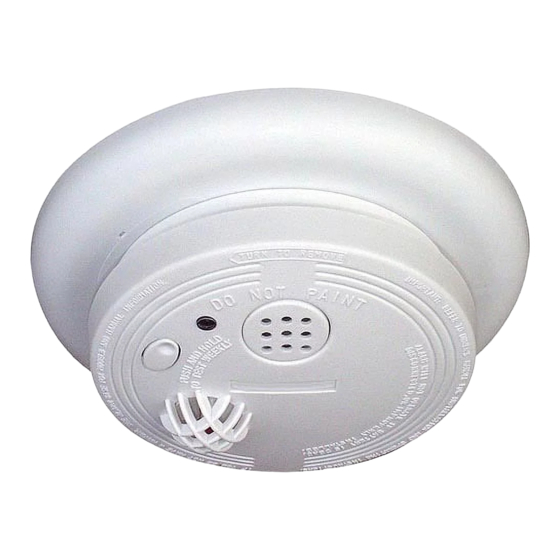
MODEL USI-2430
HEAT ALARM
120 VAC WITH
9V BATTERY BACKUP
USI-2430
120 VAC, 60 Hz, 50 mA maximum, 9 Volt
battery backup
24 units maximum
Up to 5 USI heat alarms or CO alarms and
up to 12 USI smoke alarms and 6 other
non-initiating devices (Relay Modules)
135
o
F (57
o
C) fixed temperature
100
o
F (38
o
C)
-10
o
F to 158
o
2500 square feet (see Note A:)
50 feet
25 feet (see Note B:)
F (-23
o
C to 70
o
C)
Advertisement
Table of Contents

Related Manuals for usi USI-2430


Summary of Contents for usi USI-2430
- Page 1 (CO) or smoke and carbon monoxide / natural gas alarms; 5 other initiating alarms which may be a combination of USI ELECTRIC or UNIVERSAL CO Alarms and Heat Alarms; and six other non- initiating devices such as USI ELECTRIC Relay Modules •...
-
Page 2: Important Safety Information
NOTE A: Maximum alarm coverage has been determined by UL to provide detection time equal to sprinkler devices spaced at 10 foot intervals (100 square foot area) on a smooth ceiling 15 ft. x 8 in. high. Higher ceilings can adversely affect detection time. In some instances, earlier detection may be obtained by reducing the spacing between detectors. - Page 3 EXISTING HOMES NEW CONSTRUCTION HOMES - 3 -...
- Page 4 HEAT ALARM LOCATIONS Install a heat alarm as close to the center of the ceiling as possible. If the center is not practical, mount the heat alarm no closer than 4 inches from a wall or corner. If the ceiling is not practical or the mounting surface becomes considerably warmer or cooler than the room, such as a poorly insulated ceiling, below an unfinished attic or an exterior wall (if local codes allow), install the heat alarm on inside walls with the top of the alarm between 4 and 12 inches from the ceiling/wall intersections.
-
Page 5: Installation
INSTALLATION Installation of this unit must conform to the electrical codes in your area; Article 760 of the National Electrical Code, NFPA 72, 101; SBC (SBCCI); UBC (ICBO); NBC (BOCA): OTFDC (CABO), and any other local or building codes that may apply. Wiring and installation must be performed by a licensed electrician. - Page 6 This alarm may be interconnected with a total of not more than 24 interconnected devices, i.e., as many as 11 other USI ELECTRIC or UNIVERSAL model smoke alarms or combination smoke and carbon monoxide (CO) or smoke and carbon monoxide / natural gas alarms;...
- Page 7 NOTE: Relay Modules/USI-960 will not respond if a CO or Natural Gas alarm / event initiates the alarm. The yellow wire is used only for multiple station operation with USI Models only. Connecting this yellow wire to any other circuits may result in damage.
-
Page 8: Operation, Testing & Maintenance
OPERATION, TESTING & MAINTENANCE OPERATION: The heat alarm is operating once the power is connected and turned on (the battery must also be installed). When air temperature at or above 135 F (57 C) is sensed, the unit sounds a loud alarm which continues until the air temperature drops below 135 This alarm incorporates the internationally recognized horn signal for evacuation. -
Page 9: What To Do When The Alarm Sounds
DEVELOP AND PRACTICE A PLAN OF ESCAPE BASICS OF ESCAPE PLAN o Make a floor plan indicating all doors and windows and at least two escape routes from each room. Second story windows may need a rope or chain ladder. o Have a family meeting and discuss your escape plan, showing everyone what to do in case of fire. - Page 10 If this product is found to be defective, USI’s only obligation, and your exclusive remedy, is the repair or replacement of the product, at USI’s discretion, provided that the product has not been damaged through misuse, abuse, accident, modifications, alteration, neglect or mishandling.
Need help?
Do you have a question about the USI-2430 and is the answer not in the manual?
Questions and answers