Table of Contents
Advertisement
MFJ Super Hi-Q Loop Antenna
MFJ Super Hi-Q Loop Antenna
CAUTION: Do Not Attempt Operation Of This Unit Before Reading All Instructions
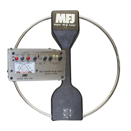
The MFJ "Super Hi-Q Loop" is the best performing and most convenient small space antenna available
to amateurs today. The MFJ-1786 covers 10 MHz to 30 MHz. The MFJ-1788 covers 7 MHz to 21
MHz. The antenna is only 36 inches in diameter and features an indoor semi-automatic tuning unit with
a built-in cross needle wattmeter. All tuning and control voltages are coupled to the antenna through
the coaxial feedline for simple, neat, one wire installation.
The loop antenna element is constructed from thick walled aluminum pipe. Every current carrying
joint is welded to eliminate high resistance pressure contacts that reduce efficiency. The loop element
is tuned with a low-resistance, high current, variable capacitor. The outdoor electrical and mechanical
components are protected by an attractive weather resistant molded cover.
WARNING! Never mount this, or any other antenna near power lines or utility wires! Any
materials: ladders, ropes, or feedlines, that contact power lines can conduct
voltages that kill. Never trust insulation to protect you. Stay away from all power
lines.
THEORY OF OPERATION
When resistive losses in a small loop antenna are kept low, a small loop antenna will transmit nearly as
well as a full size dipole. MFJ was able to make this small loop antenna radiate nearly as well as a full
size dipole by paying special attention to the electrical and mechanical construction of this antenna.
Because radio frequency currents primarily flow near the thin, outer edges of flat conductor loops, flat
conductor loops will have much higher RF losses. To avoid this problem the MFJ "Super Hi-Q Loop"
uses a thick wall, large diameter, round aluminum pipe for the radiating element. This construction
method results in much better performance since the RF losses in the round, large diameter pipe are
many times lower than the losses in a flat conductor.
MFJ forms the large diameter aluminum pipe into a circle on special machines and heli-arc welds all
joints to eliminate resistive pressure connections in the antenna. A specially constructed butterfly
capacitor using arc-welded construction has much lower loss resistance than conventional, less
expensive, pressure contact, air variable capacitors.
The care and expense used in selecting the best materials, not the most convenient materials, has
resulted in an extremely efficient small size antenna. Extensive "on the air" tests have confirmed that
most stations can detect little difference between the signal from the MFJ "Super Hi-Q Loop" and the
signal from a full size dipole at the same height.
1
Instruction Manual
Advertisement
Table of Contents
Troubleshooting

Subscribe to Our Youtube Channel
Related Manuals for MFJ Super Hi-Q Loop


Summary of Contents for MFJ Super Hi-Q Loop
- Page 1 When resistive losses in a small loop antenna are kept low, a small loop antenna will transmit nearly as well as a full size dipole. MFJ was able to make this small loop antenna radiate nearly as well as a full size dipole by paying special attention to the electrical and mechanical construction of this antenna.
-
Page 2: Patterns, Polarization And Location
MFJ Super Hi-Q Loop™ Antenna Instruction Manual PATTERNS, POLARIZATION AND LOCATION This loop antenna can be mounted to provide either vertical or horizontal polarization. To mount this antenna for vertical polarization the loop should be mounted standing up. To mount the loop for horizontal polarization the loop should be mounted so it lays flat. -
Page 3: Nulling Unwanted Signals
MFJ Super Hi-Q Loop Antenna Instruction Manual Signals will be attenuated more than 10 dB if they arrive within 15 degrees of the axis of the loop. In general this antenna, like most others, should be mounted as far away from and as high above other objects as possible. -
Page 4: Horizontal Polarization
MFJ Super Hi-Q Loop™ Antenna Instruction Manual The broadside horizontal radiation that occurs in a small vertical loop is mostly above 10 degree wave angles and extends straight above the loop and to the opposite 10 degree elevation point. True vertical polarization occurs only in line with the loop. - Page 5 Instruction Manual OUTDOOR LOOP INSTALLATION The MFJ "Super HI-Q Loop" has two mounting clamps that are held in place by four 1/4-20 7/16" hex head bolts. The mounting clamps accept masts up to 1-1/2" outside diameter. Before mounting the antenna read the section on "PATTERNS, POLARIZATION AND LOCATION".
- Page 6 MFJ Super Hi-Q Loop™ Antenna Instruction Manual The mast should be grounded for lightning protection and electrical safety. The coax feedline should be dressed down the mast and have it's shield grounded at the point where it enters a building for lightning protection.
-
Page 7: Indoor Control Box Installation
The control unit of the MFJ "Super Hi-Q Loop" can be located at any position that allows easy access to the controls of the unit and the transceiver. The coax lines should be good quality 50 ohm lines and should be kept reasonably short to reduce losses. -
Page 8: Control Head Theory And Operation
40 seconds of fast tuning. CONTROL HEAD POWER The MFJ "Super Hi-Q Loop" control head requires a 9-15 VDC, ungrounded power supply. The power jack accepts a 2.1mm coaxial plug with the center conductor positive. The MFJ-1312B is supplied for 110 Vac operation. -
Page 9: Testing And Operation
MFJ Super Hi-Q Loop Antenna Instruction Manual The control head draws 6 mA on standby. The current increases to 20 mA while tuning (because of the tuning motor in the loop and the LED's). Additionally, the meter lamp can draw 35 mA of current. - Page 10 MFJ Super Hi-Q Loop™ Antenna Instruction Manual ON THE CONTROL HEAD CAN DAMAGE THE CONTROL HEAD OR OTHER EQUIPMENT! See figure 6. Be sure the cable to the transceiver and the power supply (if used) are connected. Plug the power supply into an 110Vac outlet.
-
Page 11: General Operation And Troubleshooting
OF THE LOOP IS VERY SHARP! It takes a little practice to catch the lowest SWR. Stop transmitting and ID when done tuning! Congratulations! You have successfully tested and operated your MFJ "Super Hi-Q Loop" installation. You should now be familiar enough with the controls and how the controls respond to go to the easier and more general operating instructions. -
Page 12: Tuning With A Known Direction Of Frequency Movement
MFJ Super Hi-Q Loop™ Antenna Instruction Manual Press the AUTO BAND SELECT "DOWN" button. The yellow FREQ "DOWN" LED should light. The control box should beep and the yellow FREQ "DOWN" LED should go out after the operating frequency range is found. Release the Auto Band Select "DOWN" button and a red or green MOVE "UP"... -
Page 13: Tuning The Antenna For Use With A Receiver
MFJ Super Hi-Q Loop Antenna Instruction Manual TUNING THE ANTENNA FOR USE WITH A RECEIVER This method of tuning should be used when the operator is trying to use the antenna with a reciever. Tuning a receiving antenna is usually accomplished by setting the receiver on the desired frequency, and then tuning the antenna while listening to audio of either the wanted station itself or the existing white noise level in the spectrum if no station exists. -
Page 14: Technical Assistance
You can also send questions by mail to MFJ Enterprises, Inc., 300 Industrial Park Road, Starkville, MS 39759; by FAX to 601-323-6551; or by email to mfj@mfjenterprises.com.
Need help?
Do you have a question about the Super Hi-Q Loop and is the answer not in the manual?
Questions and answers