Table of Contents
Advertisement
FEATURES..................................................................................................................... 1
SPECIFICATIONS ......................................................................................................... 1
FRONT PANEL INDICATORS AND CONTROLS ......................................... 1
CONTROLS........................................................................................................ 1
REAR PANEL CONNECTORS......................................................................... 1
OTHER................................................................................................................ 2
CONTOLS / CONNECTORS......................................................................................... 2
FRONT PANEL FUNCTIONS........................................................................... 2
REAR PANEL CONNECTORS......................................................................... 4
INSTALLATION ............................................................................................................ 5
INSTALLATION PROCEDURES ..................................................................... 5
BEFORE OPERATION ...................................................................................... 5
TUNING.......................................................................................................................... 6
USING THE BARGRAPH ............................................................................................. 7
NOTES ............................................................................................................................ 8
TECHNICAL ASSISTANCE ......................................................................................... 8
METER CALIBRATION ............................................................................................... 9
METER CALIBRATION PEOCEDURE........................................................... 9
YOUR NOTES................................................................................................................ 10
SCHEMATIC DIAGRAM.............................................................................................. 11
Table of Contents
Advertisement
Table of Contents

Related Manuals for Vectronics HFT-1500


Summary of Contents for Vectronics HFT-1500
-
Page 1: Table Of Contents
Table of Contents FEATURES........................1 SPECIFICATIONS ......................1 FRONT PANEL INDICATORS AND CONTROLS ......... 1 CONTROLS......................1 REAR PANEL CONNECTORS................. 1 OTHER........................ 2 CONTOLS / CONNECTORS..................2 FRONT PANEL FUNCTIONS................2 REAR PANEL CONNECTORS................. 4 INSTALLATION ......................5 INSTALLATION PROCEDURES ..............5 BEFORE OPERATION .................. -
Page 3: Features
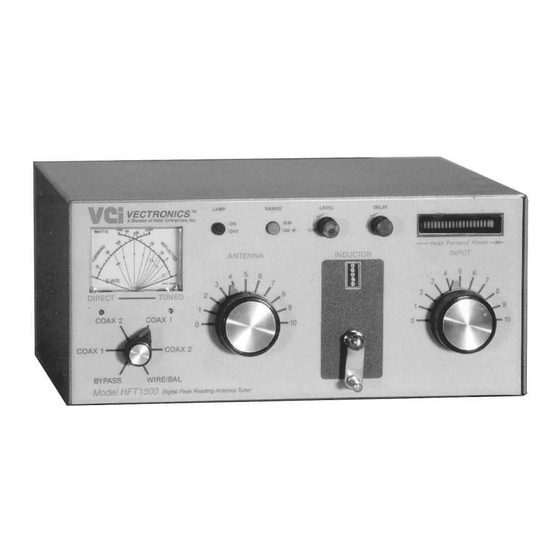
VECTRONICS HFT-1500 Digital Bargraph Antenna Tuner FEATURES The Vectronics HFT-1500 optimizes the performance of your antenna and transmitter or SWL receiver by providing adjustable impedance matching. The HFT-1500 also measures the Power and Standing Wave Ratio (SWR), which allows you to tune the indicted SWR to the lowest possible ratio for the selected transmit frequency. -
Page 4: Other
HFT-1500 Digital Antenna Tuner with Roller Inductor Owner's Manual Bypass ........SO-239 connector RF Input......... SO-239 connector Balanced Line......Dual high voltage Derlin terminal post; includes 4:1 2.5 kW voltage balun (Ruthroff type). End-Fed Wire ......High voltage Derlin terminal post. - Page 5 HFT-1500 Digital Antenna Tuner with Roller Inductor Owner's Manual The SWR in measured where the two needles intersect on the red scale. 3. ANTENNA Continuously adjustable output capacitor. 4. DIRECT-TUNED MODE SWITCH Six-position rotary switch an output coaxial connector. 1. DIRECT BYPASS selects BYPASS COAX connector bypassing the impedance matching circuit but providing SWR, FORWARD, and REFLECTED power meter readings.
-
Page 6: Rear Panel Connectors
HFT-1500 Digital Antenna Tuner with Roller Inductor Owner's Manual REAR PANEL CONNECTORS 1. RF INPUT Coaxial connector for input from SWL receiver or transmitter. 2. COAX 1 Coaxial connector for output to Antenna One. 3. COAX 2 Coaxial connector for output to Antenna Two. -
Page 7: Installation
We recommend keeping the packing carton for moving, storage, or reshipping the tuner. Select a location for the HFT-1500 that allows the connectors to be free of any possible contact during operation. WARNING: SOME BALANCED OR END-FED ANTENNAS WILL PRODUCE HIGH RF VOLTAGES AT THE BANANA CONNECTORS. -
Page 8: Tuning
HFT-1500 Digital Antenna Tuner with Roller Inductor Owner's Manual TUNING 1. Select the band and frequency of desired operation. 2. Set TRANSMITTER, ANTENNA, and INDUCTOR controls to the suggested settings before applying transmitter power. Actual settings may vary from antenna to antenna. -
Page 9: Using The Bargraph
HFT-1500 Digital Antenna Tuner with Roller Inductor Owner's Manual controls for a minimum REFLECTED reading while maintaining a FORWARD reading of 50-100 watts using your transmitter power control. 9. Read the SWR on the red scale at the point where the two needles intersect. Repeat step 8 until the lowest SWR reading is obtained. -
Page 10: Notes
If the manual does not reference your problem or your problem is not solved by reading the manual you may call VECTRONICS at 601-323-5800. You will be best helped if you have your unit, manual and all information on your station handy so you can answer any questions the technicians may ask. -
Page 11: Meter Calibration
Owner's Manual METER CALIBRATION METER CALIBRATION PEOCEDURE • • • • Connect the HFT-1500 as depicted in Figure 9.1. • • • • Connect external 50Ω load to COAX 1 connector and the HF amplifier to the RF INPUT connector. -
Page 12: Your Notes
HFT-1500 Digital Antenna Tuner with Roller Inductor Owner's Manual • • • • Reverse the connections on RF INPUT and COAX 1. • • • • Select the 300 watt range on the RANGE button, apply 100 Watts of RF power at 7.0 MHz and adjust R2 for a forward reading on 100 Watts. -
Page 13: Schematic Diagram
HFT-1500 Digital Antenna Tuner with Roller Inductor Owner's Manual SCHEMATIC DIAGRAM...
Need help?
Do you have a question about the HFT-1500 and is the answer not in the manual?
Questions and answers