Advertisement
VC-300DLP Antenna Tuner
Owner's Manual
VECTRONICS
VC-300DLP Antenna Tuner
FEATURES
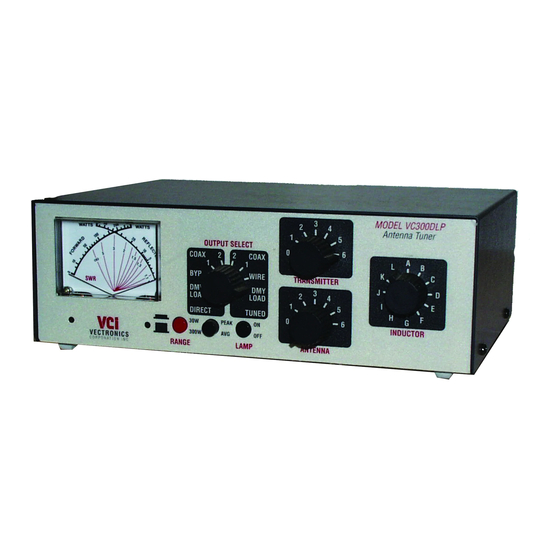
The Vectronics VC-300DLP Antenna Tuner optimizes the performance of your antenna and
transmitter, receiver, or transceiver by providing adjustable impedance matching. The VC-
300DLP also measures the Power and Standing Wave Ratio (SWR), allowing you to adjust for
the lowest possible ratio for the selected transmit frequency. The VC-300DLP utilizes a
precision frequency compensated lighted dual movement SWR / power meter which can show
either peak or average readings. Also included is a built-in Dummy Load for tuning purposes
which is easily switched in and out of the circuit.
SPECIFICATIONS
FRONT PANEL INDICATORS
Meter ..................................... Dual movement lighted cross needle Power and SWR meter.
FRONT PANEL CONTROLS
TRANSMITTER ................... Continuous rotation capacitor.
ANTENNA............................ Continuous rotation capacitor.
INDUCTANCE ..................... 48 Turn Switched Rotary Inductor.
OUTPUT SELECT ............... Eight position: DIRECT Coax 1, Coax 2, Bypass, and Dummy
Load; TUNED Coax 1, Coax 2, Wire, and Dummy Load.
RANGE ................................ 2 position switch: 30W / 300W
METER ................................. 2 position switch: PEAK/AVG
LAMP.................................... 2 position switch: ON / OFF
REAR PANEL CONNECTORS
COAX 1................................. SO-239 Connector
COAX 2................................. SO-239 Connector
BYPASS................................ SO-239 Connector
TRANSMITTER IN.............. SO-239 Connector
BALANCED LINE ............... Dual Banana Jack
WIRE..................................... Banana Jack
1
Advertisement
Table of Contents

Subscribe to Our Youtube Channel
Related Manuals for Vectronics VC-300DLP


Summary of Contents for Vectronics VC-300DLP
-
Page 1: Specifications
300DLP also measures the Power and Standing Wave Ratio (SWR), allowing you to adjust for the lowest possible ratio for the selected transmit frequency. The VC-300DLP utilizes a precision frequency compensated lighted dual movement SWR / power meter which can show either peak or average readings. -
Page 2: Controls & Connectors
VC-300DLP Antenna Tuner Owner's Manual OTHER Frequency Coverage....1.8 - 30 MHz Power........150 watts Continuous; 300 watts pep, SSB Dimensions......3.5" (89mm) H x 10.2" (266mm) W x 9.4" (240mm) D. Weight ........3.6 lbs. (1.6 kg.) CONTROLS / CONNECTORS FRONT PANEL FUNCTIONS 1. - Page 3 VC-300DLP Antenna Tuner Owner's Manual COAX 2 selects the COAX 2 Connector, bypassing the impedance matching circuit but providing normal meter readings. TUNED MODE COAX 1 selects the COAX 1 connector through the impedance matching circuit. COAX 2 selects the COAX 2 connector through the impedance matching circuit.
-
Page 4: Installation
If any damage is apparent, notify the transportation carrier or dealer immediately. recommend keeping the packing carton for moving, storage, or reshipping the tuner. Select a location for the VC-300DLP that allows the connectors to be free of any possible contact during operation. - Page 5 OUTPUT SELECTOR switch. 6. To avoid possible damage to the VC-300DLP, set the TRANSMITTER, ANTENNA, and RANGE switches as outlined in the next section before applying transmitter power.
- Page 6 VC-300DLP Antenna Tuner Owner's Manual 5. Set OUTPUT SELECTOR switch to the proper selection on the TUNED side of the switch. Selecting any of the DIRECT positions by passes the tuning circuitry altogether. 6. Rotate the TRANSMITTER, ANTENNA, and INDUCTOR controls for maximum noise or signal as heard on your receiver.
-
Page 7: Technical Assistance
VECTRONICS at 601-323-5800. You will be best helped if you have your unit, manual and all information on your station handy so you can answer any questions the technicians may ask. -
Page 8: Meter Calibration Procedure
VC-300DLP Antenna Tuner Owner's Manual METER CALIBRATION METER CALIBRATION PROCEDURE Connect transceiver to TRANSMITTER IN connector. Connect external 50 load to COAX 2 connector. Set the OUTPUT SELECT switch to the COAX 2 DIRECT position. Set the RANGE button to 300 W and the PEAK/AVG button to AVG. -
Page 9: Schematic Diagram
VC-300DLP Antenna Tuner Owner's Manual SCHEMATIC DIAGRAM VC-300DLP...
Need help?
Do you have a question about the VC-300DLP and is the answer not in the manual?
Questions and answers