Table of Contents
Advertisement
Advertisement
Table of Contents

Related Manuals for Kantech ioProx P700WLS

Summary of Contents for Kantech ioProx P700WLS
- Page 1 P700WLS IoProx Receiver Installation Manual DN1628-0609...
- Page 2 The entire manual should be carefully read. Kantech Systems Tel.: 1 (450) 444-2030 Toll Free (US & Canada): 1 888 222-1560 Fax: 1 (450) 444-2029 Web Site: www.kantech.com 2006 Tyco Safety Products, Canada, Ltd. All rights reserved. Specifications may be modified without notice. DN1628-0609...
-
Page 3: Table Of Contents
P700WLS IoProx Receiver Installation Manual Table of Contents System Overview .......................1 Inventory ........................... 1 Technical Specifications ...................2 Installing the P700WLS IoProx Receiver ..............3 Global Coverage ........................3 Power Supply and Grounding....................3 Recommended Wiring Distance at 12 Vdc................3 Data Path Selector Settings ..................... 4 Receiver Terminal Block Location................... -
Page 4: System Overview
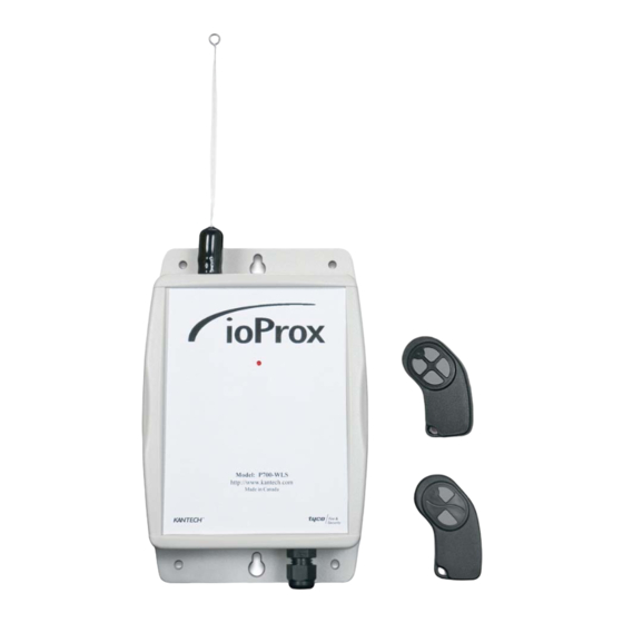
The P700WLS IoProx receiver unit is designed to interface with an access control panel card reader port using the Wiegand protocol or the Kantech eXtended Secure Format (XSF). The Ioprox receiver can read from a distance of up to 45.72 m. (150 ft.) with a power dipole antenna or 30.48 m. (100 ft.) with a standard antenna. -
Page 5: Technical Specifications
P700WLS IoProx Receiver Installation Manual Technical Specifications P700WLS IoProx Receiver P72WLS/P74WLS Transmitters CR2032 3V lithium battery, included (3 year average 12-24 VDC lifetime) Power: Power: 50mA (stand-by) 100mA Current: (peak) Operating temperature: 0°C to 70°C (32°F to 158°F) XSF or 26-bit Wiegand Output: selectable Dimensions (HWD) cm:... -
Page 6: Installing The P700Wls Ioprox Receiver
P700WLS IoProx Receiver Installation Manual Installing the P700WLS IoProx Receiver Global Coverage When global coverage of a large area is required, there should be a sufficient number of receivers to give overlapping coverage of receiving patterns. Use the SW terminals if the receiver antennas are less than 30.5 m (100 ft) apart. -
Page 7: Data Path Selector Settings
P700WLS IoProx Receiver Installation Manual Data Path Selector Settings The receiver unit provides for field selectable pins JP2 located near the center of the board (Figure 1) Receiver Terminal Block Location The receiver terminal block is removable. (Refer Figure 1) It can be mounted vertically or horizontally. Connect 22 to 14 AWG wires to the blue terminal block. -
Page 8: S1 Receiver Configuration
Placing the DIP switches in the ON or OFF position determines which specific button on the multi-button transmitter will activate the receiver and Wiegand format to be transmitted to the control panel. (See Table 1 below) Data Path Selector Settings: Kantech XSF (default): Position 4 (ON). 26-bit Wiegand: Position 4 (OFF). Button 1 Button 3 The selectors for position 1 and 2 select which of the four buttons will activate the receiver. -
Page 9: Receiver Wiring Diagrams
P700WLS IoProx Receiver Installation Manual Receiver Wiring Diagrams Figure 2 Typical Installation and Two Receivers Connected to One Port Installations DN1628-0609... -
Page 10: Testing The Receivers
P700WLS IoProx Receiver Installation Manual Testing the Receivers PCB LED Indicators All LEDs are located on the PC board, inside the box. LED Location Figure 3 LEDs Location Flashes if the transmitter encryption code does not match the receiver configuration, and will not operate the receiver. -
Page 11: Receiver Relay
P700WLS IoProx Receiver Installation Manual Receiver Relay The receiver relay activates for one second when a valid button on the transmitter triggers the receiver. The relay on the receiver can be used for testing purposes by adding an audible or visual device to confirm the receiver is receiving the signal consistently from the desired location of the transmitters. -
Page 12: Testing The Transmitters
P700WLS IoProx Receiver Installation Manual Testing the Transmitters Operating Instructions The following instructions can be used for both models (2 or 4 buttons) 1. On the key tag transmitter, press for one (1) second the button you programmed earlier to activate the receiver.
Need help?
Do you have a question about the ioProx P700WLS and is the answer not in the manual?
Questions and answers