Monessen Hearth LO-RIDER LSTF36 Installation And Operating Instructions Manual
Designer vent-free fireboxes
Hide thumbs
Also See for LO-RIDER LSTF36:
- Installation and operating instructions manual (20 pages) ,
- Product specifications (1 page) ,
- Brochure & specs (6 pages)
Table of Contents
Advertisement
Quick Links
LO-RIDER
DESIGNER VENT-
FREE FIREBOXES
INSTALLATION AND OPERATING
INSTRUCTIONS
MODELS: LSTF36, LPF36, LRCF36, LLCF36
For use only with a listed gas-fi red
unvented decorative room heater
not to exceed 40,000 BTU/hr. DO
NOT BUILD A WOOD FIRE.
Carefully review the instructions
supplied with the decorative
type unvented room heater
for the minimum fi replace size
requirement.
DO NOT INSTALL AN APPLIANCE
IN THIS FIREBOX UNLESS THIS
FIREBOX MEETS THE MINIMUM
DIMENSIONS REQUIRED FOR
THE INSTALLATION.
If the information in this manual is not followed exactly, a fi re
or explosion may result causing property damage, personal
injury or loss of life.
– Do not store or use gasoline or other fl ammable vapors and
liquids in the vicinity of this or any other appliance.
– WHAT TO DO IF YOU SMELL GAS
• Do not try to light any appliance.
• Do not touch any electrical switch; do not use any phone
in your building.
• Immediately call your gas supplier from a neighbor's phone.
Follow the gas supplier's instructions.
• If you cannot reach your gas supplier, call the
fi re department.
– Installation and service must be performed by a qualifi ed
installer, service agency or the gas supplier.
WARNING: Improper installation, adjustment, alteration, service
or maintenance can cause injury or property damage. Refer to
this manual. For assistance or additional information consult
a qualifi ed installer, service agency, or the gas supplier.
READ AND SAVE THESE INSTRUCTIONS
WARNINGS
Advertisement
Table of Contents

Subscribe to Our Youtube Channel
Related Manuals for Monessen Hearth LO-RIDER LSTF36


Summary of Contents for Monessen Hearth LO-RIDER LSTF36
- Page 1 DESIGNER VENT- FREE FIREBOXES INSTALLATION AND OPERATING INSTRUCTIONS MODELS: LSTF36, LPF36, LRCF36, LLCF36 WARNINGS If the information in this manual is not followed exactly, a fi re or explosion may result causing property damage, personal injury or loss of life.
-
Page 2: Table Of Contents
CONTENTS IMPORTANT SAFETY INFORMATION ....................3 PLANNING the INSTALLATION ......................4 LOCATION of FIREBOX ........................5 CLEARANCES and HEIGHT REQUIREMENTS ................... 7 FIREPLACE FRAMING ........................9 FIREPLACE INSTALLATION ......................11 GAS LINE INSTALLATION ........................14 CANOPY INSTALLATION ........................15 WIRING to JUNCTION BOX ....................... 16 GLASS CLEANING ........................... -
Page 3: Important Safety Information
IMPORTANT SAFETY INFORMATION INSTALLER OWNER Please leave this manual with the appliance. Please retain this manual for future reference. IMPORTANT Read these instructions carefully before installing this vent-free fi rebox. • Improper installation or use of the fi rebox can cause serious injury or death from fi... -
Page 4: General Installation Information
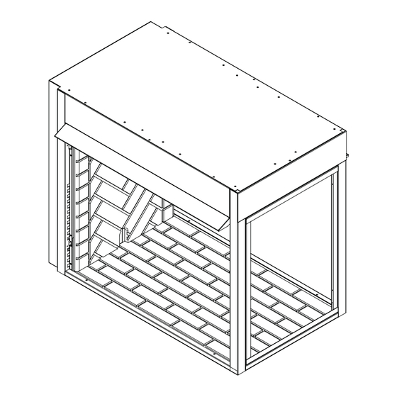
FIREBOX IF THE MINIMUM CLEARANCE AND HEIGHT REQUIREMENTS OF THE LOG SET ARE TOO LARGE FOR THE FIREBOX. The LSTF36, LPF36, LRCF36, and LLCF36 Series are vent-free fireboxes. They feature a self-contained heat-circulating system. These units also feature a 2-in-1 flexible-face system (except for corner unit) that converts the circulating system into a radiant system in seconds. -
Page 5: Planning The Installation
PLANNING THE INSTALLATION In planning the installation for the appliance it is necessary to determine where the unit is to be installed and whether optional accessories are desired. Gas supply piping should also be planned. The following steps represent the normal sequence of installation. -
Page 6: Location Of Firebox
LOCATION OF FIREBOX Carefully select the best location for installation of your vent-free firebox. The following factors should be taken into con- sideration. • Clearance to side wall, ceiling, woodwork, and windows. Refer to “CLEARANCES and HEIGHT REQUIREMENTS” section below and on pages 8 and 9. Minimum clearances to combustibles must be maintained. •... -
Page 7: Clearances And Height Requirements
3. Back Wall Clearance — The appliance may be placed against a combustible back wall. 4. Parallel Wall Clearance — The clearance from the opening of the firebox to any wall that is parallel to the opening should not be less than 36" (LSTF36 and LPF36 models only). Refer to Figure 4. 42"... - Page 8 CLEARANCES and HEIGHT REQUIREMENTS Mantel clearances — The canopy supplied with 12" the unit must be installed. If a combustible mantel 10" 8" is installed, it must meet the clearance requirements 6" detailed in Figure 6. 24" 12" 2.5" 22" Floor clearance —...
-
Page 9: Fireplace Framing
FIREPLACE FRAMING Firebox framing can be built before or after the appliance is set in place. Construct firebox framing following Figures 9 through 14 on pages 9 and 10 for your specific installation requirements. Refer to Figure 1 on Page 5 for firebox dimensions. The framing headers may rest on the top of the firebox standoffs. - Page 10 22 3/16" Figure 13 - Top View of Framing Specifi cations for Figure 14 - Framing Specifi cations for See-Through Unit (Model LSTF36) See-Through Unit (Model LSTF36) The fi replace must be installed giving full consideration to the clearance and height requirements identifi...
-
Page 11: Fireplace Installation
FIREPLACE INSTALLATION PENINSULA UNIT (LPF36) INSTALLATION 1. Attach nailing flanges in desired position. See Figure 2. Slide firebox into prepared framing or position firebox in its final position and frame later. 3. Level and plumb firebox by checking edges of firebox. Shim if necessary. - Page 12 FIREPLACE INSTALLATION SEE-THROUGH UNIT (LSTF36) INSTALLATION 1. Attach nailing flanges in desired position. See Figure 16. 3. Slide firebox into prepared framing or position firebox in its final position and frame later. 4. Level and plumb firebox by checking edges of firebox. Shim if necessary.
- Page 13 FIREPLACE INSTALLATION RIGHT (LRCF36) AND LEFT (LLCF36) CORNER INSTALLATION 1. Attach nailing fl anges in desired position. See Figure 16. 2. Slide firebox into prepared framing or position firebox in its final position and frame later. 3. Level and plumb firebox by checking edges of firebox. Shim if necessary. 4.
-
Page 14: Gas Line Installation
GAS LINE INSTALLATION Plumbing connections should only be performed by a qualifi ed, licensed plumber. Main gas supply must be off when plumbing gas line to fi replace or performing service. Consult all local codes. All gas piping must be installed to comply with local codes, or in the absence of local codes, with the latest edition of the National Fuel Gas Code, ANSI Z223.1/NFPA54. -
Page 15: Canopy Installation
2. Secure canopy with five (5) screws provided. modifi ed or replaced with a canopy 3 Repeat on other side for See-Through Unit (LSTF36) and that may be provided with the Peninsula Unit (LPF36). Install the 20" canopy on the unvented decorative room heater. -
Page 16: Wiring To Junction Box
WIRING TO JUNCTION BOX & GLASS CLEANING FORCED AIR KIT If you are installing the forced air kit Model BLOTDL on the LSTF36, LPF36, GCRF36 or GCLF36 units, see the installa- tion instructions below supplied with kit. Electrical connections should only be performed by a qualifi ed, licensed electrician, main power must be off when connecting to main electrical power supply or performing service. -
Page 17: Illustrated Parts List
ILLUSTRATED PARTS LIST Figure 21 - Exploded View STANDARD FEATURES ITEM DESCRIPTION LRCF/LLCF 36” Canopy 71D0500 71D0500 71D0500 20” Canopy 79D0082(1) Screen Panel 79D0001(4) 79D0001(4) 79D0001(3) Screen Rod Side 26D0138(4) 26D0138(4) 26D0138(2) Screen Rod End 43D0116(1) Brick Panel Common 79D0093(1) 79D0093(1) 79D0093(1) Brick Panel Corner... -
Page 18: Using Optional Outside Air Kit
USE OF OPTIONAL AK-4 OUTSIDE AIR KIT COMBUSTION AIR 1. Locate combustion air assembly at an exterior location which is not likely to be accidentally blocked in any manner. Locate assembly amin. of 12" above the snow line to prevent blockage by snow accumulation. 2. - Page 19 USE OF OPTIONAL AK-4 OUTSIDE AIR KIT The use of outside air for combustion is optional unless required by building codes. It is only necessary to supply outside combustion air to one side of the fi replace. Use the model AK4 combustion air kit. MODEL AK-4 COMBUSTION AIR ASSEMBLY DO NOT remove the 1.
- Page 20 USE OF OPTIONAL AK-4 OUTSIDE AIR KIT MODEL AK-4 COMBUSTION AIR ASSEMBLY (CONTINUED) Approximately 7. If the duct is the insulated type, push the insulation back from one end of 2" the duct approximately 2". See Figure 29. Duct Connector 8.
- Page 21 NOTES 79D0004...
- Page 22 NOTES 79D0004...
- Page 23 NOTES 79D0004...
-
Page 24: Warranty
Ceramic Fiber Logs, Catalytic Filter and Aluminized Burners. BASIC WARRANTY Monessen Hearth Systems (MHS) warrants the components and materials in your gas appliance to be free from manufacturing and material defects for a period of two years from date of installation. After installation, if any of the components manufactured by MHS in the appliance are found to be defective in materials or workmanship, MHS will, at its option, replace or repair the defective components at no charge to the original owner.
Need help?
Do you have a question about the LO-RIDER LSTF36 and is the answer not in the manual?
Questions and answers