Advertisement
Available languages
Available languages
Advertisement
Table of Contents

Summary of Contents for Prime R125-2
- Page 1 110711BCF 1230-57382-04 Printed in China...
-
Page 2: Table Of Contents
©2011 Rockford Corporation. All Rights Reversed. ROCKFORD FOSGATE and associated logos where applicable are registered trademarks of Rockford Corporation in the United States and/or other countries. All other trademarks are the property of their respective owners. Specifications subject to change without notice. -
Page 3: Specifications
Dimensions (LxWxH) 7.7” x 7.7” x 2.4” (19.6cm x 19.6cm x 6.1cm) CEA 2006 Power ratings on Rockford Fosgate amplifiers conform to CEA-2006 industry standards. These guidelines mean your amplifier’s output power ratings are REAL POWER numbers, not inflated marketing ratings. -
Page 4: Design Features
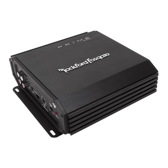
Design Features Gain Control The input gain control is preset to match the output of most source units. Power LED Power LED illuminates blue when the unit is turned on. RCA Input/Pass-Thru Jacks The industry standard RCA jacks provide an easy connection for signal level input. - Page 5 Design Features Crossover Switch Selectable switch for 80Hz High-Pass (HP),All Pass (AP), or Low-Pass (LP) operation. Variable Crossover Is a built-in 12dB/octave Butterworth filter with a crossover point variable from 50Hz to 250Hz. Protect LED Protect LED illuminates red if a short circuit or to low of an impedance is detected at the speaker connections.
-
Page 6: Installation
Contents working on any vehicle. 7. Never run wires underneath the vehicle. Running the wires inside the • R125-2 - Prime 2 Channel Amplifier vehicle provides the best protection. • Mounting Hardware 8. Avoid running wires over or through sharp edges. Use rubber or plastic grommets to protect any wires routed through metal, especially •... - Page 7 Installation Before installation, disconnect the battery neg- 7. Securely mount the amplifier to the vehicle or amp rack. Be careful not ative (-) terminal to prevent damage to the unit, to mount the amplifier on cardboard or plastic panels. Doing so may fire and/or possible injury.
- Page 8 Installation Stereo Wiring illus.-2.1...
- Page 9 Installation Bridged Wiring illus.-2.2...
-
Page 10: Operation
Operation Adjusting Gain Punch Bass This works along with the crossover switch on the amplifier. When set to 1. Turn amplifier gains to minimum (counter-clockwise). Low-Pass (LP) operation, this is a variable Bass Boost. Set this to your personal preference while listening to the system. 2. -
Page 11: Troubleshooting
Troubleshooting Troubleshooting Step 5. Check Amplifier if you experience excess Engine Noise. NOTE: If you are having problems after installation follow the Trouble- 1. Route all signal carrying wires (RCA, Speaker cables) away from shooting procedures below. power and ground wires. Step 1. - Page 12 MISE EN GARDE: si vous ne vous sentez pas à l’aise pour effectuer vous-même le câblage de Voici la liste d’outils requis pour l’installation : votre nouvel appareil, veuillez confier l’installation à votre distributeur agréé Rockford Fosgate. • Porte-fusible et fusible. (Voir les •...
- Page 13 Françias Préparez le fil de masse NOIR à connecter à l’amplificateur en dénudant son extrémité Dépannage sur 1 cm (3/8 po). Sertissez le fil dénudé dans un connecteur en fourche ou en anneau et REMARQUE: si vous éprouvez des difficultés après l’installation,appliquez les procédures de branchez-le sur la borne de masse (GND).
- Page 14 PRECAUCIÓN: Si no se siente capaz de instalar el cableado de su nueva unidad, por favor La siguiente es una lista de las herramientas necesarias para la instalación: consulte a su DistribuidorAutorizado Rockford Fosgate local sobre la instalación. • Portafusibles y fusible (Consulte •...
- Page 15 Español terminal de anillo del tamaño correcto al cable.Use el terminal de anillo para conectar al Solución De Problemas borne positivo de la batería. NOTA: Si tiene problemas después de la instalación,siga los procedimientos de solución de Prepare el cable NEGRO (cable de tierra) para fijarlo al amplificador pelando 3/8 pulg. de problemas descritos a continuación.
- Page 16 VORSICHT: Wenn Sie beim Einbau des Geräts unsicher sind, lassen Sie es bitte von einem (Siehe Technische Daten für Durchmesser) qualifizierten Rockford Fosgate Techniker einbauen. Bemessungsstrom) • Verschiedene Anschlussteile VORSICHT: Entfernen Sie vor dem Einbau den negative Batteriepol, um Schäden am Gerät, •...
- Page 17 Deutsch 13 mm vom Batterieende des Stromkabels abisolieren und einen Ringadapter von Fehlerbeseitigung geeigneter Größe an das Kabel crimpen.Den Ringadapter zumAnschließen an den HINWEIS: Falls Sie nach demEinbau Probleme haben, befolgen Sie die nachfolgendenVer- positivenAnschluss der Batterie benutzen. fahren zur Fehlerbeseitigung: Das SCHWARZE Kabel (Erdungskabel) durch Abisolieren von 9,5 mm am Ende des Step 1.
- Page 18 ATTENZIONE: Se aveste dei dubbi circa l’installazione, rivolgetevi ad un tecnico qualificato informazioni sulla portata dei fusibili, diametro di 0,32 cm della Rockford Fosgate. consultare le specifiche.) • Connettori vari ATTENZIONE: Prima dell’installazione, scollegate il terminale negativo (-) della batteria per •...
- Page 19 Italiano cavo un terminale ad anello di dimensione opportuna. Servirsi del terminale ad anello Individuazione/Riparazione Guasti per collegare il cavo al positivo della batteria. NOTA: Se incontraste dei problemi dopo l’installazione, seguite le procedure per la localiz- Preparate il filo NERO (cavo della messa a terra) per poterlo attaccare all’amplificatore, zazione e la riparazione dei guasti elencate di sotto.
- Page 20 What is Covered This warranty applies only to Rockford Fosgate products sold to consumers by Authorized Rockford Fosgate Dealers in the United States of America or its possessions. Product purchased by consumers from an Authorized Rockford Fosgate Dealer in another country are covered only by that country’s Distribu- tor and not by Rockford Corporation.

Need help?
Do you have a question about the R125-2 and is the answer not in the manual?
Questions and answers