Table of Contents
Advertisement
INCLUDES VERSIONS:
TI-14 V.02
TI-14 V.03
TI-14 V.04
TI-14 V.05
INVICTA USA
(877) 308-6423 – East
(800) 499-4682 - West
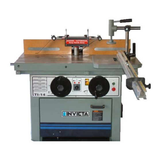
SHAPER
by
INVICTA
NON-TILTING
TILTING SPINDLE
SLIDING TABLE
TILTING SPINDLE / SLIDING TABLE
OPERATORS MANUAL
TI-14
English Version
Revision Nº 01
Model
Advertisement
Table of Contents

Related Manuals for Invicta TI-14


Summary of Contents for Invicta TI-14
- Page 1 OPERATORS MANUAL SHAPER Model TI-14 INVICTA INCLUDES VERSIONS: NON-TILTING TI-14 V.02 TILTING SPINDLE TI-14 V.03 SLIDING TABLE TI-14 V.04 TILTING SPINDLE / SLIDING TABLE TI-14 V.05 INVICTA USA English Version (877) 308-6423 – East Revision Nº 01 (800) 499-4682 - West...
-
Page 2: Safety Rules
2. If you are not thoroughly familiar and comfortable with the adjustment and operation of the machine, ask for instruction from your supervisor or a fully qualified person. You may also contact Invicta USA. 3. Before the initial operation of the machine, remove all packaging, shipping grease and fully assemble the machine. - Page 3 See the electrical diagrams for three-phase on page 08. If further information is needed or contact Invicta USA. Loading and unloading When loading and unloading the machine there should be no pressure on areas which could affect its functioning.
- Page 4 SHAPER Technical Specification Version Table dimensions (in) 35.43 x 43.3 35.43 x 43.3 35.43 x 43.3 35.43 x 43.3 Working height (in) 33.46 33.46 33.46 33.46 Spindle vertical travel (in) 5.51 5.51 5.51 5.51 Morse taper Spindle diameter (in) .75 & 1.25 .75 &...
- Page 5 SHAPER Changing the Spindle INVICTA TECHNICAL BULLETIN Subject: Correct Procedure for Changing Spindles Pre-installation Instructions Remove all cosmoline from interchangeable spindle and mating main spindle before mounting tooling. It is very important that the locking nut, threads and taper be clean.
- Page 6 SHAPER Mod. TI-14 Accessories 1 Special wrench 1 Open end wrench 38 mm 1 Open end wrench 10 x 13 mm 1 Open end wrench 19 x 24 mm 1 Open end wrench 24 x 27 mm 1 Allen wrench 5 mm 1 Cutter Shaft(Spindle) Ø3/4”...
- Page 7 SHAPER Mod. TI-14 Adjustment Instructions Controls 1 – On (Green) and Off (Red) Switches 6 – Spindle lock lever 2 - Vertical Height Adjusting Handwheel 7 - Tilt Adjustment Handwheel (Ver. 3 and 5) 3 – Handwheel Lock 8 – Brake 4 –...
-
Page 8: Table Inserts
SHAPER Mod. TI-14 Change Speeds and Adjustment of Belt Tension To change the spindle speed, pull lever nº 5 (fig.3 pg.6) and loosen the belt. Change the belt position both pulleys, and tighten the belt by returning the lever to its original position. Adjust belt tension as belt wears by nuts “G”... -
Page 9: Electrical Diagram
SHAPER Mod. TI-14 ELECTRICAL DIAGRAM IMPORTANT SELECT THE VOLTAGE (230/460V) OF YOUR INTERNAL ELECTRIC NETWORK. THE VOLTAGE SELECTION KEY IS LOCATED ON THE ELECTRICAL BOX. FOR YOU SAFETY THE VOLTAGE SELECTION KEY IS ON NEUTRAL POSITION. -
Page 10: Electrical Box
SHAPER Mod. TI-14 ELECTRICAL BOX... -
Page 11: Replacement Parts
SHAPER Mod. TI-14 Version 02 Replacement Parts... - Page 12 SHAPER Mod. TI-14 Version 02 & 04 Replacement Parts Items 95 – 103 Quill Cylinder Assembly – Part Number 12TU-K015-0...
- Page 13 SHAPER Mod. TI-14 Version 03 Replacement Parts...
- Page 14 SHAPER Mod. TI-14 Version 03 & 05 Replacement Parts Items 95 – 103 Quill Cylinder Assembly – Part Number 12TU-K015-0...
- Page 15 SHAPER Mod. TI-14 Version 04 Replacement Parts...
- Page 16 SHAPER Mod. TI-14 Version 05 Replacement Parts...
- Page 17 SHAPER Mod. TI-14 Version 04 & 05 Replacement Parts...
- Page 18 SHAPER Mod. TI-14 Version 02 & 03 Replacement Parts Fence Assembly – Part Number 12TU-K032-0...
- Page 19 SHAPER Mod. TI-14 Version 04 & 05 Replacement Parts Fence Assembly – Part Number 12TU-K032-0...
- Page 20 SHAPER Mod. TI-14 Version 04 & 05 Replacement Parts Items 218-224, 250-259 – Eccentric Holddown Assembly – Part Number 12TU-K040-0 Items 229, 230, 235-238, 240, 241 – Flip Stop Assembly – Part Number 12TU-K046-0...
- Page 21 SHAPER Mod. TI-14 Version 02 & 03 Replacement Parts Assembly Part Number 82SB-K039-0...
- Page 22 SHAPER Mod. TI-14 Version 02 – 03 – 04 - 05 Replacement Parts Items 268-275 – 1-1/4” Spindle Assembly – Part Number 85TU-K036-0 Items 275-283 – ¾” Spindle Assembly – Part Number 85TU-K041-0 Other sizes available – See back of manual for part numbers.
- Page 23 SHAPER Mod. TI-14 REPLACEMENT PARTS FIG. Nº CODE QTY. NAME FIG. Nº CODE QTY. NAME 01..06-04-0119-0 04…... Hex head bolt M8x25 36……... 06-09-0020-0 02…... Hex nut M8x1,25 02..8NAR-K118-0 04…... Flat washer Ø8,4mm 37……... 06-05-0037-0 02…... Round head screw M5x12 03..
- Page 24 SHAPER Mod. TI-14 FIG. Nº CODE QTY. NAME FIG. Nº CODE QTY. NAME 71…….. 06-03-0062-0 01….. Allen cap screw M8x40 107…… 12TU-KK11-0 01….. Spindle Housing Support right 72…….. 8NPM-K217-0 01….. Motor pulley 108…… 06-13-0015-0 02….. Flat washer Ø10mm 73…….. 8NAR-K106-0 01…..
- Page 25 SHAPER Mod. TI-14 FIG. Nº CODE QTY. NAME FIG. Nº CODE QTY. NAME 143……. 12TU-K520-0 01….. Worm gear 179…… 89TU-KK82-0 01….. Slide Carriage tracking bar 144……. 12TU-KK17-0 01….. Trunion Bracket 180…… 06-04-0119-0 01….. Hex head bolt M8x25 145……. 12TU-KK12-0 01…..
- Page 26 SHAPER Mod. TI-14 FIG. Nº CODE QTY. NAME FIG. Nº CODE QTY. NAME 215…… 12TU-K525-0 01….. Fence Plate **251…. 06-04-0121-0 02….. Hex head bolt 10x30 216…… 12TU-K522-0 01….. Fence Support left **252…. 82SB-K129-0 02….. Soft bushing 217…… 06-03-0066-0 04….. Allen cap screw M8x20 **253….
- Page 27 *298… 06-13-0026-0 01….. Flat washer Ø10mm 85TU-K028-0 01…. Router collet spindle assembly *299… 89SB-KK96-0 01….. Threaded Stud 81TS-K141-0 01…. 1/2" Collet TI-14 *300… 89SB-K106-0 01….. Guide pin 81TS-K145-0 01…. 3/8" Collet TI-14 *301… 89SB-K107-0 01….. Guide Pin Bushing 81TS-K146-0 01….
- Page 28 Parts and Service InfoWest@invicta-usa.com InfoEast@invicta-usa.com www.invicta-usa.com...
Need help?
Do you have a question about the TI-14 and is the answer not in the manual?
Questions and answers