Table of Contents
Advertisement
Quick Links
Advertisement
Table of Contents

Related Manuals for SMART LightRaise


Summary of Contents for SMART LightRaise
- Page 1 Installation and User’s Guide Installation Guide...
- Page 2 No part of this publication may be reproduced, transmitted, transcribed, stored in a retrieval system or translated into any language in any form by any means without the prior written consent of SMART Technologies Inc. Information in this manual is subject to change without notice and does not represent a commitment on the part of the vendor.
- Page 3 To reduce the risk of fire or electric shock, do not expose this product to rain or moisture. WARNING The SMART LightRaise unit is projector-specific. When you order your unit, the model of boom and console as well as the projector mounting accessories are selected to match the projector you have specified.
-
Page 4: Other Precautions
Other Precautions For operating safety and to avoid damage to the SMART LightRaise projector mount, read this guide carefully before setting up and using it. Observe the following precautions: Adding more weight or applying an unexpected force to the boom may cause it to break and possibly cause injury. -
Page 5: A Note About This Guide
(supported projectors are listed at www.smarttech.com/lightraise) This guide doesn't contain information for earlier versions of Macintosh computers. If you have purchased only one of the components of the LightRaise projector mount, only certain sections of this manual apply to your installation. Nevertheless, wall specifications and other general information may apply. -
Page 6: General Operating Environment
For servicing information, follow the guidelines on pages 56–57. General Operating Environment The SMART LightRaise product is designed to work trouble-free within the following ranges: Temperature range 41° ° ° ° F to 88° ° ° ° F (5 ° ° ° ° C to 31 ° ° ° ° C) -
Page 7: Table Of Contents
Important Information ..................... i Other Precautions ........................ii A Note about This Guide ......................iii General Operating Environment ....................iv Introducing the SMART LightRaise Projector Mount .......... 1 Supported Projectors ........................2 Room Dimensions and Requirements ..................2 Boom Features ........................... 3 Console Features........................4 Control Panel Features ....................... - Page 8 Operating the SMART LightRaise Projector Mount........... 50 Interpreting the Control Panel Indicators.................. 50 Using the SMART LightRaise Projector Mount ................ 51 Automatic Shut-Off Feature...................... 52 Changing the Volume Level ..................... 53 Changing the Projector's Input Source..................53 Using Your SMART Board Interactive Whiteboard ..............53 Using an External Computer ................
-
Page 9: Introducing The Smart Lightraise Projector Mount
Introducing the SMART LightRaise Projector Mount The SMART LightRaise projector mount is an integrated solution to house your projector, your computer and either a VCR or DVD player connected to your front-projection SMART Board interactive whiteboard. The LightRaise projector mount eliminates the need for a projector ceiling mount. -
Page 10: Supported Projectors
Room Dimensions and Requirements The LightRaise projector mount is designed for a room at least 6' x 10' (1.8 m x 3.0 m) with a ceiling of 96" (244 cm). In addition, 42" (183 cm) of wall space width is required to accommodate the SMART Board interactive whiteboard. -
Page 11: Boom Features
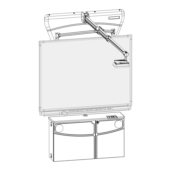
Boom SMART Board Console Floor Side View of the Fully Installed LightRaise Projector Mount Boom Features The hinged aluminum boom is lightweight yet strong. It supports and aims your projector at the wall-mounted SMART Board interactive whiteboard. The projector cables remain out of sight, running inside the boom and behind the wall-bracket covers and the interactive whiteboard until they reach the console. -
Page 12: Console Features
Console Features Fastened directly to the wall, the LightRaise console provides secure and compact accommodation for your peripheral devices in a discrete location below the SMART Board interactive whiteboard. Door Lock Control Panel Speakers External Computer Cable Management Cleats Console with Doors Closed The console is 48"... -
Page 13: Control Panel Features
SMART Board User's Guide. For information on care and cleaning of your projector, see your projector's user manual. If you must service your projector, lower the LightRaise boom and remove the projector. See page 56 for information on servicing. IMPORTANT: Don't service the projector while it's attached to the boom. You may damage the LightRaise mount. -
Page 14: Smart Lightraise Projector Mount Parts
Unpacking the SMART LightRaise Projector Mount The SMART LightRaise projector mount is shipped in two cartons, unless you have purchased only one part of the LightRaise projector mount. Open your carton(s) and verify the contents using these lists: Console Carton Contents •... -
Page 15: Console Hardware Kits
Console Hardware Kits To perform the installation, you'll need to use more than one hardware kit. The kit you use depends on the type of wall onto which you're installing the SMART LightRaise projector mount. Use the following chart to determine which kit(s) you need and to verify the kit contents. -
Page 16: Boom Hardware Kits
Boom Hardware Kits To perform the boom installation, you'll need to use more than one hardware kit. The kit you use depends on the type of wall onto which you're installing the SMART LightRaise projector mount. Use the following chart to determine which kit(s) you need and to verify the kit contents. -
Page 17: Fasteners
Fasteners Different types of fasteners are used in the installation of the SMART LightRaise projector mount. Refer to the following chart to match the screw with its name. NOTE: The illustrations are representative and aren't to scale. Fastener Name Usage #10-32 x "... -
Page 18: Locating The Serial And Identification Numbers
Locating the Serial and Identification Numbers The SMART LightRaise projector mount has two serial numbers: one on the console and one on the projector mounting plate. The console serial number is located inside the console above the power bar. Power Bar Console Serial Number The boom serial number is located on the projector mounting plate. -
Page 19: Installation Overview
Installation should take two people approximately two to three hours. Room Specifications We recommend that you install the LightRaise projector mount in a room at least 6' x 10' (1.8 m x 3.0 m) with a ceiling of 96"(244 cm). Although the product can be installed in a room with a minimum ceiling height of 95"... -
Page 20: Wall Specifications And Mounting Information
Ideally, the wall on which you mount the LightRaise projector mount should be structural or a demising wall. We recommend you install the projector mount on a wall made of cinder block, concrete or a supported wall framed with either wood or metal studs. -
Page 21: Removing An Existing Smart Board Interactive Whiteboard
Tray—this may cause the Pen Tray bracket to bend. Unscrew the mounting bracket from the wall and discard. Order of Installation To install your SMART LightRaise projector mount, you must perform six steps in the order specified. Mark the wall and mount the wall brackets. -
Page 22: Mounting The Wall Brackets
Lower Notch Holes for Bracket Keyholes Top Edge Centerline Hole Line for SMART Board 560 Top Notch Line for SMART Board 580 Centerline Notch Flat (Bottom) Edge Template Tool SMART LightRaise Installation and User's Guide... - Page 23 (see page 37). To mark the wall for the console bracket Decide where you want to mount the LightRaise projector mount and your SMART Board interactive whiteboard. Draw a vertical line down the center of this location. Use the level to ensure this line is straight and plumb.
- Page 24 Drill three holes along the top rows of slots and three along the bottom rows. These holes should be evenly spaced along the width of the bracket. Insert a screw into each hole (for a total of six screws in the slots), being careful not to overtighten each. SMART LightRaise Installation and User's Guide...
- Page 25 Toggle Bolt Anchor Locations Keyholes Console Bracket Remove the console bracket. Drill a ¼" (6 mm) pilot hole and then the final ½" (13 mm) hole through the drywall at each toggle bolt anchor location. SMART LightRaise Installation and User's Guide...
- Page 26 NOTE: Pushing the bolt into the ¼-20 UNC x 1½" anchor too hard Phillips Bolts may cause the plastic to break and the metal end to fall behind the wall. Console Bracket SMART LightRaise Installation and User's Guide...
- Page 27 Hang the console bracket on these two screws, pushing the keyholes firmly down over the protruding screws. Use the bubble level to confirm that the console bracket is level. This is important because the mounting locations for the boom brackets are established from the console bracket. SMART LightRaise Installation and User's Guide...
- Page 28 The metal end straightens against the inside of the drywall to create an anchor. Metal End Plastic Handle SMART LightRaise Installation and User's Guide...
-
Page 29: Marking The Wall And Mounting The Remaining Brackets
#8 x 2½" Phillips round head wood screws and washers wood stud walls) • walls with metal studs: drywall anchors, #8 x 1¼" truss head screws, toggle bolt anchors and ¼-20 UNC x 1½" Phillips pan head bolts • stud finder SMART LightRaise Installation and User's Guide... - Page 30 For SMART Board 560, use the upper edge of the bottom notch For SMART Board 580, use the lower edge of the bottom notch Template tool rests against the leveled console bracket Console Bracket SMART LightRaise Installation and User's Guide...
- Page 31 Centerline Centerline Hole Notch Centerline Illustration not to scale Console Bracket Repeat steps 5 through 7 for the second and third set of marks on the wall. SMART LightRaise Installation and User's Guide...
- Page 32 Insert a screw into each hole, being careful not to overtighten each. Upper Boom Bracket Keyhole Locations Lower Boom Bracket Hanger Bracket Tabs for Hanger Bracket Illustration not to scale Keyhole Locations Spacer Bracket Screws SMART LightRaise Installation and User's Guide...
- Page 33 Hang the spacer bracket on the lowest set of screws, pushing the keyholes firmly down brackets. over the protruding screws. Mark the two screw locations. Upper Boom Bracket Lower Boom Bracket Hanger Bracket Mark hole locations for hanger bracket Illustration not to scale Spacer Bracket Screw Locations SMART LightRaise Installation and User's Guide...
- Page 34 13 Tighten all screws, including those at the keyhole locations. Upper Boom Bracket Keyhole Locations Lower Boom Bracket Hanger Bracket Illustration not to scale Studs Keyhole Locations Spacer Bracket SMART LightRaise Installation and User's Guide...
-
Page 35: Installing The Boom
To attach the LightRaise boom: Carefully lift the boom shaft above the pivot base and guide it into the slots in the pivot base. Slot for Boom Shaft Boom Shaft Pivot Base SMART LightRaise Installation and User's Guide... - Page 36 Lower Boom Bracket Strut End For each strut, insert two #10-32 x " Phillips screws to attach the strut end to the lower boom bracket. #10-32 / " Phillips Screws Strut End Lower Boom Bracket SMART LightRaise Installation and User's Guide...
-
Page 37: Finishing The Boom Installation
Peel the back from the label to reveal the adhesive. Affix the adhesive side of the label following the contour of the lower boom bracket. Strut Bracket Lower Boom Bracket Cover concealment Affix cover label in place concealment label over lower boom bracket SMART LightRaise Installation and User's Guide... - Page 38 • concrete or cinderblock walls: concrete screws To extend the boom and secure it: Slide the telescoping beam out of the main beam. Main Beam Telescoping Beam Strut Slide Struts Main Beam End Plate SMART LightRaise Installation and User's Guide...
- Page 39 SMART Board interactive whiteboard. This information is found on the SMART LightRaise Projector Mount Supported Projector Reference List that came with your LightRaise projector mount or at www.smarttech.com/lightraise. Underside of Boom...
- Page 40 Top Cover NOTE: You may have to cut the end of the telescoping beam cover. Measure the cable trough and use the plastic cutting tool. Be careful to cut the cover at the correct length. SMART LightRaise Installation and User's Guide...
- Page 41 The thumbscrews will engage into the holes when the holes align with the screws. Tighten the captive thumbscrews by hand. Telescoping Beam Spring Cover Strut Slide Captive Thumbscrews SMART LightRaise Installation and User's Guide...
- Page 42 SMART Board interactive whiteboard. Ensure the loops are flat enough that they won't interfere with the interactive whiteboard. Use the provided tie wraps to hold the loops to the hanger bracket. Tie Wraps SMART LightRaise Installation and User's Guide...
- Page 43 Tilt the upper boom cover and maneuver it between the struts and the boom. Upper Boom Cover Upper Boom Cover Groove on Groove on Lower Boom Lower Boom Lower Boom Cover Lower Boom Cover Cover Cover SMART LightRaise Installation and User's Guide...
- Page 44 Follow steps 3 and 4 to return the upper cover to its place. Insert a #8 x 1¼" truss head screw into each drywall anchor and use the Phillips hand screwdriver to tighten each screw. Truss Head Screws SMART LightRaise Installation and User's Guide...
-
Page 45: Installing The Console
Hanging Rail Security Fastener Locations NOTE: Cables not shown. Open the console's front doors and locate the slots for the security fasteners. Align these holes with the fastener locations on the console bracket. SMART LightRaise Installation and User's Guide... -
Page 46: Installing The Cable Cleats
Insert each cable cleat bolt through a hole on the right side of the console. Using the " wrench, attach a " nut and washer onto each cable cleat bolt protruding inside the console. Cleat Hole Nuts Cable Cleats Cleat Hole SMART LightRaise Installation and User's Guide... -
Page 47: Connecting The Cables
4. Connecting the Cables Where possible, all connections for the SMART LightRaise projector mount have been done for you. However, during installation, you must make various connections to link the components. The following five bundles of cables are located inside the console: •... - Page 48 Connect the power plug (P05) to the projector power (P02) cable extension included in the cable bundle on the left side. NOTE: See the illustration on the next page. SMART LightRaise Installation and User's Guide...
- Page 49 Alternatively, use the USB cables (C06 and C07) to your computer's USB port. SMART LightRaise Installation and User's Guide...
- Page 50 S-video cable. Obtain the country-specific power adapter from the power kit. Connect this adapter to the power (P04) cable extension. Connect the country power adapter to the VCR or DVD player's power plug. SMART LightRaise Installation and User's Guide...
- Page 51 NOTE: To release the cable bundle from the cable cleats, put your thumb on one cleat's center post while you gently pull its handle out and turn it. The handle turns so you can easily free the cable bundle. See page 54 for details on connecting your external computer. SMART LightRaise Installation and User's Guide...
-
Page 52: Installing The Smart Board Interactive Whiteboard And Projector
NOTE: Bracket covers not shown Lower the board until the bracket on the back of the board rests firmly on the hanger bracket. Test that the board is secure by sliding it slightly sideways before releasing your hold. SMART LightRaise Installation and User's Guide... - Page 53 Follow the instructions included with the projector mount kit to attach the projector to the projector mount. Follow the instructions included with the projector mount kit to connect the cables to the projector bundle. SMART LightRaise Installation and User's Guide...
-
Page 54: Finalizing The Installation
After choosing the cable grommet situated nearest your network wall socket, locate the console, you'll network cable, feed it through that grommet, and plug it into the wall connection. need to supply a network patch Press the System On button on the control panel. cable. SMART LightRaise Installation and User's Guide... -
Page 55: Adjusting The Computer
We recommend that you set your monitor to shut off after 30 minutes of computer inactivity. Your LightRaise projector mount then goes into a Wait state. After another 30 minutes, the projector is shut off by the console's firmware, if a computer is the selected source. - Page 56 To set the resolution on a Macintosh computer: Click the Monitors button on the Control Panel strip and select Open Monitors Control Panel. Open the Apple menu, select Control Panels and then select Monitors. The Monitors window for your computer opens. SMART LightRaise Installation and User's Guide...
- Page 57 Open the Apple menu, select Control Panels and select Energy Saver. The Energy Saver dialog box opens to the Sleep Setup tab. Drag the sliding bar to 30 minutes. Close the dialog box by clicking the top-left corner. SMART LightRaise Installation and User's Guide...
-
Page 58: Operating The Smart Lightraise Projector Mount
The LightRaise mount is powering slowly down. (approximately once per second) NOTE: If any source indicator flashes continually, contact SMART Technical Support. See page 58 for contact information. SMART LightRaise Installation and User's Guide... -
Page 59: Using The Smart Lightraise Projector Mount
Using the SMART LightRaise Projector Mount The SMART LightRaise projector mount is easy to use. One button press starts the system and one press shuts it down. System Off Indicator Lit Control Panel in Full Stop State To start the LightRaise projector mount: If required, power on the computer, VCR or DVD player and your external computer. -
Page 60: Automatic Shut-Off Feature
At first, the System Off indicator will flash rapidly. After approximately five minutes, it will flash more slowly while the fan cools off the projector lamp. Finally, the LightRaise mount shuts the projector down and the red System Off indicator glows steadily. -
Page 61: Changing The Volume Level
Consult the SMART Board User's Guide or the online Help files for detailed information on your SMART Board interactive whiteboard. While every effort has been made for the SMART LightRaise projector mount to absorb normal building vibration, you may find that the LightRaise mount does shift slightly with normal use. -
Page 62: Using An External Computer
COM port and one to the monitor port. You have already connected these cables to the LightRaise mount and have placed them conveniently on the right side of the console, wrapped around the cable cleats (see page 43). -
Page 63: Activating Your Video Port
Settings tab to access this information. Click the CRT/Panel option to activate simultaneous monitor and external video port display. This allows your image to appear on both your monitor and the SMART Board interactive whiteboard. SMART LightRaise Installation and User's Guide... -
Page 64: Servicing The Smart Lightraise Projector Mount
However, your projector may need occasional servicing. Follow the guidelines in your projector's owner manual for servicing and bulb replacement. Don't service the projector while it is powered on. You should unplug the LightRaise console before performing any servicing. IMPORTANT: Don't service the projector when it is attached to the boom. -
Page 65: Upgrading Your Firmware
Upgrading Your Firmware The firmware in the control panel has flashable memory. Should your firmware require an upgrade, you will be contacted by SMART Technologies Inc. and instructions will be provided. SMART LightRaise Installation and User's Guide... -
Page 66: Customer Support
• the version of your operating system • the serial numbers of your product (see page 10 to locate the LightRaise projector mount serial number) • the name of the application software causing the problem, if applicable Other SMART Contacts Main Switchboard: toll-free at 1.888.42.SMART or outside North America +1.403.245.0333... -
Page 67: Product Warranty
Product Warranty The SMART LightRaise projector mount is covered by a one-year limited equipment warranty. If you need to return defective merchandise, call SMART Technical Support to receive the appropriate Return of Merchandise Authorization, as well as shipping instructions so that product can be sent to an authorized service center. -
Page 68: Appendix A: Console Functional Diagram
Appendix A: Console Functional Diagram SMART LightRaise Installation and User's Guide... -
Page 69: Appendix B: Console Running Wire List
Appendix B: Console Running Wire List SMART LightRaise Installation and User's Guide... - Page 70 Depending on the projector used, the gender on the connector and the type of connectors used may change. If the VCR/DVD player doesn't have an S-video output, use an RCA/S-video adapter to output video to the projector. SMART LightRaise Installation and User's Guide...
-
Page 71: Index
Identification Numbers, 10 Features, 4 Indicators Control Panel, 50 Hardware Kits, 7 Input Source Changing, 53 Installing, 37–38 Installation Contacting SMART Technical Support, 58 Cable Cleats, 38 Control Panel Computer, 41 Features, 5 Connections, 39–43 SMART LightRaise Installation and User's Guide... - Page 72 Warnings, i Warranty Shipping Charges, 59 Registration Card, 59 Windows Operating System Resolution Energy-Saving Settings, 48 Changing for Windows Operating Resolution, 47 System, 47 Wire Listing, 61 Changing on Macintosh Computer, 48 Restarting, 52 SMART LightRaise Installation and User's Guide...
- Page 73 Suite 600, 1177 – 11th Avenue SW, Calgary, AB CANADA T2R 1K9 Support: 1.866.518.6791 or outside North America +1.403.228.5940 Main Switchboard: 1.888.42.SMART or outside North America +1.403.245.0333 Fax (24 hours): 403.245.0366 support@smarttech.com www.smarttech.com Printed in Canada 99-306-00 REV A0...
Need help?
Do you have a question about the LightRaise and is the answer not in the manual?
Questions and answers